Table of Contents
Advertisement
Quick Links
Advertisement
Table of Contents

Related Manuals for Supermicro X9SRW-F


Summary of Contents for Supermicro X9SRW-F
- Page 1 X9SRW-F USER’S MANUAL Revision 1.0b...
- Page 2 This product, including software and docu- mentation, is the property of Supermicro and/or its licensors, and is supplied only under a license. Any use or reproduction of this product is not allowed, except as expressly permitted by the terms of said license.
-
Page 3: About This Motherboard
1Gb LAN, eight (8) USB ports, and an IPMI port make the X9SRW series ideal for high end rack-mounted single-processor platforms. Please refer to our website (http://www.supermicro.com/products/) for processor and memory support updates. *This product is intended to be installed and serviced by professional technicians. -
Page 4: Conventions Used In The Manual
X9SRW Motherboard Series User’s Manual Conventions Used in the Manual: Special attention should be given to the following symbols for proper installation and to prevent damage done to the components or injury to yourself: Danger/Caution: Instructions to be strictly followed to prevent catastrophic system failure or to avoid bodily injury Warning: Critical information to prevent damage to the components or data loss. -
Page 5: Contacting Supermicro
Super Micro Computer, Inc. 980 Rock Ave. San Jose, CA 95131 U.S.A. Tel: +1 (408) 503-8000 Fax: +1 (408) 503-8008 Email: marketing@supermicro.com (General Information) support@supermicro.com (Technical Support) Web Site: www.supermicro.com Europe Address: Super Micro Computer B.V. Het Sterrenbeeld 28, 5215 ML... -
Page 6: Table Of Contents
X9SRW Motherboard Series User’s Manual Table of Contents Preface About This Motherboard ....................iii Manual Organization ..................... iii Conventions Used in the Manual: .................iv Contacting Supermicro ....................v Chapter 1 Introduction Overview ......................1-1 Checklist ......................1-1 Motherboard Features ..................1-7 Chipset Overview .................. - Page 7 Table of Contents Removing Memory Modules ................2-9 Memory Support .................... 2-10 Memory Population Guidelines ..............2-11 Motherboard Installation ................2-12 Tools Needed ....................2-12 Location of Mounting Holes ................2-12 Installing the Motherboard ................2-13 Connectors/IO Ports ..................2-14 Motherboard I/O Backpanel ................2-14 Universal Serial Bus (USB) ..............
- Page 8 X9SRW Motherboard Series User’s Manual Watch Dog Reset (JWD) ................2-29 BMC Enable/Disable (JPB1) ..............2-29 Onboard VGA Enable (JPG1) ..............2-30 Unit Identifier Switch (UID) ............... 2-30 BIOS Recovery (JP3) ................2-31 ME Recovery (JPME1) ................2-31 VRM SMB Clock/Data (J29/J30) .............. 2-31 Onboard Indicators ..................
- Page 9 Table of Contents System Overview: The following BIOS information will be displayed: ..4-3 System Time/System Date ................ 4-3 Supermicro X9SRW-F ................4-3 Memory Information ................... 4-3 Total Memory ....................4-3 4-3 Advanced Setup Configurations..............4-4 Quiet Boot ....................4-4 AddOn ROM Display Mode ................ 4-4 Bootup Num-Lock ..................
- Page 10 X9SRW Motherboard Series User’s Manual SATA Mode ....................4-11 IDE Mode ....................4-11 Serial-ATA Controller 0~1 ................4-11 AHCI Mode ....................4-12 Aggressive Link Power Management ............4-12 Port 0~5 Hot Plug..................4-12 Staggered Spin Up ................... 4-12 RAID Mode ....................4-12 Port 0~5 Hot Plug..................4-12 ...
- Page 11 Table of Contents Runtime Error Logging Support ............... 4-19 Memory Correction Error Threshold ............4-19 PCI Error Logging Support ............... 4-19 Erase Event Log ..................4-20 When Log is Full ..................4-20 Log System Boot Event ................4-20 MECI ......................4-20 METW .......................
- Page 12 X9SRW Motherboard Series User’s Manual Appendix A BIOS Error Beep Codes BIOS Error Beep Codes .................A-1 Appendix B Software Installation Instructions Installing Drivers ....................B-1 B-2 Configuring SuperDoctor ® III ................B-2 Appendix C UEFI BIOS Recovery Instructions An Overview to the UEFI BIOS ..................C-1 How to Recover the UEFI BIOS Image (-the Main BIOS Block) .......C-1 To Recover the Main BIOS Block Using a USB-Attached Device ......C-1...
-
Page 13: Introduction
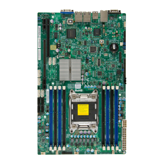
Checklist Congratulations on purchasing your computer motherboard from an acknowledged leader in the industry. Supermicro boards are designed with the utmost attention to detail to provide you with the highest standards in quality and performance. Please check that the following items have all been included with your motherboard. - Page 14 X9SRW Motherboard Series User’s Manual Motherboard Image Note: All graphics shown in this manual were based upon the latest PCB Revision available at the time of publishing of the manual. The motherboard you've received may or may not look exactly the same as the graphics shown in this manual.
- Page 15 Chapter 1: Introduction Motherboard Layout JUIDB1 COM1 JI2C2/JI2C3 1-2:Enable JCOM1 JVGA1 2-3:Disable JPL1:LAN1 JPG1: VGA 1-2:ENABLE 1-2:Enable 2-3:DISABLE 2-3:Disable JPL2:LAN2 1-2:ENABLE 2-3:DISABLE LED2 JWD: 1-2:RST 2-3:NIMI JPMB JIPMB1 JLAN2 JLAN1 LAN2 LAN1 SXB1A JWP1: WRITE PROTECT JOH1 JOH1:OVER HEAT LED SXB1A: LEFT_WIO_UP SXB1B: LEFT_WIO_MIDDLE SXB2: RIGHT_WIO...
-
Page 16: Motherboard Quick Reference
X9SRW Motherboard Series User’s Manual Motherboard Quick Reference JVGA1 JLAN1 USB0/1 JCOM1 JLAN2 USB2/3 JI2C3 JUIDB1 COM1 JI2C2/JI2C3 1-2:Enable JCOM1 JVGA1 2-3:Disable JPL1:LAN1 JI2C2 JPG1: VGA 1-2:ENABLE 1-2:Enable 2-3:DISABLE 2-3:Disable JPL2:LAN2 1-2:ENABLE 2-3:DISABLE LED2 IPMI JWD: 1-2:RST 2-3:NIMI JIPMB1 JPMB JIPMB1 LED2 JLAN2... - Page 17 Chapter 1: Introduction Motherboard Headers/Connectors Connector Description I-SAS0~I-SAS3 (SATA 3.0) I-SATA 3.0 ports (supports up to 6Gb/s) I-SATA0, I-SATA1 (SATA 3.0) Internal SATA ports (I-SATA0 and I-SATA1 supports up to I-SATA2~I-SATA5 (SATA 2.0) 6Gb/s), I-SATA2~I-SATA5 supports upo to 3Gb/s) FAN1~FAN5 Headers for system cooling fans JSD1 SATA DOM (Disk On Module) Power Connector...
- Page 18 X9SRW Motherboard Series User’s Manual Motherboard Jumpers Jumper Description Default JI2C2/JI2C3 SMB to PCI Slots On (Enabled) JPG1 Onboard VGA Enable Pins 1-2 (On) JPL1 LAN1 Enable Pins 1-2 (Enabled) JPME1 Intel ME Mode Select Pins 1-2 (Normal) Unit ID Switch Off (Disabled) Watch Dog Timer Reset Pins 1-2 (Reset)
-
Page 19: Motherboard Features
Expansion PCI Slots (using riser cards) Two (2) PCI-Express 3.0 x16 Slot, using Supemicro riser card P/N RSC-R1UW-2E16 One (1) PCI-Express 2.0 x8 Slot, using Supermicro riser card P/N RSC-R1UW-E8R Network Connections Integrated LAN One (1) Intel i350 Dual Gb LAN... - Page 20 X9SRW Motherboard Series User’s Manual PC Health Monitoring CPU & Chassis Monitoring Onboard voltage monitors for CPU core, +1.8V, +3.3V, +5V, +/-12V, +3.3V Stdby, +5V Stdby, VBAT, Memory, Chipset CPU 5-phase switching voltage regulator CPU/System overheat LED and control CPU Thermal Trip support CPU &...
-
Page 21: Motherboard Block Diagram
Chapter 1: Introduction Motherboard Block Diagram X9SRW-F VR12 #D-2 5 PHASE #D-1 130W #C-2 #C-1 #B-2 Sandybridge-EP #B-1 8 SNB CORE #A-2 DDR-III #A-1 DMI2 SXB1 PCI-E X16 G3 PCI-E X16 G3 SXB2 PCI-E X8 G3 (PE1) DMI2 4GB/s PORTs#0~3... -
Page 22: Chipset Overview
X9SRW Motherboard Series User’s Manual Chipset Overview The Intel® C600 series is a single chip solution that is designed for dedicated servers and work- stations. It supports high-speed SAS, SATA and advanced requirements for Intel Xeon platforms. Intel C600 Chipset Features •... -
Page 23: Special Features
Chapter 1: Introduction Special Features Recovery from AC Power Loss Basic I/O System (BIOS) provides a setting for you to determine how the system will respond when AC power is lost and then restored to the system. You can choose for the system to remain powered off (in which case you must press the power switch to turn it back on), or for it to automatically return to a power-on state. -
Page 24: Acpi Features
X9SRW Motherboard Series User’s Manual certain system events. For example, you can also configure Supero Doctor to provide you with warnings when the system temperature, CPU temperatures, voltages and fan speeds go beyond predefined thresholds. ACPI Features ACPI stands for Advanced Configuration and Power Interface. The ACPI specifica- tion defines a flexible and abstract hardware interface that provides a standard way to integrate power management features throughout a PC system, including its hardware, operating system and application software. -
Page 25: Super I/O
Chapter 1: Introduction 2. To provide adequate power to SATA devices, please connect the SATA DOM PWR connector (JWF1) to the power supply. It is strongly recommended that you use a high quality power supply that meets ATX power supply Specification 2.02 or above. It must also be SSI compliant. (For more information, please refer to the web site at http://www.ssiforum.org/). -
Page 26: Installation
Chapter 2: Installation Chapter 2 Installation Static-Sensitive Devices Electrostatic-Discharge (ESD) can damage electronic com ponents. To avoid damaging your system board, it is important to handle it very carefully. The following measures are generally sufficient to protect your equipment from ESD. Precautions •... -
Page 27: Processor And Heatsink Installation
The LGA2011 Socket Currently, there are two kinds of LGA2011 socket mounted on Supermicro moth- erboards, a 'regular' and a 'narrow' sized socket. Though they may look slightly different from one another, the labeling, operation of the hardware, mounting of the CPU are similar on both types. -
Page 28: Opening The Lga2011 Socket
Chapter 2: Installation Opening the LGA2011 Socket The instructions on the following pages will show the 'regular' type socket. How- ever, they also apply to the 'narrow' type as well. The drawings are provided for illustration purposes only. 1. Before opening the LGA2011 socket, remove the black 'IMPORTANT!' plas- tic protective cap using your fingers and save it for future use. - Page 29 X9SRW Motherboard Series User’s Manual 3. Press the second load lever labeled 'Close 1st' to release the load plate which covers the CPU socket from its locking position. Press down on Load Lever 'Close 1st' Pull lever away from the socket Note: In some sockets, "Close 1st"...
-
Page 30: Installing The Lga2011 Processor
Chapter 2: Installation Installing the LGA2011 Processor 1. Use your thumb and index finger to hold the CPU on its edges. Align the CPU keys (semi-circle cutouts) against the socket keys. Socket Keys CPU Keys 2. Once it is aligned, carefully lower the CPU straight down into the socket. (Do not drop the CPU on the socket. - Page 31 X9SRW Motherboard Series User’s Manual 3. Once it is aligned, carefully lower the CPU straight down into the socket. (Do not drop the CPU on the socket. Do not move the CPU horizontally or verti- cally. 4. Do not rub the CPU against the surface or against any pins of the socket to avoid damaging the CPU or the socket.) 5.
-
Page 32: Installing A Passive Cpu Heatsink
Chapter 2: Installation Installing a Passive CPU Heatsink 1. Do not apply any thermal grease to the heatsink or the CPU die -- the re- quired amount has already been applied. 2. Place the heatsink on top of the CPU so that the four mounting holes are aligned with those on the Motherboard's and the Heatsink Bracket under- neath. -
Page 33: Removing The Heatsink
X9SRW Motherboard Series User’s Manual Removing the Heatsink Warning: We do not recommend that the CPU or the heatsink be removed. However, if you do need to uninstall the heatsink, please follow the instruc- tions below to uninstall the heatsink to prevent damage done to the CPU or the CPU socket. -
Page 34: Installing Ddr3 Memory
Chapter 2: Installation Installing DDR3 Memory Note: Check the Supermicro website for recommended memory mod- ules. CAUTION Exercise extreme care when installing or removing DIMM modules to prevent any possible damage. JUIDB1 COM1 JI2C2/JI2C3 1-2:Enable JVGA1 JCOM1 2-3:Disable JPG1: VGA... -
Page 35: Memory Support
X9SRW Motherboard Series User’s Manual Memory Support The X9SRW Motherboard supports up to 256GB of 1600/1333/1066/800 MHz ECC/Non-ECC DDR3 DIMMs in eight (8) memory slots (UDIMM/RDIMM). Popu- lating these DIMM modules with a pair of memory modules of the same type and same size will result in interleaved memory, which will improve memory perfor- mance. -
Page 36: Memory Population Guidelines
Chapter 2: Installation Memory Population Guidelines When installing memory modules, the DIMM slots should be populated in the follow- ing order: DIMMA1, DIMMB1, DIMMC1, DIMMD1 then DIMMA2, DIMMB2, DIMMC2, DIMMD2. Populate the blue-colored slots first. • Always use DDR3 DIMM modules of the same size, type and speed. •... -
Page 37: Motherboard Installation
X9SRW Motherboard Series User’s Manual Motherboard Installation All motherboards have standard mounting holes to fit different types of chassis. Make sure that the locations of all the mounting holes for both motherboard and chassis match. Although a chassis may have both plastic and metal mounting fas- teners, metal ones are highly recommended because they ground the motherboard to the chassis. -
Page 38: Installing The Motherboard
Chapter 2: Installation Installing the Motherboard 1. Install the I/O shield into the chassis. 2. Locate the mounting holes on the motherboard. 3. Locate the matching mounting holes on the chassis. Align the mounting holes on the motherboard against the mounting holes on the chassis. Pan head screws (8 pieces) 4. -
Page 39: Connectors/Io Ports
X9SRW Motherboard Series User’s Manual Connectors/IO Ports The I/O ports are color coded in conformance with the PC 99 specification. See the figure below for the colors and locations of the various I/O ports. Motherboard I/O Backpanel T-SGPIO3 T-SGPIO2 T-SGPIO4 JPL1 T-SGPIO1 JI2C1... -
Page 40: Universal Serial Bus (Usb)
Chapter 2: Installation Universal Serial Bus (USB) There are four (4) Universal Serial Bus (USB) 2.0 ports located on the I/O back panel, which may be used to plug in a USB keyboard and/or mouse. There are also four (4) USB 2.0 ports on two headers that can be used to provide front chas- sis access using separate USB cables (not included). -
Page 41: Ethernet Ports
X9SRW Motherboard Series User’s Manual Ethernet Ports LAN Ports Pin Definition Two Ethernet ports (LAN1/LAN2) are Pin# Definition located next to the VGA port on the TD0- SGND I/O Backpanel. In addition, an IPMI TD0+ P3V3SB Dedicated LAN is also located above TD1- Act LED USB 0/1 ports to provide a dedicated... -
Page 42: Front Control Panel
These connectors are designed specifically for use with a Supermicro server chassis. See the figure below for the descriptions of the various control panel buttons and LED indicators. Refer to the following section for descriptions and pin definitions. -
Page 43: Front Control Panel Pin Definitions
X9SRW Motherboard Series User’s Manual Front Control Panel Pin Definitions NMI Button NMI Button Pin Definitions (JF1) The non-maskable interrupt (NMI) but- Pin# Definition ton header is located on pins 19 and Control 20 of JF1. Refer to the table on the Ground right for pin definitions. -
Page 44: Nic1/Nic2 (Lan1/Lan2)
Chapter 2: Installation NIC1/NIC2 (LAN1/LAN2) LAN1/LAN2 LED Pin Definitions (JF1) The NIC (Network Interface Controller) Pin# Definition LED connection for LAN port 1 is located 9/11 on pins 11 and 12 of JF1, and the LED 10/12 Ground connection for LAN Port 2 is on Pins 9 and 10. -
Page 45: Reset Button
X9SRW Motherboard Series User’s Manual Reset Button Reset Button Pin Definitions (JF1) The Reset Button connection is located Pin# Definition on pins 3 and 4 of JF1. Attach this to a Reset hardware reset switch on the computer Ground case to reset the system. Refer to the table on the right for pin definitions. -
Page 46: Connecting Cables & Optional Devices
Chapter 2: Installation Connecting Cables & Optional Devices This section provides brief descriptions and pin-out definitions for onboard headers and connectors. Be sure to use the correct cable for each header or connector. ATX Power 24-pin Connector ATX Main PWR (JPW1) & CPU PWR Pin Definitions (JPW1) Connectors (JPW2) Pin#... -
Page 47: Fan Headers (Fan1~6)
X9SRW Motherboard Series User’s Manual Fan Headers (FAN1~6) Fan Header Pin Definitions The X9SRW series has five fan headers (Fan Pin# Definition 1~Fan 5). These fans are 4-pin fan headers. Ground (Black) Pins 1-3 of the fan headers are backward com- +12V (Red) patible with the traditional 3-pin fans, but will Tachometer... -
Page 48: Speaker (Jd1)
Chapter 2: Installation Speaker (JD1) Speaker Connector Pin Definitions On the JD1 header, Pins 3~4 are used for Pin Setting Definition the internal speaker. Close Pins 3~4 with a Pins 3~4 Internal Speaker jumper or cap to use the onboard speaker. Pins1~4 External Speaker If you wish to use an external speaker, at-... -
Page 49: Power Supply I C (Jpi2C)
X9SRW Motherboard Series User’s Manual Power Supply I C (JPI2C) PWR Supply I Pin Definitions The Power Supply I2C Connector, Pin# Definition located at JPI2C, monitors the status Clock of the power supply, fan and system Data temperature. See the table on the right PWR Fail for pin definitions. -
Page 50: T-Sgpio 1/2 & 3-Sgpio 1/2 Headers
Chapter 2: Installation T-SGPIO 1/2 & 3-SGPIO 1/2 Headers Serial_Link-SGPIO Pin Definitions Two T-SGPIO (Serial-Link General Pur- Pin# Definition Definition pose Input/Output) headers are located next to the I-SATA Ports on the mother- Ground DATA Out board. Additionally, two 3-SGPIO ports Load Ground (for SAS) are also located next to USB... -
Page 51: Overheat/Fan Fail Led (Joh1 )
X9SRW Motherboard Series User’s Manual Overheat/Fan Fail LED (JOH1 Overheat LED Pin Definitions The JOH1 header is used to connect an Pin# Definition LED to provide warnings of chassis over- 5vDC heat. This LED will also blink to indicate a OH Active fan failure. -
Page 52: Jumper Settings
Chapter 2: Installation Jumper Settings Explanation of Jumpers To modify the operation of the mother- board, jumpers can be used to choose between optional settings. Jumpers create shorts between two pins to change the function of the connector. Pin 1 is identified with a square solder pad on the printed circuit board. -
Page 53: Clear Cmos (Jbt1)
X9SRW Motherboard Series User’s Manual Clear CMOS (JBT1) JBT1 is used to clear CMOS. Instead of pins, this "jumper" consists of contact pads to prevent accidental clearing of CMOS. To clear CMOS, use a metal object such as a small screwdriver to touch both pads at the same time to short the connection. Always remove the AC power cord from the system before clearing CMOS. -
Page 54: Watch Dog Reset (Jwd)
Chapter 2: Installation Watch Dog Reset (JWD) Watch Dog Jumper Settings Watch Dog (JWD) is a system monitor that Jumper Setting Definition can reboot the system when a software Pins 1-2 Reset (default) application hangs. Close Pins 1-2 to reset Pins 2-3 the system if an application hangs. -
Page 55: Onboard Vga Enable (Jpg1)
X9SRW Motherboard Series User’s Manual Onboard VGA Enable (JPG1) JPG1 allows you to enable or disable the onboard VGA connector. The default posi- tion is on pins 1 and 2 to enable VGA. See VGA Enable/Disable Jumper Settings the table on the right for jumper settings. Jumper Setting Definition Pins 1-2... -
Page 56: Bios Recovery (Jp3)
Chapter 2: Installation BIOS Recovery (JP3) BIOS Recovery Pin Definitions The BIOS Recovery (JP3) is used to en- Pin# Definition able or disable the BIOS Recovery feature Open (Default) of the motherboard. Install the jumper on Ground pins 2-3 to begin the recovery process. Recover ME Recovery (JPME1) ME Recovery... -
Page 57: Onboard Indicators
X9SRW Motherboard Series User’s Manual Onboard Indicators LAN Port LEDs The LAN ports are located on the I/O Link LEDs (Green/Amber/Off) backpanel of the motherboard. Each Eth- LED Color Definition ernet LAN port has two LEDs. The yellow No Connection or 10 Mbps Green 100 Mbps LED indicates activity, while the Link LED... -
Page 58: Rear Unit Id Led (Le2)
Chapter 2: Installation Rear Unit ID LED (LE2) Rear UID LED LED Settings The rear Unit ID LED is located at LE2 on Blue: Solid UID Toggled On the back panel. This LED is used in con- UID Toggled Off junction with the rear UID switch to provide easy identification of a system that might be in need of service. -
Page 59: Sata Connections
X9SRW Motherboard Series User’s Manual SATA Connections SATA/SAS Connectors SATA/SAS Connections Pin Definitions Six Serial ATA (SATA) connectors (I-SATA Pin# Signal 0~5) are located on the motherboard. Of Ground these, I-SATA0 and I-SATA1 are SATA 3.0 SATA_TXP ports. In additon, SAS0~SAS3 are also used SATA_TXN as I-SATA 6Gb/s (SATA 3.0) ports, giving the Ground... -
Page 60: Troubleshooting
Chapter 3: Troubleshooting Chapter 3 Troubleshooting Troubleshooting Procedures Use the following procedures to troubleshoot your system. If you have followed all of the procedures below and still need assistance, refer to the ‘Technical Support Procedures’ and/or ‘Returning Merchandise for Service’ section(s) in this chapter. Always disconnect the AC power cord before adding, changing or installing any hardware components. -
Page 61: No Video
1. Make sure that the DIMM modules are properly installed and fully seated in the slots. 2. You should be using memory recommended by Supermicro (see Section 2-3). Also, it is recommended that you use the memory modules of the same type and speed for all DIMMs in the system. -
Page 62: Technical Support Procedures
Before contacting Technical Support, please make sure that you have followed all the steps listed below. Also, Note that as a motherboard manufacturer, Supermicro does not sell directly to end users, so it is best to first check with your distributor or reseller for troubleshooting services. -
Page 63: Frequently Asked Questions
Answer: It is recommended that you do not upgrade your BIOS if you are not experiencing any problems with your system. Updated BIOS files are located on our website at http://www.supermicro.com/support/bios/. Please check our BIOS warning message and the information on how to update your BIOS on our web site. - Page 64 Chapter 3: Troubleshooting Question: Why do I get an error message “IASTOR.SYS read error” and "press F6 to install Intel RAID driver" when installing Windows on my motherboard? Answer: To solve this issue, disable the IPMI jumper (if your motherboard has this feature).
-
Page 65: Battery Removal And Installation
X9SRW Motherboard Series User’s Manual Battery Removal and Installation Battery Battery Lock Battery Removal To remove the onboard battery, follow the steps below: 1. Power off your system and unplug your power Battery Holder cable. 2. Locate the onboard battery as shown below. 3. -
Page 66: Returning Merchandise For Service
You can obtain service by calling your vendor for a Returned Merchandise Authorization (RMA) number. For faster service, you may also obtain RMA authorizations online (http://www.supermicro. com/support/rma/). When you return the motherboard to the manufacturer, the RMA number should be prominently displayed on the outside of the shipping carton, and mailed prepaid or hand-carried. - Page 67 X9SRW Motherboard Series User’s Manual Notes...
-
Page 68: Introduction
When an option is selected in the left frame, it is highlighted in white. Often a text message will accompany it. (Note: the AMI BIOS has default text messages built in. Supermicro retains the option to include, omit, or change any of these text messages.) The AMI BIOS Setup Utility uses a key-based navigation system called "hot keys". -
Page 69: How To Start The Setup Utility
Warning! Do not upgrade the BIOS unless your system has a BIOS-related issue. Flashing the wrong BIOS can cause irreparable damage to the system. In no event shall Supermicro be liable for direct, indirect, special, incidental, or consequential damages arising from a BIOS update. If you have to update the BIOS, do not shut down or reset the system while the BIOS is updating. -
Page 70: System Overview: The Following Bios Information Will Be Displayed
Day MM/DD/YY format. The time is entered in HH:MM:SS format. (Note: The time is in the 24-hour format. For example, 5:30 P.M. appears as 17:30:00.) Supermicro X9SRW-F Version: This item displays the version of the BIOS used in the system. -
Page 71: Advanced Setup Configurations
X9SRW Motherboard Series User’s Manual Advanced Setup Configurations Use the arrow keys to select Boot Setup and hit <Enter> to access the submenu items: Quiet Boot This option allows the bootup screen options to be modified between POST mes- sages or the OEM logo. Select Disabled to display the POST messages. Select Enabled to display the OEM logo instead of the normal POST messages. -
Page 72: Interrupt 19 Capture
Chapter 4: AMI BIOS Interrupt 19 Capture Interrupt 19 is the software interrupt that handles the boot disk function. When this item is set to Enabled, the ROM BIOS of the host adaptors will "capture" Interrupt 19 at boot and allow the drives that are attached to these host adaptors to function as bootable disks. -
Page 73: Hyper Threading
X9SRW Motherboard Series User’s Manual Hyper Threading Set to Enabled to use the processor's Hyper Threading Technology feature. The options are Enabled and Disabled. Active Processor Cores Set to Enabled to use a processor's Second Core and beyond. (Please refer to Intel's web site for more information.) The options are All, 1, 2, and 4. -
Page 74: Intel® Virtualization Technology (Available When Supported By The Cpu)
Chapter 4: AMI BIOS Intel® Virtualization Technology (Available when supported by the CPU) Select Enabled to use the feature of Virtualization Technology to allow one plat- form to run multiple operating systems and applications in independent partitions, creating multiple "virtual" systems in one physical computer. The options are Enabled and Disabled. -
Page 75: Chipset Configuration
X9SRW Motherboard Series User’s Manual Energy Performance This setting allows the user to adjust the fan speed based on performance (maxi- mum cooling) or energy efficiency (maximum energy savings) The options are Performance, Balanced Performance, Balanced Energy, and Energy Efficient. Long duration power limit - this is the processor power consumption limit (in Watts) during a long duration time window. -
Page 76: Dimm Configuration
Chapter 4: AMI BIOS IOU1-PCIe Port This feature allows the user to set the PCI-Exp bus speed between IOU1 and PCI-e port. The options are x4x4 and x8. SXB2 PCI-E 3.0 x8 Link Speed This feature enables the user to select the target link speed for this slot. The options are GEN1 and GEN2. -
Page 77: South Bridge Configuration
X9SRW Motherboard Series User’s Manual Rank Interleaving This feature selects from the different rank memory interleaving methods. The options are Auto, 1 Way, 2 Way, 4 Way and 8 Way. Patrol Scrub Patrol Scrubbing is a process that allows the CPU to correct correctable memory errors detected on a memory module and send the correction to the requestor (the original source). -
Page 78: Sata Configuration
Chapter 4: AMI BIOS Legacy USB Support This feature enables support for legacy USB devices. Select Auto to disable legacy support if USB devices are not present. Select Disable to have USB devices available only for EFI applications. The options are Enabled, Disabled and Auto. -
Page 79: Ahci Mode
X9SRW Motherboard Series User’s Manual AHCI Mode The following items are displayed when AHCI Mode is selected: Aggressive Link Power Management This feature Enables or Disables Aggressive Link Power Management support for Cougar Point B0 stepping and later. The options are Enabled and Disabled. -
Page 80: Pci Latency Timer
Chapter 4: AMI BIOS PCI Latency Timer This feature sets the latency Timer of each PCI device installed on a PCI bus. Se- lect 64 to set the PCI latency to 64 PCI clock cycles. The options are 32 PCI Bus Clocks, 64 PCI Bus Clocks, 96 PCI Bus Clocks, 128 PCI Bus Clocks, 160 PCI Bus Clocks, 192 PCI Bus Clocks, 224 PCI Bus Clocks and 248 PCI Bus Clocks. -
Page 81: Load Onboard Lan1 Option Rom / Load Onboard Lan2 Option Rom
X9SRW Motherboard Series User’s Manual Load Onboard LAN1 Option ROM / Load Onboard LAN2 Option ROM This feature is to enable or disable the onboard option ROMs. The options are Dis- abled and Enabled. The default for LAN 1 is Enabled. Default for LAN 2 is Disabled. VGA Priority This option allows the user to specify which graphics controller to be used as the primary boot device. -
Page 82: Com 1/Sol
Chapter 4: AMI BIOS Change Settings This option specifies the base I/O port address and the Interrupt Request address of the serial port. The options for Serial Port 2 are listed below. Auto, IO=3F8h; IRQ=4; IO=3F8h; IRQ=3; IO=2F8h; IRQ=3; IO=3E8h; IRQ=5; IO=2E8h;... -
Page 83: Console Redirection Settings
X9SRW Motherboard Series User’s Manual Console Redirection Settings This feature allows the user to specify how the host computer will exchange data with the client computer, which is the remote computer used by the user. Terminal Type This feature allows the user to select the target terminal emulation type for Con- sole Redirection. -
Page 84: Serial Port For Out-Of-Band Management/Windows Emergency Management Services (Ems)
Chapter 4: AMI BIOS VT-UTF8 Combo Key Support Select Enabled to enable VT-UTF8 Combination Key support for ANSI/VT100 terminals. The options are Enabled and Disabled. Recorder Mode Select Enabled to capture the data displayed on a terminal and send it as text messages to a remote server. -
Page 85: Acpi Settings
X9SRW Motherboard Series User’s Manual character set. Select VT-UTF8 to use UTF8 encoding to map Unicode characters into one or more bytes. The options are ANSI, VT100, VT100+, and VT-UTF8. Bits Per Second This item sets the transmission speed for a serial port used in Console Redirec- tion. -
Page 86: Event Logs
Chapter 4: AMI BIOS Event Logs Change SmBIOS Event Log Settings Smbios Event Log Change this item to enable or disable all features of the Smbios Event Logging during boot. The options are Enabled and Disabled. Runtime Error Logging Support Change this item to enable or disable runtime error logging. -
Page 87: Erase Event Log
X9SRW Motherboard Series User’s Manual Erase Event Log This option erases all logged events. The options are No, Yes, Next reset and Yes, Every reset. When Log is Full This option automatically clears the Event Log memory of all messages when it is full. -
Page 88: Ipmi
Chapter 4: AMI BIOS IPMI Intelligent Platform Management Interface (IPMI) is a set of common interfaces that IT administrators can use to monitor system health and to manage the system as a whole. For more information on the IPMI specifications, please visit Intel's website at www.intel.com. -
Page 89: Bmc Network Configuration
X9SRW Motherboard Series User’s Manual BMC Network Configuration Set this feature to configure the IPMI LAN adapter with a network address. Update IPMI LAN Configuration This feature allows the user to decide if the BIOS should configure the IPMI setting at next system boot. -
Page 90: Boot Settings
Chapter 4: AMI BIOS Boot Settings Use this feature to configure Boot Settings: Boot Options Priorities This feature allows the user to specify which devices are boot devices and the order of priority from which the systems boots during startup. Boot Option #1, Boot option #2, etc. -
Page 91: Security Settings
X9SRW Motherboard Series User’s Manual Security Settings • If the Administrator password is defined ONLY - this controls access to the BIOS setup ONLY. • If the User's password is defined ONLY - this password will need to be entered during each system startup or boot, and will also have Administrator rights in the setup. -
Page 92: Save & Exit
Chapter 4: AMI BIOS Save & Exit Select the Exit tab from the BIOS Setup Utility screen to enter the Exit BIOS Setup screen. Discard Changes and Exit Select this option to quit the BIOS Setup without making any permanent changes to the system configuration, and reboot the computer. -
Page 93: Discard Changes
X9SRW Motherboard Series User’s Manual Discard Changes Select this option and press <Enter> to discard all the changes and return to the AMI BIOS Utility Program. Restore Optimized Defaults To set this feature, select Restore Defaults from the Exit menu and press <Enter>. These are factory settings designed for maximum system stability, but not for maximum performance. -
Page 94: A-1 Bios Error Beep Codes
Appendix A: POST Error Beep Codes Appendix A BIOS Error Beep Codes During the POST (Power-On Self-Test) routines, which are performed each time the system is powered on, errors may occur. Non-fatal errors are those which, in most cases, allow the system to continue with bootup. - Page 95 X9SRW Motherboard Series User’s Manual Notes...
-
Page 96: Software Installation Instructions
To install these software programs and drivers, click the icons to the right of these items. (Note: To install the Windows Operating System, please refer to the instructions posted on our website at http://www.supermicro.com/ support/manuals/.) Driver/Tool Installation Display Screen Note 1. -
Page 97: Configuring Superdoctor ® Iii
X9SRW Motherboard Series User’s Manual User's Manual B-2 Configuring SuperDoctor ® The SuperDoctor III program is a Web-based management tool that supports remote management capability. It includes Remote and Local Management tools. The local management is called the SD III Client. The SuperDoctor III program included on the CDROM that came with your baseboard allows you to monitor the environment and operations of your system. - Page 98 Supero Doctor III Interface Display Screen-II (Remote Control) Note: The SuperDoctor III User's Guide and SD III Software Revision 1.0 can be downloaded from our Website at: http://www.supermicro.com/ products/accessories/software/SuperDoctorIII.cfm For Linux, we recommend that you use Supero Doctor II. The download...
- Page 99 X9SRW Motherboard Series User’s Manual User's Manual Notes...
-
Page 100: Uefi Bios Recovery Instructions
Warning! Do not upgrade the BIOS unless your system has a BIOS-related issue. Flashing the wrong BIOS can cause irreparable damage to the system. In no event shall Supermicro be liable for direct, indirect, special, incidental, or consequential damages arising from a BIOS update. If you need to update the BIOS, do not shut down or reset the system while the BIOS is updating to avoid possible boot failure. - Page 101 Root "\" Directory of a USB device or a writeable CD/DVD. Note: If you cannot locate the "Super.ROM" file in your driver disk, visit our website at www.supermicro.com to download the BIOS image into a USB flash device and rename it to "Super.ROM" for BIOS recovery use.
- Page 102 UEFI BIOS Recovery Aptio Setup Utility - Copyright (C) 2011 American Megatrends, Inc. Recovery WARNING! System rmware is being updated. Keyboard is locked. DO NOT TURN THE POWER OFF!!! Once rmware update is completed press any key to reboot the system Flash update progress Select Screen Select Item...
- Page 103 X9SRW Motherboard Series User’s Manual 8. When a DOS prompt appears, type AMI.BAT BIOSname.### at the prompt. Important: Do not interrupt this process until BIOS flashing is completed. 9. After seeing the message that BIOS update is completed, unplug the AC power cable to clear CMOS, and then plug in the AC power cable to power on the system.
- Page 104 (Disclaimer Continued) The products sold by Supermicro are not intended for and will not be used in life support systems, medical equipment, nuclear facilities or systems, aircraft, aircraft devices, aircraft/emergency communication devices or other critical systems whose failure to perform be reasonably expected to result in significant injury or loss of life or catastrophic property damage.
Need help?
Do you have a question about the X9SRW-F and is the answer not in the manual?
Questions and answers