Table of Contents
Advertisement
Advertisement
Table of Contents

Related Manuals for Supermicro X9DRW-3F


Summary of Contents for Supermicro X9DRW-3F
- Page 1 X9DRW-3F X9DRW-iF USER’S MANUAL Revision 1.1a...
- Page 2 This product, including software and docu- mentation, is the property of Supermicro and/or its licensors, and is supplied only under a license. Any use or reproduction of this product is not allowed, except as expressly permitted by the terms of said license.
-
Page 3: About This Motherboard
Series Processors (Socket R LGA 2011) and Intel QPI (QuickPath Interface) Tech- nology (V.1.1), providing point-to-point connections with transfer speeds of up to 8.0 TG/s. With the Intel PCH C606/C602 chipset built in, the X9DRW-3F/X9DRW-iF motherboard supports Intel Intelligent Power Node Manager (IPNM), Management ®... -
Page 4: Conventions Used In The Manual
X9DRW-3F/X9DRW-iF Motherboard User’s Manual Conventions Used in the Manual Pay special attention to the following symbols to install your system properly and to prevent damage to your system or injury to yourself: Warning: Important information given to ensure proper system installation or to avoid... -
Page 5: Contacting Supermicro
Super Micro Computer, Inc. 980 Rock Ave. San Jose, CA 95131 U.S.A. Tel: +1 (408) 503-8000 Fax: +1 (408) 503-8008 Email: marketing@supermicro.com (General Information) support@supermicro.com (Technical Support) Web Site: www.supermicro.com Europe Address: Super Micro Computer B.V. Het Sterrenbeeld 28, 5215 ML... -
Page 6: Table Of Contents
X9DRW-3F/X9DRW-iF Motherboard User’s Manual Table of Contents Preface Chapter 1 Overview Overview ......................1-1 Processor and Chipset Overview..............1-11 Special Features ................... 1-12 PC Health Monitoring ..................1-12 ACPI Features ....................1-13 Power Supply ....................1-13 Super I/O ....................... 1-14 Advanced Power Management ..............1-14... - Page 7 Table of Contents Universal Serial Bus (USB) ..............2-20 Serial Ports ....................2-21 Video Connection ..................2-21 Ethernet Ports ..................2-22 Unit Identifier Switch ................2-23 Front Control Panel ..................2-24 Front Control Panel Pin Definitions............... 2-25 NMI Button ....................2-25 Power LED ....................
- Page 8 X9DRW-3F/X9DRW-iF Motherboard User’s Manual GLAN LEDs ....................2-41 IPMI_Dedicated_LAN LEDs ..............2-41 Onboard Power LED ................2-42 Rear UID LED ..................2-42 BMC Heartbeat LED ................2-43 2-10 SATA/SCU Connections ................2-44 SATA/SCU Ports ..................2-44 Chapter 3 Troubleshooting Troubleshooting Procedures ................3-1 Technical Support Procedures ................
-
Page 9: Chapter 1 Overview
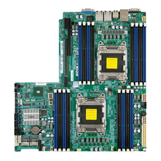
Checklist Congratulations on purchasing your computer motherboard from an acknowledged leader in the industry. Supermicro boards are designed with the utmost attention to detail to provide you with the highest standards in quality and performance. Please check that the following items have all been included with your motherboard. - Page 10 X9DRW-3F/X9DRW-iF Motherboard User’s Manual Motherboard Image Note: All graphics shown in this manual were based upon the latest PCB Revision available at the time of publishing of the manual. The motherboard you've received may or may not look exactly the same as the graphics...
-
Page 11: Motherboard Layout
Note 1: Changing BMC log-in information is recommended during initial system power-on. The default username is ADMIN and password is ADMIN. For BMC best practices, please refer to: http://www.supermicro. com/products/nfo/files/IPMI/Best_Practices_BMC_Security.pdf Note 2: " " indicates the location of "Pin 1". -
Page 12: Default Setting
X9DRW-3F/X9DRW-iF Motherboard User’s Manual X9DRW-3F/X9DRW-iF Quick Reference COM1 USB0/1 JUIDB CTRL LAN1 LAN2 USB2/3 IPMI-LAN JPW4 CPU2 CLOSE 1st OPEN 1st COM2 X9DRW-3F/iF Rev.1.02 CTRL JPW3 CPU1 JI2C1 JVRM_I2C1 JPG1 BIOS CLOSE 1st JVRM_I2C2 JPW2 JBT1 OPEN 1st JBAT1 SATA/... - Page 13 Chapter 1: Overview JPME2 Management Engine (ME) Pins 1-2 (Normal) Manufacture Mode Select JWD1 Watch Dog Pins 1-2 (Reset) X9DRW-3F/X9DRW-iF Connectors Connectors Description COM1/COM2 Backplane COM Port1/Front Accessible COM2 Header FAN1~4,FANA, FANB CPU/System Fan Headers I-SATA 0~5 Intel PCH SATA Connectors 0~5 JBAT1 Onboard Battery (See Chpt.
- Page 14 24-pin and the 8-pin power connectors to your power supply for adequate power delivery to your system. The 4-pin power connector is optional; however, Supermicro recommends that this connector also be plugged in for optimal power delivery.
-
Page 15: Motherboard Features
Note 1: 1866 MHz memory speed is dependent on Intel E5-2600v2 CPUs. Note 2: For the latest memory updates, please refer to the Tested Memory List posted on our website (http://www.supermicro.com/products/ motherboard). • Virtualization: VT-x, VT-d, and VT-c •... -
Page 16: Peripheral Devices
X9DRW-3F/X9DRW-iF Motherboard User’s Manual • RAID (Linux) RAID 0, 1, 10 SAS/SATA/SCU Connection • Eight (8) SAS/SATA Connections 0~3, 4~7 (For X9DRW-3F) RAID 0, 1, 10 • Four (4) SATA Connections 0~3 (For X9DRW-iF) RAID 0, 1, 5, 10 IPMI 2.0 •... - Page 17 Note 1: For IPMI Configuration Instructions, please refer to the Embedded IPMI Configuration User's Guide available @ http://www.supermicro.com/ support/manuals/. Note 2: Changing BMC log-in information is recommended during initial system power-on. The default username is ADMIN and password is ADMIN. For BMC best practices, please refer to: http://www.supermicro.com/products/ nfo/files/IPMI/Best_Practices_BMC_Security.pdf...
-
Page 18: System Block Diagram
X9DRW-3F/X9DRW-iF Motherboard User’s Manual Right Slot PCIE 3.0x16 PE2 PE1 CPU Rear Socket 01 PROCESSOR CPU Front Socket 00 PROCESSOR BIOS P0PE3 SPI Flash Lane Reversal & Polarity Inversion DMI: Lane Reversal Left Slot PCIE 3.0x16+x16 SATA [0...5] PEG [0...3]... -
Page 19: Processor And Chipset Overview
3F/X9DRW-iF motherboard provides the performance and feature sets required for dual_processor-based, high-performance WIO platforms. With support of Intel QuickPath interconnect (QPI) Technology, the X9DRW-3F/ X9DRW-iF motherboard offers point-to-point serial interconnect interface with a transfer speed of up to 8.0 GT/s, providing superb system performance. -
Page 20: Special Features
X9DRW-3F/X9DRW-iF Motherboard User’s Manual Special Features Recovery from AC Power Loss The Basic I/O System (BIOS) provides a setting that determines how the system will respond when AC power is lost and then restored to the system. You can choose for the system to remain powered off (in which case you must press the power switch to turn it back on), or for it to automatically return to the power-on state. -
Page 21: Acpi Features
24-pin and the 8-pin power connectors to your power supply for adequate power delivery to your system. The 4-pin power connector is optional; however, Supermicro recommends that this connector also be plugged in for optimal power delivery. -
Page 22: Super I/O
X9DRW-3F/X9DRW-iF Motherboard User’s Manual filter to shield the computer from noise. It is recommended that you also install a power surge protector to help avoid problems caused by power surges. Super I/O The Super I/O provides functions that comply with ACPI (Advanced Configuration and Power Interface), which includes support of legacy and ACPI power manage- ment through an SMI or SCI function pin. -
Page 23: Bmc Subsystem Features
Chapter 1: Overview offers a 4-way full-associative instruction TBL (Translation Lookaside Buffer) and a 64-way full-associative shared TBL. The memory management unit, which is embed- ded on the chip, provides access to 4 Gb virtual address space. In addition, this controller also supports 32 Kb on-chip SRAM, allowing for faster access which is especially critical to time-sensitive, high-density/high-performance server platforms. - Page 24 X9DRW-3F/X9DRW-iF Motherboard User’s Manual Notes 1-16...
-
Page 25: Chapter 2 Installation
The following statements are industry-standard warnings, provided to warn the user of situations which have the potential for bodily injury. Should you have questions or experience difficulty, contact Supermicro's Technical Support department for assis- tance. Only certified technicians should attempt to install or configure components. - Page 26 X9DRW-3F/X9DRW-iF Motherboard User’s Manual Attention Danger d'explosion si la pile n'est pas remplacée correctement. Ne la remplacer que par une pile de type semblable ou équivalent, recommandée par le fabricant. Jeter les piles usagées conformément aux instructions du fabricant. ¡Advertencia! Existe peligro de explosión si la batería se reemplaza de manera incorrecta.
-
Page 27: Product Disposal
Chapter 2: Installation Product Disposal Warning! Ultimate disposal of this product should be handled according to all national laws and regulations. 製品の廃棄 この製品を廃棄処分する場合、 国の関係する全ての法律 ・ 条例に従い処理する必要が あります。 警告 本产品的废弃处理应根据所有国家的法律和规章进行。 警告 本產品的廢棄處理應根據所有國家的法律和規章進行。 Warnung Die Entsorgung dieses Produkts sollte gemäß allen Bestimmungen und Gesetzen des Landes erfolgen. -
Page 28: Static-Sensitive Devices
X9DRW-3F/X9DRW-iF Motherboard User’s Manual القىانين واللىائح الىطنية جميع وفقا ل ينبغي التعامل معه هذا المنتج من التخلص النهائي عند 경고! 이 제품은 해당 국가의 관련 법규 및 규정에 따라 폐기되어야 합니다. Waarschuwing De uiteindelijke verwijdering van dit product dient te geschieden in overeenstemming met alle nationale wetten en reglementen. -
Page 29: Processor And Heatsink Installation
CPU socket cap is in place and none of the socket pins are bent; otherwise, contact your retailer immediately. • Refer to the Supermicro website for updates on CPU support. Installing the LGA2011 Processor 1. There are two load levers on the LGA2011 socket. To open the socket cover, first press and release the load lever labeled 'Open 1st'. - Page 30 X9DRW-3F/X9DRW-iF Motherboard User’s Manual 1. Press the second load lever labeled 'Close 1st' to release the load plate that covers the CPU socket from its locking position. Press down on Load Pull lever away from Lever 'Close 1st' the socket 2.
- Page 31 Chapter 2: Installation 1. Using your thumb and the index finger, remove the 'WARNING' plastic cap from the socket. 2. Use your thumb and index finger to hold the CPU on its edges. Align the CPU keys, which are semi-circle cutouts, against the socket keys. Socket Keys CPU Keys 3.
- Page 32 X9DRW-3F/X9DRW-iF Motherboard User’s Manual 1. With the CPU inside the socket, inspect the four corners of the CPU to make sure that the CPU is properly installed. 2. Close the load plate with the CPU inside the socket. Lock the lever labeled 'Close 1st' first, then lock the lever labeled 'Open 1st'.
-
Page 33: Installing A Passive Cpu Heatsink
3. Hold the heatsink as shown in the picture below, and gently wriggle the heat- sink to loosen it. (Do not use excessive force when wriggling the heatsink.) Note: For instructions on CPU/Heatsink installation and removal, please refer to the CPU/Heatsink Instructions posted on our website at http://www. supermicro.com/support/manuals/. -
Page 34: Installing And Removing The Memory Modules
Installing and Removing the Memory Modules Note: Check Supermicro's website for recommended memory modules. CAUTION Exercise extreme care when installing or removing DIMM modules to prevent any possible damage. -
Page 35: Removing Memory Modules
"B", before installing a DIMM module into P1-DIMMA1. COM1 USB0/1 JUIDB CTRL LAN2 LAN1 USB2/3 JPW4 IPMI-LAN CPU2 CLOSE 1st OPEN 1st COM2 X9DRW-3F/iF Rev.1.02 CTRL JPW3 CPU1 JI2C1 JVRM_I2C1 JPG1 BIOS CLOSE 1st JVRM_I2C2 JPW2 JBT1 OPEN 1st... - Page 36 X9DRW-3F/X9DRW-iF Motherboard User’s Manual Memory Support for the X9DRW-3F/X9DRW-iF Motherboard The X9DRW-3F/X9DRW-iF motherboard supports up to 1 TB of Load Reduced (LRDIMM), 512 GB of Registered (RDIMM) or 128 GB of Unbuffered (UDIMM) ECC/Non-ECC DDR3 800/1066/1333/1600/1866 MHz 240-pin 4-channel memory modules in 16 DIMM slots.
- Page 37 1600 1866 1866 Note: For detailed information on memory support and updates, please refer to the SMC Recommended Memory List posted on our website at http://www.supermicro.com/support/resources/mem.cfm. Populating RDIMM (ECC) Memory Modules Intel E5-2600(v2) Series Processor RDIMM Memory Support Ranks Memory Capacity...
- Page 38 1333, 1333 1333 Note: For detailed information on memory support and updates, please refer to the SMC Recommended Memory List posted on our website at http://www.supermicro.com/support/resources/mem.cfm. Populating RDIMM (ECC) Memory Modules Intel E5-2600 Series Processor RDIMM Memory Support Ranks Memory Capacity...
- Page 39 1066 1066 (QDP) Note: For detailed information on memory support and updates, please refer to the SMC Recommended Memory List posted on our website at http://www.supermicro.com/support/resources/mem.cfm. Intel E5-2600 Series Processor LRDIMM Memory Support Ranks Memory Speed (MT/s) and Voltage Validated by Slot per Channel (SPC) and DIMM Per...
- Page 40 X9DRW-3F/X9DRW-iF Motherboard User’s Manual Possible System Memory Allocation & Availability System Device Size Physical Memory Remaining (-Available) (4 GB Total System Memory) Firmware Hub flash memory (System BIOS) 1 MB 3.99 Local APIC 4 KB 3.99 Area Reserved for the chipset 2 MB 3.99...
-
Page 41: Motherboard Installation
There are seven (7) mounting holes on this motherboard indicated by the arrows. COM1 USB0/1 JUIDB CTRL LAN1 LAN2 USB2/3 IPMI-LAN JPW4 CPU2 CLOSE 1st OPEN 1st COM2 X9DRW-3F/iF Rev.1.02 CTRL JPW3 CPU1 JI2C1 JVRM_I2C1 JPG1 BIOS CLOSE 1st JVRM_I2C2 JPW2 JBT1 OPEN 1st... -
Page 42: Installing The Motherboard
X9DRW-3F/X9DRW-iF Motherboard User’s Manual Installing the Motherboard 1. Install the I/O shield into the chassis. 2. Locate the mounting holes on the motherboard. 3. Locate the matching mounting holes on the chassis. Align the mounting holes on the motherboard with the mounting holes on the chassis. -
Page 43: Control Panel Connectors And I/O Ports
I/O ports. Back Panel Connectors and I/O Ports COM1 USB0/1 JUIDB CTRL LAN1 LAN2 USB2/3 IPMI-LAN JPW4 CPU2 CLOSE 1st OPEN 1st COM2 X9DRW-3F/iF Rev.1.02 CTRL JPW3 CPU1 JI2C1 JVRM_I2C1 JPG1 BIOS JVRM_I2C2 CLOSE 1st JPW2 JBT1 OPEN 1st JBAT1... -
Page 44: Universal Serial Bus (Usb)
X9DRW-3F/X9DRW-iF Motherboard User’s Manual Universal Serial Bus (USB) FP USB (4/5) Backplane USB Pin Definitions (USB 0/1, 2/3) Four Universal Serial Bus ports (USB Pin Definitions USB 4 USB 5 0/1, 2/3) are located on the I/O back Pin # Definition Pin # Definition Pin# Definition panel. -
Page 45: Serial Ports
1. COM1 COM1 USB0/1 JUIDB 2. COM2 CTRL LAN2 LAN1 USB2/3 IPMI-LAN JPW4 3. VGA1 CPU2 CLOSE 1st OPEN 1st COM2 X9DRW-3F/iF Rev.1.02 CTRL JPW3 CPU1 JI2C1 JVRM_I2C1 JPG1 BIOS CLOSE 1st JVRM_I2C2 JPW2 JBT1 OPEN 1st JBAT1 SCU0~3 SATA/SCU4~7... -
Page 46: Ethernet Ports
X9DRW-3F/X9DRW-iF Motherboard User’s Manual Ethernet Ports LAN Ports Pin Definition Two Gigabit Ethernet ports (LAN1/2) Pin# Definition are located on the I/O backplane on P2V5SB SGND the motherboard to provide internet TD0+ Act LED connections. In addition, an IPMI_ TD0- P3V3SB... -
Page 47: Unit Identifier Switch
USB0/1 2. Rear UID LED (LED3) JUIDB CTRL LAN2 LAN1 USB2/3 IPMI-LAN JPW4 3. Front UID LED CPU2 CLOSE 1st OPEN 1st COM2 X9DRW-3F/iF Rev.1.02 CTRL JPW3 CPU1 JI2C1 JVRM_I2C1 JPG1 BIOS CLOSE 1st JVRM_I2C2 JPW2 JBT1 OPEN 1st JBAT1... -
Page 48: Front Control Panel
These connectors are designed specifically for use with Supermicro's server chassis. See the figure below for the descriptions of the various control panel buttons and LED indicators. Refer to the following section for descriptions and pin definitions. -
Page 49: Front Control Panel Pin Definitions
CLOSE 1st FP PWRLED 3.3 V HDD LED ID_UID_SW/3/3V Stby OPEN 1st NIC1 Link LED NIC1 Activity LED COM2 X9DRW-3F/iF NIC2 Activity LED Rev.1.02 NIC2 Link LED CTRL JPW3 Blue+ (OH/Fan Fail/ CPU1 Red+ (Blue LED Cathode) PWR FaiL/UID LED) -
Page 50: Hdd Led
X9DRW-3F/X9DRW-iF Motherboard User’s Manual HDD LED HDD LED Pin Definitions (JF1) The HDD LED connection is located Pin# Definition on pins 13 and 14 of JF1. Attach a 3.3V Standby cable here to indicate HDD activ- HD Active ity. See the table on the right for pin definitions. -
Page 51: Overheat (Oh)/Fan Fail/Pwr Fail/Uid Led
CPU2 CLOSE 1st FP PWRLED 3.3 V HDD LED ID_UID_SW/3/3V Stby OPEN 1st NIC1 Link LED NIC1 Activity LED COM2 X9DRW-3F/iF NIC2 Activity LED Rev.1.02 NIC2 Link LED CTRL JPW3 Blue+ (OH/Fan Fail/ CPU1 Red+ (Blue LED Cathode) JI2C1 JVRM_I2C1... -
Page 52: Reset Button
X9DRW-3F/X9DRW-iF Motherboard User’s Manual Reset Button Reset Button Pin Definitions (JF1) The Reset Button connection is located Pin# Definition on pins 3 and 4 of JF1. Attach it to a Reset hardware reset switch on the computer Ground case. Refer to the table on the right for pin definitions. -
Page 53: Connecting Cables
Pin Definitions delivery to your system. The 4-pin power connector Pins Definition is optional; however, Supermicro recommends that 1 through 4 Ground this connector also be plugged in for optimal power 5 through 8 +12V delivery. -
Page 54: Fan Headers
X9DRW-3F/X9DRW-iF Motherboard User’s Manual Fan Headers Fan Header Pin Definitions This motherboard has six system/CPU Pin# Definition fan headers (Fan 1~Fan 4, Fan A, Fan B) Ground on the motherboard. All these 4-pin fans +12V headers are backward compatible with Tachometer the traditional 3-pin fans. -
Page 55: Internal Speaker
COM1 A. Internal Speaker (Buzz- USB0/1 JUIDB CTRL LAN1 LAN2 USB2/3 IPMI-LAN JPW4 B. OH LED CPU2 CLOSE 1st OPEN 1st COM2 X9DRW-3F/iF Rev.1.02 CTRL JPW3 CPU1 JI2C1 JVRM_I2C1 JPG1 BIOS CLOSE 1st JVRM_I2C2 JPW2 JBT1 OPEN 1st JBAT1 SCU0~3... -
Page 56: Standby Power Connector
X9DRW-3F/X9DRW-iF Motherboard User’s Manual Standby Power Connector Standby Power Pin Definitions The Standby Power connection head- Pin# Definition er is located at JSTBY1 on the moth- +5V Standby erboard. See the table on the right for Ground pin definitions. (You must also have a Wake-up cable to use this feature.) -
Page 57: Power Smb (I 2 C) Connector
No Connection A. JPI COM1 USB0/1 JUIDB B. IPMB CTRL LAN2 LAN1 USB2/3 JPW4 IPMI-LAN CPU2 CLOSE 1st OPEN 1st COM2 X9DRW-3F/iF Rev.1.02 CTRL JPW3 CPU1 JI2C1 JVRM_I2C1 JPG1 BIOS CLOSE 1st JVRM_I2C2 JPW2 JBT1 OPEN 1st JBAT1 SATA/ SCU0~3... -
Page 58: T-Sgpio 1/2 Headers
X9DRW-3F/X9DRW-iF Motherboard User’s Manual T-SGPIO 1/2 Headers T-SGPIO Pin Definitions Two SGPIO (Serial-Link General Pin# Definition Definition Purpose Input/Output) headers are located on the motherboard. These Ground Data headers support Serial_Link interface Load Ground for onboard SATA connections. See Clock the table on the right for pin defini- Note: NC= No Connection tions. -
Page 59: Power Led/Speaker
Pins 6-7 Internal Speaker A. PWR LED/Speaker COM1 USB0/1 JUIDB CTRL LAN1 LAN2 USB2/3 IPMI-LAN JPW4 CPU2 CLOSE 1st OPEN 1st COM2 X9DRW-3F/iF Rev.1.02 CTRL JPW3 CPU1 JI2C1 JVRM_I2C1 JPG1 BIOS CLOSE 1st JVRM_I2C2 JPW2 JBT1 OPEN 1st JBAT1 SATA/... -
Page 60: Jumper Settings
X9DRW-3F/X9DRW-iF Motherboard User’s Manual Jumper Settings Explanation of Jumpers Connector Pins To modify the operation of the mother- board, jumpers can be used to choose between optional settings. Jumpers cre- Jumper ate shorts between two pins to change the function of the connector. Pin 1... -
Page 61: Cmos Clear
A. Clear CMOS COM1 USB0/1 JUIDB B. Watch Dog Enable CTRL LAN1 LAN2 USB2/3 IPMI-LAN JPW4 CPU2 CLOSE 1st OPEN 1st COM2 X9DRW-3F/iF Rev.1.02 CTRL JPW3 CPU1 JI2C1 JVRM_I2C1 JPG1 BIOS JVRM_I2C2 CLOSE 1st JPW2 JBT1 OPEN 1st JBAT1 SCU0~3... -
Page 62: Vga Enable
X9DRW-3F/X9DRW-iF Motherboard User’s Manual VGA Enable VGA Enable Jumper Settings Jumper JPG1 allows the user to enable Jumper Setting Definition the onboard VGA connector. The default Enabled (Default) setting is 1-2 to enable the connection. Disabled See the table on the right for jumper settings. -
Page 63: Management Engine (Me) Recovery
JPME1 COM1 USB0/1 JUIDB B. JPME2 CTRL LAN1 LAN2 USB2/3 IPMI-LAN JPW4 CPU2 CLOSE 1st OPEN 1st COM2 X9DRW-3F/iF Rev.1.02 CTRL JPW3 CPU1 JI2C1 JVRM_I2C1 JPG1 BIOS CLOSE 1st JVRM_I2C2 JPW2 JBT1 OPEN 1st JBAT1 SATA/... - Page 64 X9DRW-3F/X9DRW-iF Motherboard User’s Manual C Bus to PCI-Exp. Slots C to PCI-Exp Jumper Settings Jumpers JI C1 and JI C2 allow you to Jumper Setting Definition connect the System Management Bus Closed Enabled C) to PCI-Express slots. The default Open...
-
Page 65: Onboard Led Indicators
A. Ethernet Port USB0/1 JUIDB CTRL LEDs LAN1 LAN2 USB2/3 IPMI-LAN JPW4 B. IPMI LAN LEDs CPU2 CLOSE 1st OPEN 1st COM2 X9DRW-3F/iF Rev.1.02 CTRL JPW3 CPU1 JI2C1 JVRM_I2C1 JPG1 BIOS CLOSE 1st JVRM_I2C2 JPW2 JBT1 OPEN 1st JBAT1 SATA/SCU4~7... -
Page 66: Onboard Power Led
X9DRW-3F/X9DRW-iF Motherboard User’s Manual Onboard Power LED Onboard PWR LED Indicator LED Settings An Onboard Power LED is located at LED Color Status LED2 on the motherboard. When this System Off (PWR cable not connected) LED is on, the system is on. Be sure to... -
Page 67: Bmc Heartbeat Led
A. BMC Heartbeat COM1 USB0/1 JUIDB CTRL LAN2 LAN1 USB2/3 IPMI-LAN JPW4 CPU2 CLOSE 1st OPEN 1st COM2 X9DRW-3F/iF Rev.1.02 CTRL JPW3 CPU1 JI2C1 JVRM_I2C1 JPG1 BIOS CLOSE 1st JVRM_I2C2 JPW2 JBT1 OPEN 1st JBAT1... -
Page 68: 2-10 Sata/Scu Connections
Ground cluding four SATA2 ports and two SATA3 TX_P ports. There are also eight SCU ports TX_N (0~3, 4~7) located on the X9DRW-3F, and Ground four SCU ports (SCU 0~3) located on the RX_N X9DRW-iF. These ports provide serial-link RX_P... -
Page 69: Chapter 3 Troubleshooting
Chapter 3: Troubleshooting Chapter 3 Troubleshooting Troubleshooting Procedures Use the following procedures to troubleshoot your system. If you have followed all of the procedures below and still need assistance, refer to the ‘Technical Support Procedures’ and/or ‘Returning Merchandise for Service’ section(s) in this chapter. Always disconnect the AC power cord before adding, changing or installing any hardware components. -
Page 70: System Boot Failure
X9DRW-3F/X9DRW-iF Motherboard User’s Manual No Video 1. If the power is on, but you have no video, remove all the add-on cards and cables. 2. Use the speaker to determine if any beep codes exist. Refer to Appendix A for details on beep codes. -
Page 71: Memory Errors
2. Memory support: Make sure that the memory modules are supported by test- ing the modules using memtest86 or a similar utility. Note: Refer to the product page on our website http://www.supermicro. com for memory and CPU support and updates. - Page 72 X9DRW-3F/X9DRW-iF Motherboard User’s Manual within the normal range. Also check the front panel Overheat LED, and make sure that the Overheat LED is not on. 5. Adequate power supply: Make sure that the power supply provides adequate power to the system. Make sure that all power connectors are connected.
-
Page 73: Technical Support Procedures
Before contacting Technical Support, please make sure that you have followed all the steps listed below. Also, Note that as a motherboard manufacturer, Supermicro does not sell directly to end users, so it is best to first check with your distributor or reseller for troubleshooting services. -
Page 74: Battery Removal And Installation
X9DRW-3F/X9DRW-iF Motherboard User’s Manual Battery Removal and Installation Battery Removal To remove the onboard battery, follow the steps below: 1. Power off your system and unplug your power cable. 2. Locate the onboard battery as shown below. 3. Using a tool such as a pen or a small screwdriver, push the battery lock out- wards to unlock it. -
Page 75: Frequently Asked Questions
Note : The SPI BIOS chip used on this motherboard cannot be removed. Send your motherboard back to our RMA Department at Supermicro for repair. For BIOS Recovery instructions, please refer to the AMI BIOS Recovery Instructions posted at http://www.supermicro.com. -
Page 76: Returning Merchandise For Service
X9DRW-3F/X9DRW-iF Motherboard User’s Manual Returning Merchandise for Service A receipt or copy of your invoice marked with the date of purchase is required before any warranty service will be rendered. You can obtain service by calling your ven- dor for a Returned Merchandise Authorization (RMA) number. When returning the... -
Page 77: Chapter 4 Bios
BIOS Introduction This chapter describes the AMI BIOS Setup utility for the X9DRW-3F/X9DRW-iF. It also provides the instructions on how to navigate the AMI BIOS Setup utility screens. The AMI ROM BIOS is stored in a Flash EEPROM and can be easily updated. -
Page 78: Main Setup
X9DRW-3F/X9DRW-iF Motherboard User’s Manual Warning: Do not upgrade the BIOS unless your system has a BIOS-related issue. Flashing the wrong BIOS can cause irreparable damage to the system. In no event shall the manufacturer be liable for direct, indirect, special, incidental, or consequential damage arising from a BIOS update. -
Page 79: 4-3 Advanced Setup Configurations
Chapter 4: AMI BIOS Memory Information Total Memory This displays the amount of memory that is available in the system. 4-3 Advanced Setup Configurations Use the arrow keys to select Advanced Setup and press <Enter> to access the following submenu items. Boot Features Quiet Boot This feature allows the user to select bootup screen display between POST mes- sages and the OEM logo. - Page 80 X9DRW-3F/X9DRW-iF Motherboard User’s Manual Wait For 'F1' If Error Select Enabled to force the system to wait until the 'F1' key is pressed if an error occurs. The options are Disabled and Enabled. Interrupt 19 Capture Interrupt 19 is the software interrupt that handles the boot disk function. When this item is set to Enabled, the ROM BIOS of the host adaptors will "capture"...
- Page 81 Chapter 4: AMI BIOS • Type of CPU • CPU Signature • Microcode Patch • CPU Stepping • Maximum CPU Speed • Minimum CPU Speed • Processor Cores • Intel HT (Hyper-Threading) Technology • Intel VT-x Technology • Intel SMX Technology •...
- Page 82 X9DRW-3F/X9DRW-iF Motherboard User’s Manual Active Processor Cores Set to Enabled to use a processor's second core and above. (Please refer to Intel's website for more information.) The options are All, 1, 2, and 4. Limit CPUID Maximum This feature allows the user to set the maximum CPU ID value. Enable this function to boot the legacy operating systems that cannot support processors with extended CPUID functions.
- Page 83 Chapter 4: AMI BIOS Intel® Virtualization Technology (Available when supported by the CPU) Select Enabled to support Intel Virtualization Technology, which will allow one platform to run multiple operating systems and applications in independent parti- tions, creating multiple "virtual" systems in one physical computer. The options are Enabled and Disabled.
- Page 84 X9DRW-3F/X9DRW-iF Motherboard User’s Manual CPU C6 Report (Available when Power Technology is set to Custom) Select Enabled to allow the BIOS to report the CPU C6 State (ACPI C3) to the operating system. During the CPU C6 State, the power to all cache is turned off.
-
Page 85: North Bridge
Chapter 4: AMI BIOS Chipset Configuration North Bridge This feature allows the user to configure the settings for the Intel North Bridge. Integrated IO Configuration Intel VT-d Select Enabled to enable Intel Virtualization Technology support for Direct I/O VT-d by reporting the I/O device assignments to the VWM (Virtual Working Memory) through the DMAR ACPI Tables. - Page 86 X9DRW-3F/X9DRW-iF Motherboard User’s Manual QPI Configuration Current QPI Link This item displays the current status of the QPI Link. Current QPI Frequency This item displays the frequency of the QPI Link. Isoc Select Enabled to enable Isochronous support to meet QoS (Quality of Service) requirements.
- Page 87 Chapter 4: AMI BIOS DIMM Information The status of the memory modules specified below will be displayed as detected by the BIOS. CPU Socket 1 DIMM Information P1-DIMMA1/P1-DIMMB1/P1-DIMMC1/P1-DIMMD1/P1-DIMMA2/P1-DIMMB2/ P1-DIMMC2/P1-DIMMD2 CPU Socket 2 DIMM Information P2-DIMME1/P2-DIMMF1/P2-DIMMG1/P2-DIMMH1/P2-DIMME2/P2-DIMMF2/ P2-DIMMG2/P2-DIMMH2 Memory Mode When Independent is selected, all DIMMs are available to the operating system. When Mirroring is selected, the motherboard maintains two identical copies of all data in memory for data backup.
- Page 88 X9DRW-3F/X9DRW-iF Motherboard User’s Manual processing. By using this method, roughly 64 GB of memory behind the IO hub will be scrubbed every day. The options are Enabled and Disabled. Demand Scrub Demand Scrubbing is a process that allows the CPU to correct correctable memory errors found on a memory module.
- Page 89 Chapter 4: AMI BIOS EHCI Controller 1/EHCI Controller 2 (Available when All USB Devices are set to Enabled) Select Enabled to enable EHCI (Enhanced Host Controller Interface) Controller 1 or Controller 2. The options are Disabled and Enabled. Legacy USB Support (Available when USB Functions is not Disabled) Select Enabled to support legacy USB devices.
- Page 90 X9DRW-3F/X9DRW-iF Motherboard User’s Manual AHCI Mode The following items are displayed when the AHCI Mode is selected. Aggressive Link Power Management Select Enabled to enable Aggressive Link Power Management support for Cougar Point B0 stepping and beyond. The options are Enabled and Disabled.
- Page 91 Chapter 4: AMI BIOS PCI Latency Timer Use this feature to set the latency Timer of each PCI device installed on a PCI bus. Select 64 to set the PCI latency to 64 PCI clock cycles. The options are 32, 64, 96, 128, 160, 192, 224 and 248.
- Page 92 X9DRW-3F/X9DRW-iF Motherboard User’s Manual Onboard LAN Option ROM Select Select iSCSI to use the iSCSI Option ROM to boot the computer using a network device. Select PXE (Preboot Execution Environment) to use an PXE Option ROM to boot the computer using a network device. The options are iSCSI and PXE.
-
Page 93: Serial Port Console Redirection
Chapter 4: AMI BIOS Serial Port 2 Configuration Serial Port Select Enabled to enable a serial port specified by the user. The options are En- abled and Disabled. Device Settings This item displays the settings of Serial Port 2. Change Settings This option specifies the base I/O port address and the Interrupt Request address of Serial Port 1 and Serial Port 2. - Page 94 X9DRW-3F/X9DRW-iF Motherboard User’s Manual Bits Per second Use this feature to set the transmission speed for a serial port used in Console Redirection. Make sure that the same speed is used in the host computer and the client computer. A lower transmission speed may be required for long and busy lines.
-
Page 95: Acpi Setting
Chapter 4: AMI BIOS Legacy OS Redirection Use this feature to select the number of rows and columns used in Console Redirection for legacy OS support. The options are 80x24 and 80x25. Putty KeyPad This feature selects Function Keys and KeyPad settings for Putty, which is a terminal emulator designed for the Windows OS. - Page 96 X9DRW-3F/X9DRW-iF Motherboard User’s Manual Trusted Computing (Available when a TPM device is detected by the BIOS) Configuration TPM Support Select Enabled on this item and enable the TPM jumper on the motherboard to enable TPM support to improve data integrity and network security. The options are Enabled and Disabled.
-
Page 97: Add An Attempt
Chapter 4: AMI BIOS TXT (LT-SX) Support: This item indicated if the Intel TXT support is enabled or disabled. Intel TXT (LT-SX) Dependencies This feature displays the features that need to be enabled for the Intel Trusted Execution Technology to work properly in the system. VT-d Support: Intel Virtualization Technology with Direct I/O support VT Support: Intel Virtualization Technology support TPM Support: Trusted Platform support... -
Page 98: Change Attempt Order
X9DRW-3F/X9DRW-iF Motherboard User’s Manual Change Attempt Order Commit Changes and Exit Save the changes and exit from the page. Discard Changes and Exit Discard the changes and exit from the page. Intel® I350 Gigabit Network Connections: These items display the following information on the Intel I350 LAN connections. -
Page 99: Event Logs
Chapter 4: AMI BIOS • Alternate MAC Address Event Logs Use this feature to configure Event Log settings. Change SMBIOS Event Log Settings This feature allows the user to configure SMBIOS Event settings. Enabling/Disabling Options SMBIOS Event Log Select Enabled to enable SMBIOS (System Management BIOS) Event Logging during system boot. - Page 100 X9DRW-3F/X9DRW-iF Motherboard User’s Manual Erasing Settings Erase Event Log Select Enabled to erase the SMBIOS (System Management BIOS) Event Log, which is completed before a event logging is initialized upon system reboot. The options are No; Yes, next Reset; and Yes, every reset.
-
Page 101: Ipmi
Chapter 4: AMI BIOS IPMI Use this feature to configure Intelligent Platform Management Interface (IPMI) settings. IPMI Firmware Revision This item indicates the IPMI firmware revision used in your system. IPMI Status This item indicates the status of the IPMI firmware installed in your system. System Event Log ... - Page 102 X9DRW-3F/X9DRW-iF Motherboard User’s Manual When SEL is Full This feature allows the user to decide what the BIOS should do when the system event log is full. Select Erase Immediately to erase all events in the log when the system event log is full. The options are Do Nothing and Erase Immediately.
-
Page 103: Boot
Chapter 4: AMI BIOS Gateway IP Address This item displays the Gateway IP address for this computer. This should be in decimal and in dotted quad form (i.e., 192.168.10.253). Boot This submenu allows the user to configure the following boot settings for the system. -
Page 104: Security
X9DRW-3F/X9DRW-iF Motherboard User’s Manual Network Drives Boot Option #1 This item displays the first boot device. Delete Boot Options Delete Boot Option This item allows the user to select a boot device to delete from the boot priority list. Select UEFI: Built-in EFI Shell to delete it from the boot priority list which will prevent system boot from the UEFI Shell. -
Page 105: Save & Exit
Chapter 4: AMI BIOS Save & Exit This submenu allows the user to configure the Save and Exit settings for the system. Discard Changes and Exit Select this option to quit the BIOS Setup without making any permanent changes to the system configuration, and reboot the computer. Select Discard Changes and Exit, and press <Enter>. - Page 106 X9DRW-3F/X9DRW-iF Motherboard User’s Manual Discard Changes Select this feature and press <Enter> to discard all the changes and return to the BIOS setup. When the dialog box appears, asking you if you want to load previ- ous values, click Yes to load the values previous saved, or click No to keep the changes you've made so far.
-
Page 107: Appendix A Bios Error Beep Codes
Appendix A: BIOS POST Error Codes Appendix A BIOS Error Beep Codes During the POST (Power-On Self-Test) routines, which are performed at each system boot, errors may occur. Non-fatal errors are those which, in most cases, allow the system to continue to boot. - Page 108 X9DRW-3F/X9DRW-iF Motherboard User’s Manual Notes...
-
Page 109: Appendix B Software Installation Instructions
To install these programs, click the icons to the right of these items. Note: To install the Windows OS, please refer to the instructions posted on our Website at http://www.supermicro.com/support/manuals/. Driver/Tool Installation Display Screen Note 1: Click the icons showing a hand writing on the paper to view the readme files for each item. -
Page 110: Configuring Superdoctor® Iii
X9DRW-3F/X9DRW-iF Motherboard User’s Manual Note 3: Changing BMC log-in information is recommended during initial system power-on. The default username is ADMIN and password is ADMIN. For BMC best practices, please refer to: http://www.supermicro. com/products/nfo/files/IPMI/Best_Practices_BMC_Security.pdf B-2 Configuring SuperDoctor III The SuperDoctor® III program is a web-based management tool that supports remote management capability. - Page 111 Appendix B: Software Installation Instructions SuperDoctor® III Interface Display Screen-II (Remote Control) The SDIII utility and the user guide can be downloaded from our web- site at: http://www.supermicro.com/products/accessories/software/ SuperDoctorIII.cfm. For Linux, we will still recommend that you use SuperDoctor II.
- Page 112 X9DRW-3F/X9DRW-iF Motherboard User’s Manual Notes...
- Page 113 (Disclaimer Continued) The products sold by Supermicro are not intended for and will not be used in life support systems, medical equipment, nuclear facilities or systems, aircraft, aircraft devices, aircraft/emergency communication devices or other critical systems whose failure to perform be reasonably expected to result in significant injury or loss of life or catastrophic property damage.
Need help?
Do you have a question about the X9DRW-3F and is the answer not in the manual?
Questions and answers