Sign In
Upload
Download
Table of Contents
Contents
Add to my manuals
Delete from my manuals
Share
URL of this page:
HTML Link:
Bookmark this page
Add
Manual will be automatically added to "My Manuals"
Print this page
×
Bookmark added
×
Added to my manuals
Manuals
Brands
Supermicro Manuals
Motherboard
Supero X9SRH-7TF
User manual
Supermicro Supero X9SRH-7TF User Manual
Hide thumbs
1
2
3
4
5
Table Of Contents
6
7
8
9
10
11
12
13
14
15
16
17
18
19
20
21
22
23
24
25
26
27
28
29
30
31
32
33
34
35
36
37
38
39
40
41
42
43
44
45
46
47
48
49
50
51
52
53
54
55
56
57
58
59
60
61
62
63
64
65
66
67
68
69
70
71
72
73
74
75
76
77
78
79
80
81
82
83
84
85
86
87
88
89
90
91
92
93
94
95
96
97
98
99
100
101
102
103
104
105
106
107
108
109
110
111
112
113
114
115
page
of
115
Go
/
115
Contents
Table of Contents
Troubleshooting
Bookmarks
Table of Contents
About this Motherboard
Manual Organization
Conventions Used in the Manual
Safety Information
Contacting Supermicro
Table of Contents
Chapter 1 Introduction
Overview
Checklist
Motherboard Features
System Block Diagram
Chipset Overview
Intel C602J Chipset Series Features
Special Features
Recovery from AC Power Loss
PC Health Monitoring
Fan Status Monitor with Firmware Control
Environmental Temperature Control
System Resource Alert
ACPI Features
Slow Blinking LED for Suspend-State Indicator
Power Supply
Super I/O
Overview of the Nuvoton WPCM450 Controller
Chapter 2 Installation
Static-Sensitive Devices
Precautions
Unpacking
Processor and Heatsink Installation
The LGA2011 Socket
Opening the LGA2011 Socket
Installing the LGA2011 Processor
Installing a Passive CPU Heatsink
Removing the Heatsink
Installing DDR3 Memory
DIMM Installation
Removing Memory Modules
Memory Support
Memory Population Guidelines
Motherboard Installation
Tools Needed
Location of Mounting Holes
Installing the Motherboard
Connectors/Io Ports
Motherboard I/O Backpanel
ATX PS/2 Keyboard/Mouse Ports
Universal Serial Bus (USB)
Ethernet Ports
Serial Ports
Video Port
Front Control Panel
Front Control Panel Pin Definitions
Hdd Led
Power Fail LED
Power LED
Nic1/Nic2 (Lan1/Lan2)
Overheat (Oh)/Fan Fail / UID LED
NMI Button
Power Button
Reset Button
Connecting Cables & Optional Devices
ATX Main PWR (JPW1) & CPU PWR Connectors (JPW2)
Fan Headers (FAN1~4, FANA)
Chassis Intrusion (JL1)
Speaker (JD1)
Internal Buzzer (SP1)
Wake-On-LAN (JSTBY1)
Power Supply I
C (Jpi2C1)
DOM PWR Connector (JSD1)
T-SGPIO 1/2 & 6-SGPIO 1/2 Headers
TPM Header (JTPM1)
Unit ID Switch (UID SW)
Overheat/Fan Fail LED (JOH1 )
System Management Bus (JIPMB1 )
Wake-On-Ring
RAID Key Header (JRK1 )
Jumper Settings
Explanation of Jumpers
LAN Port Enable/Disable (JPL1~2)
CMOS Clear (JBT1)
PCI-E Slot SMB Enable (JI2C1/JI2C2)
VGA Enable (JPG1)
Watch Dog Reset (JWD1)
BMC Enable/Disable (JPB1)
USB Wake-Up (JPUSB1)
ME Manufacturing Mode (JPME2)
ME Recovery (JPME1)
SAS Enable/Disable (JPS1)
Onboard Indicators
LAN Port Leds
IPMI Dedicated LAN Leds
Rear Unit ID LED (UID LED)
IPMI Heartbeat LED (DP3)
Onboard Power LED (DP2)
SATA and SAS Connections
SATA/SAS Connections
Chapter 3 Troubleshooting
Troubleshooting Procedures
Before Power on
No Power
No Video
Memory Errors
When You Lose The System's Setup Configuration
Technical Support Procedures
Frequently Asked Questions
Battery Removal and Installation
Battery Removal
Proper Battery Disposal
Battery Installation
Returning Merchandise for Service
Chapter 4 BIOS
Introduction
Starting BIOS Setup Utility
How to Start the Setup Utility
Main Setup
System Overview: the Following BIOS Information will be Displayed
System Date/System Time
Supermicro X9SRH-7F/7TF
Memory Information
Total Memory
4-3 Advanced Setup Configurations
BOOT Feature
Addon ROM Display Mode
Bootup Num-Lock
Interrupt 19 Capture
Quiet Boot
Wait for 'F1' if Error
Clock Spread Spectrum
CPU Configuration
Power Button Function
Restore on AC Power Loss
Retry Boot
Socket 1 CPU Information
Watch Dog Function
Active Processor Cores
DCU IP Prefetcher
DCU Streamer Prefetcher
Execute-Disable Bit (if Supported by the os and the CPU)
Hyper Threading
Intel® AES-NI (if Supported by the CPU)
Limit CPUID Maximum
MLC Spatial Prefetch (if Supported by the CPU)
MLC Streamer Prefetcher (if Supported by the CPU)
CPU Power Management Configuration
Eist
Intel ® Virtualization Technology (if Supported by the CPU)
Power Technology
Turbo Mode (Available When EIST Is Set to Enabled)
C1E Support
CPU C3 Report, CPU C6, CPU C7 Report
Package C State Limit
Energy/Performance Bias
Long Duration Power Limit
Chipset Configuration
North Bridge Configuration
Integrated IO Configuration
Intel ® VT-D
Intel ® I/OAT
DCA Support
Mmcfg Base
IIO 1 Pcie Port Bifurcation Control
CPU1 Slot 3 PCI-E 3.0 X8 (in X16) Link Speed
CPU1 Slot 6 PCI-E 3.0 X16 Link Speed
DIMM Configuration
Memory Configuration
DIMM Information
Memory Mode
DRAM RAPL Mode
DDR Speed
Channel Interleaving
Rank Interleaving
Patrol Scrub
Demand Scrub
Data Scrambling
Device Tagging
Thermal Throttling
South Bridge Configuration
All USB Devices
EHCI Controller 1 / EHCI Controller 2
Legacy USB Support
Port 60/64 Emulation
EHCI Hand-Off
SATA Configuration
SATA Port0~Port5
SATA Mode
IDE Mode
Serial-ATA Controller 0~1
AHCI Mode
Aggressive Link Power Management
Port 0~5 Hot Plug
Port 0~5 Staggered Spin up
RAID Mode
SATA RAID Option ROM/UEFI Driver
Pcie/Pci/Pnp Configuration
Launch Storage Oprom Policy
PCI Latency Timer
PERR# Generation
SERR# Generation
Maximum Payload
Maximum Read Request
ASPM Support
Above 4G Decoding
Slot1 PCI 33MHZ OPROM
Slot2 PCI 33MHZ OPROM
CPU1 Slot3 PCI-E 3.0 X8 (in X16) OPROM
Slot4 PCI 33Mhz OPROM (X9SRH-7F Only)
PCH Slot5 PCI-E 2.0 X4 OPROM
CPU1 Slot6 PCI-E 3.0 X16 OPROM
Onboard LAN Option ROM Select
Load Onboard LAN1 Option ROM / Load Onboard LAN2 Option ROM
VGA Priority
Network Stack
Serial Port Console Redirection
ACPI Settings
High Precision Event Timer
Trusted Computing
Intel TXT(LT-SX) Configuration
Cpu/Chipset TXT Feature
TXT Support
Intel TXT(LT-SX) Dependencies
ME Subsystem
Iscsi Configuration
Add an Attempt
Iscsi Initiator Name
Blink Leds (Range 0-15 Seconds)
Change Attempt Order
Delete Attempts
Intel(R) Intel Ethernet Controller X540-AT2
Link Speed
Nic Configuration
Port Configuration Information
Wake on LAN
Change Smbios Event Log Settings
Erase Event Log
Memory Correction Error Threshold
PCI Error Logging Support
Runtime Error Logging Support
Smbios Event Log
When Log Is Full
Log System Boot Event
Meci
Metw
View Smbios Event Log
Ipmi
System Event Log
When SEL Is Full
BMC Network Configuration
Update Ipmi Lan Configuration
Configuration Address Source
Boot Settings
Set Boot Priority
1St Boot Device, 2Nd Boot Device, 3Rd Boot Device, Etc
Add Boot Option
Network Devices, USB Device BBS Priorities, Hard Disk Drives
Password Check
Security Settings
Administrator Password
Save & Exit
Discard Changes and Exit
Save Changes and Reset
Save Changes
Discard Changes
Restore Optimized Defaults
Save as User Defaults
Restore User Defaults
Boot Override
Appendix A
A-1 BIOS Error Beep Codes
Appendix B Software Installation Instructions
B-1 Installing Drivers
Configuring Superdoctor ® III
An Overview to the UEFI BIOS
Appendix C UEFI BIOS Recovery Instructions
How to Recover the UEFI BIOS Image (-The Main BIOS Block
To Recover the Main BIOS Block Using a USB-Attached Device
Advertisement
Quick Links
1
Motherboard Features
2
Cmos Clear (Jbt1)
Download this manual
X9SRH-7F
X9SRH-7TF
USER'S MANUAL
Revision 1.0
Table of
Contents
Previous
Page
Next
Page
1
2
3
4
5
Advertisement
Table of Contents
Need help?
Do you have a question about the Supero X9SRH-7TF and is the answer not in the manual?
Ask a question
Questions and answers
Related Manuals for Supermicro Supero X9SRH-7TF
Motherboard Supermicro Supero X9SRi User Manual
(109 pages)
Motherboard Supermicro X9SRi3F Quick Reference Manual
(1 page)
Motherboard Supermicro Supero X9SRH-7F User Manual
(115 pages)
Motherboard Supermicro X9SRW-F User Manual
X9srw series (104 pages)
Motherboard Supermicro X9SRW-F Quick Reference Manual
(1 page)
Motherboard Supermicro Supero X9SPU-F User Manual
(107 pages)
Motherboard Supermicro Supero X9SCA User Manual
Super micro - x9sca server motherboard (107 pages)
Motherboard Supermicro Supero X9SCi-LN4 User Manual
(107 pages)
Motherboard Supermicro Supero X9SCi-LN4 User Manual
(105 pages)
Motherboard Supermicro X9SCA Quick Manual
Workstation/server mainboard (38 pages)
Motherboard Supermicro Supero X9SCM-F User Manual
Super micro - x9scl-f desktop motherboard (105 pages)
Motherboard Supermicro Supero X9SCL-F User Manual
Super micro - x9scl-f desktop motherboard (105 pages)
Motherboard Supermicro X9SCM User Manual
Super micro - x9scl-f desktop motherboard (105 pages)
Motherboard Supermicro X9SKV Quick Reference Manual
(1 page)
Motherboard Supermicro X9DRW-3F User Manual
(109 pages)
Motherboard Supermicro X9QR7-TF+ User Manual
(111 pages)
Summarization of Contents
Introduction and Motherboard Overview
1-1 Overview: Checklist and Support Resources
Details the contents of the motherboard retail box and provides support links for drivers and manuals.
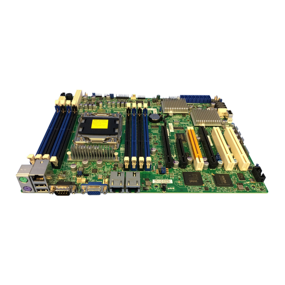
Motherboard Layout and Key Components
Illustrates the physical layout of the motherboard, highlighting connection points, jumpers, and headers.
Motherboard Features and Specifications
Lists and describes the key hardware features and specifications of the X9SRH motherboard series.
Chipset Overview: Intel C602J Features
Explains the capabilities and features of the Intel C602J chipset used on the motherboard.
Special Features: AC Power Loss & ACPI
Covers special motherboard features like AC power loss recovery and ACPI power management capabilities.
PC Health Monitoring: Temperature, Voltage, Fan Control
Describes the system's ability to monitor CPU temperature, voltages, and fan speeds via onboard sensors.
Power Supply Requirements and Connections
Specifies the necessary power supply and connector requirements for the motherboard and system stability.
Super I/O and Management Controller Overview
Details the Super I/O chip and the Nuvoton WPCM450 Baseboard Management Controller functions.
Hardware Installation Procedures
2-1 Static-Sensitive Device Handling Precautions
Outlines essential precautions for handling static-sensitive components to prevent damage during installation.
2-2 Processor and Heatsink Installation: LGA2011 Socket
Provides step-by-step instructions for installing the CPU and heatsink, including socket details.
Installing DDR3 Memory Modules: DIMM Procedures
Guides users on how to correctly install and remove DDR3 memory modules into the DIMM slots.
2-4 Motherboard Installation: Chassis Mounting Guide
Explains the process of physically mounting the motherboard into the computer chassis, including tools needed.
2-5 Connectors and I/O Ports: Backpanel and Headers
Identifies and describes the various connectors, ports, and headers on the motherboard's I/O panel and internal headers.
2-6 Connecting Cables: Power, Fans, and Optional Devices
Details how to connect power cables, fan headers, and other optional devices to the motherboard connectors.
2-7 Jumper Settings: System Configuration Options
Explains the function and configuration of various jumpers on the motherboard for system control and feature enabling/disabling.
2-8 Onboard Indicators: LEDs for System Status
Describes the function of onboard LEDs and indicators used for system status, network activity, and power.
2-9 SATA and SAS Storage Connections
Details the SATA and SAS connectors on the motherboard and their pin definitions for storage devices.
Troubleshooting and Technical Support
3-1 Troubleshooting Procedures: Startup and Hardware Issues
Provides systematic procedures to diagnose and resolve common system startup problems like no power or no video.
Memory Errors and Setup Configuration Troubleshooting
Addresses troubleshooting steps for memory errors and issues related to losing system setup configuration.
3-2 Technical Support Procedures and Contact Info
Outlines the steps to take before contacting technical support and provides relevant contact information and resources.
3-3 Frequently Asked Questions (FAQ)
Answers common questions regarding memory support, BIOS updates, and driver installation procedures.
3-4 Battery Removal and Installation: Safety Guide
Explains the safe procedure for removing and installing the motherboard battery, including disposal warnings.
3-5 Returning Merchandise for Service: Warranty Process
Details the process for returning products for warranty service, including RMA procedures and warranty coverage information.
BIOS Configuration and Settings
4-1 Introduction to AMI BIOS Setup Utility
Introduces the AMI BIOS Setup Utility and how to navigate its screens and basic functions.
How to Start the BIOS Setup Utility
Guides the user on how to access the BIOS setup utility during system boot.
4-2 Main Setup: System Information Display
Covers the main BIOS setup screen, displaying system overview information like date, time, and memory.
4-3 Advanced Setup: Boot Features and CPU Settings
Details advanced BIOS settings related to boot features, CPU configuration, and power management.
Chipset, DIMM, and Memory Configuration Options
Explains settings for chipset features, memory configuration, and various performance-tuning options.
South Bridge, SATA, PCIe, and USB Settings
Covers settings for south bridge features, SATA modes, and PCIe slot configurations.
4-4 Event Logs and SmBIOS Management
Explains how to manage system event logs and configure SmBIOS logging features for system diagnostics.
4-5 IPMI Configuration: System Logs and Network
Details Intelligent Platform Management Interface (IPMI) settings for system monitoring and management.
4-6 Boot Settings: Device Priority and Boot Options
Guides users on configuring boot device priority, boot options, and security settings.
4-7 Security Settings: Password Management
Covers BIOS security features, including password protection and access control settings.
4-8 Save & Exit: Managing BIOS Configuration
Describes how to save, discard, or restore BIOS settings, and exit the setup utility.
Appendices and Software Information
Appendix A: BIOS Error Beep Codes
Lists BIOS beep codes and their corresponding error messages for diagnosing POST failures.
Appendix B: Software Installation: Drivers and Utilities
Provides guidance on installing drivers and software utilities included with the motherboard, such as SuperDoctor III.
Appendix C: UEFI BIOS Recovery Guide
Explains how to recover the UEFI BIOS image using a USB-attached device in case of corruption.
Table of Contents
Print
Rename the bookmark
Delete bookmark?
Delete from my manuals?
Login
Sign In
OR
Sign in with Facebook
Sign in with Google
Upload manual
Upload from disk
Upload from URL
Need help?
Do you have a question about the Supero X9SRH-7TF and is the answer not in the manual?
Questions and answers