Table of Contents

Related Manuals for Cannon FITZIB-SDSEB-NG


Summary of Contents for Cannon FITZIB-SDSEB-NG
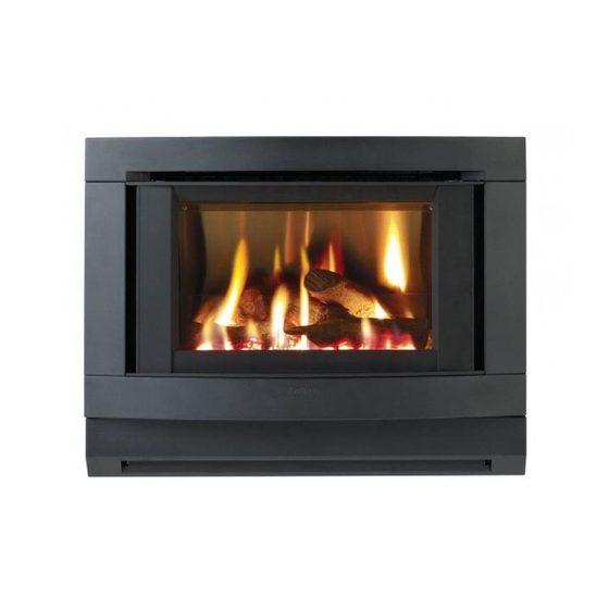
- Page 1 Cannon FITZROY INBUILT INBUILT MODELS FITZIB-SDSEB-NG FITZIB-SDSEB-LP USER INSTRUCTIONS INSTALLATION INSTRUCTIONS This heater is approved for use with Natural and Propane gases. SERVICE INSTRUCTIONS Please leave instructions with the owner...
-
Page 2: Table Of Contents
Contents Contents Warranty ❍ Distributor Safety warnings ❍ What to do if you smell gas ❍ Warnings ❍ Standards User instructions ❍ Operating instructions ❍ Cleaning ❍ Flame characteristics Heater specifications Installation instructions 10-14 ❍ Clearances ❍ Fitment of cabinet depth spacer ❍... -
Page 3: Warranty
Warranty The Cannon appliance is warranted against defects in materials and workmanship for a period of one, (1) year from its date of original pur- chase, for residential use in Australia. Warranty service, which includes parts and labour for the replacement or repair of defective parts, is available through the CANNON distributor. -
Page 4: Safety Warnings
Refer to other sections of this manual for correct procedures, or consult with place of purchase, a licensed plumber, a gas supplier or the CANNON distributor listed in this manual. 2. Do not build the heater into bookcases or walls. Install only on loca- tions as referred to on these installation instructions. -
Page 5: Standards
Before testing the flue confirm air vents are unobstructed. If an exhaust fan or other heating appliances are present switch them on. This is to test that there is no interaction between the Cannon heater and other appliances. Refer AS5601. -
Page 6: User Instructions
User instructions Operating instructions 1. Plug the power cord into the wall socket and turn on the power to the heater, see figure 1. Refrain from using an extension cord. 2. For control layout refer to figure 2 3. To turn heater on press switch to POWER ON position. There is a 5 second delay before the burner ignites. -
Page 7: Figure
5. To increase the fan speed to MED, press switch for MED setting. Refer figure 5. 6. To increase the fan speed to HIGH, press switch for HIGH setting. Refer figure 6. 7. To turn the burner to LOW setting, press switch for LOW setting. Refer figure 7. -
Page 8: Cleaning
Cleaning All cleaning should be carried out when the heater is cold. Normally the heater should only need wiping with a lint - free damp cloth. Any stubborn stains can be removed with a non-abrasive spray on cleaner. If an abrasive cleaner is used the paint finish will be damaged. -
Page 9: Heater Specifications
Heater specifications Gas type: Natural or Propane gas, as indicated Note: on data label The data label is located on the fan chamber base, Gas consumption: 26.0 MJ/hr rear of lower fascia. Energy output: 21.45 MJ/hr (5.96 KW) Energy star rating: 4 stars Heater type: Approved to AS 4553:2008. -
Page 10: Installation Instructions
Installation into a masonry/brick or mock fireplace. 5. Models FITZIB-SDSEB-NG & FITZIB-SDSEB-LP can be installed into a masonry/brick fireplace or a mock fireplace. If installing into a mock fireplace a mock fireplace installation kit MUST be used. The mock fireplace kit can be ordered from the CANNON distributor. -
Page 11: Installation With A Flue Connected
If an exhaust fan or other heating appliances are present switch them on. This is to test that there is no interaction between the Cannon heater and other appliances. -
Page 12: Installation Without A Flue Connected
Installation WITHOUT a flue connected... - Page 13 6. Prepare electrical and gas connections. A 10 Amp wall socket needs to be located within 1.5m of the heater. If using a power point in the chimney, route the plug and cord through cord access at lower LH side of rear panel. A grommet is fitted over the cord.
- Page 14 you gently to partly disengage it from the body of the heater. After it has been disengaged gently lift it up vertically to completely disengage it from the body of the heater. Refer figure 19 & 20. 11. Remove the inner glass. Slacken off screws in top clamp and remove side clamps.
-
Page 15: Gas Connections
Gas connections 13. Slide heater into the fireplace ensuring that gas inlet pipe is fed through the hole at the rear bottom RHS of the heater. Refer figure 24 and gas connection figure 26. 14. With heater in position, flanges should be hard against masonry. Se- cure case flanges to the masonry. -
Page 16: Log Installation
Log installation 16. The burner is contained within the burner chamber. Refer figure 27. 17. Carefully unpack the log set. Logs are numbered as follows: No 1 - Left front log No 2 - Left back log No 3 - Right front log No 4 - Right back log Position the four individually numbered logs in the following order on the burner head as shown in figure 28-31. -
Page 17: Gas Control
Gas control 23. Gas control layout is as indicated in figure 32. Important: To achieve the correct Pressures for ‘Burner full on’ and ‘Burner low flame’ are factory visual flame effect: set, however if pressures need to be checked or adjusted follow the On Propane the gas procedures described below and on the next two pages. - Page 18 pressure to 0.75 kPa for Natural gas or 2.65 kPa for LPG. (Turn clock- wise to increase pressure and anticlockwise to decrease pressure). 26. Switch the heat button back to “Low Flame’ position as indicated in figure 36(a), retain spanner in position and using a screwdriver as per figure 36(b) adjust the central screw control to give a pressure reading of 0.3 kPa for Natural Gas and 1.1 kPa for LPG.
-
Page 19: Installation Tips
❍ Test the operation of the chimney before installing the new heater. ❍ Be careful! CANNON heaters are high efficiency products with low flue gas tem- peratures (typically 100°C) so if you are replacing an older type radi- ant heater with a much higher flue gas temperature (150°C or higher) make sure of the integrity of the fireplace and chimney before installing the new CANNON log fire. -
Page 20: Trouble-Shooting
Trouble-shooting - (Do not modify this appliance) To check the operation of the electronic (module) controller (Type 537 ABC) you will require a digital multimeter with the functions to measure AC/DC voltage, continuity, resistance and micro-amps. It is critical that the appliance is earthed and that the active and neutrals are not reversed. Item No Check Action... -
Page 21: Connections
Sparks, ignites on low flame • Check that the wall socket to the appliance has then extinguishes after 10 correct polarity. Do not use an extension cord. Check seconds. Continues to spark polarity in the electrical supply lead to appliance. during flame presence. -
Page 22: Service Instructions
Service Instructions - (Do not modify this appliance) General 1. Service work to be carried out by an authorised service person only. 2. Unplug from wall socket or turn off power at main switchboard if heater is hard wired. 3. Always shut off the gas supply and ensure that the heater is cool before commencing any service operations. -
Page 23: To Replace The Fan Pressure Switch
the air intake slot. Refer page 13, figure 16, of the installation instructions. 2. Disconnect the fan plug from the plug carrier. Remove the two M5 wing nuts which locate the fan to the fan chamber underside. Lower fan from male thread. 3. -
Page 24: Wiring Diagram
Wiring diagram Data plate For service to this appliance For service to this appliance or spare parts contact the CANNON distributor. Sampford IXL Cannon 52 - 70 Sparks Avenue FITZROY INBUILT Fairfield, Vic, 3078 Phone: 1300 727 421 Fax: 1300 727 425...
Need help?
Do you have a question about the FITZIB-SDSEB-NG and is the answer not in the manual?
Questions and answers