Table of Contents

Related Manuals for Cannon FITZPIB


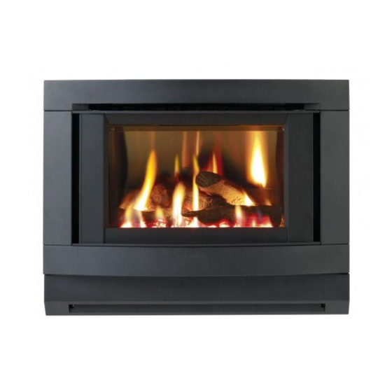
Summary of Contents for Cannon FITZPIB
- Page 1 MAKER’S WARRANTY Cannon FITZROY PROFILE INBUILT MODELS FITZPIB, FITZPIBLP USER INSTRUCTIONS INSTALLATION INSTRUCTIONS This heater is approved for use with Natural and Propane gases. SERVICE INSTRUCTIONS Please leave instructions with the owner...
-
Page 2: Table Of Contents
Contents Contents Warranty Safety warnings ❍ What to do if you smell gas ❍ Warnings ❍ Standards User instructions ❍ Operating instructions ❍ Cleaning Heater specifications Installation instructions 10-14 ❍ Clearances ❍ Fitment of cabinet depth spacer ❍ Installation into a masonry fire place ❍... -
Page 3: Warranty
Australia. Warranty service, which includes parts and labour for the replace- ment or repair of defective parts, is available through Cannon Authorised Service Agencies. (Please refer to the list of authorised service agents in this manual.) Consumers are responsible for service person’s travel outside nor-... -
Page 4: Safety Warnings
Safety Warnings Please read this manual before installing and using the heater. 1. Turn OFF the main gas supply. What to do if you smell 2. Extinguish any open flame. 3. Open windows. 4. Do not touch electrical switches. 5. Do not use your telephone. 6. -
Page 5: Standards
If removed the glass window must be put back onto the unit prior to operating the heater. 8. Installation and repairs should be performed by a licensed service person only, refer to back of brochure for service number. For installation into a non-combustible fireplace, i.e.: masonry or brick or into a mock fireplace, i.e. -
Page 6: User Instructions
User instructions Operating instructions 1. Plug the power cord into the wall socket and turn on the power to the heater, see figure 1. Refrain from using an extension cord. 2. For control layout refer to figure 2 3. To turn heater on press switch to POWER ON position. There is a 5 second delay before the burner ignites. - Page 7 5. To increase the fan speed to MED, press switch for MED set- ting. Refer figure 5. 6. To increase the fan speed to HIGH, press switch for HIGH setting. Refer figure 6. 7. To turn the burner to LOW setting, press switch for LOW set- ting.
-
Page 8: Cleaning
User instructions continued Cleaning. All cleaning should be carried out when the heater is cold. Nor- mally the heater should only need wiping with a lint - free damp cloth. Any stubborn stains can be removed with a non-abrasive spray on cleaner. If an abrasive cleaner is used the paint finish will be damaged. -
Page 9: Heater Specifications
Heater Specifications Do not use fire with broken or missing logs. Gas type: Natural or Propane gas, as indicated on data label Gas consumption: 26 MJ/hr input Energy star rating: 3.77 Energy output: 20.7 MJ/hr Heater type: Heater approved to AS 4553/AG103. -
Page 10: Installation Instructions
Installation instructions 1. This appliance is to be installed by a licensed service person only. 2. This appliance is to be installed in accordance with the manufacturer’s installation instructions, AS 5601/AG601, Mu- nicipal Building Codes, Electrical Wiring Regulations and any other statutory regulations. - Page 11 Assemble the spacer by fixing the two side sections to the top sections with a s/t screw (provided) each side. Refer figure 12. d. Fix spacer to front frame with 7 s/t screws (provided). Refer fig 13. e. Replace the front frame/spacer assembly by sliding the assembly down over the cabinet top flange and then push- ing it in firmly.
- Page 12 Installation instructions continued Installation into a 5. Models FITZPIB & FITZPIBLP can be installed into a masonry/ brick fireplace or a mock fireplace. If installing into a mock fireplace. fireplace a mock fireplace installation kit MUST be used. The mock fireplace kit can be ordered from the relevant service agent.
-
Page 13: Sealing
10.Disconnect the switch loom connector from the loom plug. Refer figure 20. 11. Remove the inner glass. Slacken off screws in top clamp and remove side clamps. Refer figure 21. Sealing 12. All gaps between heater case and fireplace are to be sealed. Seal with foam tape around top and sides of heater flange as required. - Page 14 Installation instructions continued 13. Slide heater into the fireplace ensuring that gas inlet pipe is fed through the hole at the rear bottom RHS of the heater. Refer figure 24 and gas connection figure 26. 14. With heater in position, flanges should be hard against ma- sonry.
-
Page 15: Gas Connection
Gas connections 15. Connect incoming gas supply pipe to regulator. For inlet posi- tion see figure 26. Close gate over gas supply and seal around the pipe with fibreglass insulation material. Sealing is impor- tant as it prevents leakage from fan chamber into chimney: also check for gas soundness. - Page 16 b) Place log No.2 onto the 2 left back pins. Refer figure 30. c) Place log No.3 on single right front pin, ensure fork locates over log No. 2, see figure 31. d) Place log No. 4 on single right back pin, ensure left side of log rests on depression in No.
-
Page 17: Gas Control
Gas control 23. Gas control layout is as indicated in figure 33. Pressures for ‘Burner full on’ and ‘Burner low flame’ are fac- tory set, however if pressures need to be checked or adjusted follow the procedures described below and on the next two pages. -
Page 18: Gas Pressure Adjustment
Gas pressure 25. Switch the top two control buttons to “Full On” position as indicated in figure 36(a) and using a ring spanner, as per adjustment figure 36(b), adjust the pressure to 1kPa for Natural gas or 2.65 kPa for LPG. (Turn clockwise to increase pressure and anticlockwise to decrease pressure). -
Page 19: Service Instructions
Service Instructions General 1. Service work to be carried out by a licensed service person only. 2. Unplug from wall socket or turn off power at main switchboard if heater is hard wired. 3. Always shut off the gas supply and ensure that the heater is cool before commencing any service operations. -
Page 20: Troubleshooting
Troubleshooting To check the operation of the electronic (module) controller (Type 537 ABC) you will require a digital multimeter with the functions to measure AC/DC voltage, continuity, resistance and micro-amps. It is critical that the appliance is earthed and that the active and neutrals are not reversed. Item No Check Action... -
Page 21: Connections
No gas to burner. • The gas valve should open at the same time as the igniter sparks. If there is no gas to the burner when this occurs check the solenoid coils for continuity. • Check that the gas pressure is present at the test point when the spark is being generated. -
Page 22: Authorised Service Agents
Wiring diagram Authorised service For further information or spare parts contact the CANNON dis- tributor in your state. agents Sampford & Staff Pty Ltd 421 Smith Street. Fitzroy, Vic, 3065 Vic/Tas: (03) 9418 5800 NSW: (02) 9331 8888 SA/NT: (08) 8212 7000... - Page 24 Cannon FITZROY PROFILE Part No: F2752 Revision B...
Need help?
Do you have a question about the FITZPIB and is the answer not in the manual?
Questions and answers
My Fitzroy has a round control knob with pilot setting. How do I turn heater on?
To turn on the Cannon Fitzroy heater with a round control knob and pilot setting, follow these steps:
1. Press the switch to the POWER ON position.
2. There is a 5-second delay before the burner ignites.
3. The heater will ignite with the burner on LOW and the fan speed on LOW.
4. The burner can operate on both HIGH and LOW settings.
Use the control knob to adjust between HIGH and LOW as needed.
This answer is automatically generated