Table of Contents

Related Manuals for Cannon FITZP


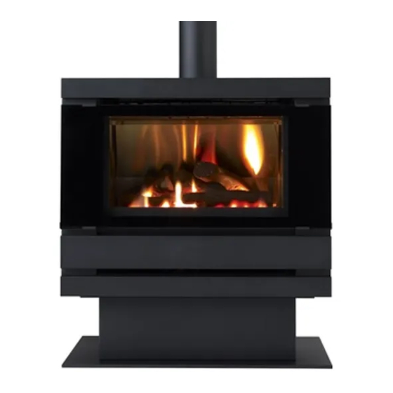
Summary of Contents for Cannon FITZP
- Page 1 Cannon MAKER’S WARRANTY FITZROY PROFILE FREESTANDING MODELS FITZP, FITZLP USER INSTRUCTIONS INSTALLATION INSTRUCTIONS This heater is approved for use with Natural and Propane gases. SERVICE INSTRUCTIONS Please leave instructions with the owner...
-
Page 2: Table Of Contents
Contents Contents Warranty Safety warnings ❍ What to do if you smell gas ❍ Warnings ❍ Standards User instructions ❍ Operating instructions ❍ Cleaning Heater specifications Installation instructions 10-15 ❍ Clearances ❍ Installation ❍ Gas connection ❍ Fuel bed & log installation ❍... -
Page 3: Warranty
Australia. Warranty service, which includes parts and labour for the replace- ment or repair of defective parts, is available through Cannon Authorised Service Agencies. (Please refer to the list of authorised service agents in this manual.) Consumers are responsible for service person’s travel outside nor-... -
Page 4: Safety Warnings
Safety Warnings Please read this manual before installing and using the heater. 1. Turn OFF the main gas supply. What to do if you smell 2. Extinguish any open flame. 3. Open windows. 4. Do not touch electrical switches. 5. Do not use your telephone. 6. -
Page 5: Standards
9. The appliance should be inspected prior to use, with regular inspections (annually) to be made by a licensed service per- son. It is important that circulating air passageways of the ap- pliance be kept clean, dirt and lint free, for a safe and efficient operation of the heater. -
Page 6: User Instructions
User instructions Operating instructions 1. Plug the power cord into the wall socket and turn on the power to the heater, see figure 1. Use of an extension cord is not recommended 2. For control lay-out refer to figure 2 3. - Page 7 5. To increase the fan speed to MED, press switch for MED set- ting. Refer figure 5. 6. To increase the fan speed to HIGH, press switch for HIGH setting. Refer figure 6. 7. To turn the burner to LOW setting, press switch for LOW set- ting.
-
Page 8: Cleaning
User instructions continued Cleaning. All cleaning should be carried out when the heater is cold. Nor- mally the heater should only need wiping with a lint - free damp cloth. Any stubborn stains can be removed with a non-abrasive spray on cleaner. If an abrasive cleaner is used the paint finish will be damaged. -
Page 9: Heater Specifications
Heater Specifications Gas type: Natural or Propane gas, as indicated on data label Gas consumption: 26 MJ/hr input Energy star rating: 3.77 Energy output: 20.7 MJ/hr Heater type: Heater approved to AG 103. Operating pressure: Natural gas: 1.0 kPa Propane gas: 2.65 kPa Min. -
Page 10: Installation Instructions
Installation Instructions 1. This appliance is to be installed by a licensed service person only. 2. This appliance is to be installed in accordance with the manufacturer’s installation instructions, AS 5601/AG 601, Municipal Building Codes, Electrical Wiring Regulations and any other statutory regulations. 3. - Page 11 9. Remove the heater front securing screws, one either side. Re- fer figure 12. 10.Remove the heater front by pulling it towards you gently to partly disengage it from the body of the heater then gently lift it up vertically to completely disengage it. Refer figure 13. 11.Remove the inner glass.
-
Page 12: Gas Connection
Installation instructions continued 12. Connect incoming gas supply pipe at gas control inlet. The Gas connection inlet fitting is located 150mm in from the rear pedestal wall RH side. Refer figure 15. 13. The fuel bed is contained within the burner chamber. Remove Fuel bed and log the fuel bed transit packaging. -
Page 13: Gas Control
b) Place log No.2 onto the 2 left back pins. Refer figure 18. c) Place log No.3 on single right front pin, ensure fork locates over log No. 2. Refer figure 19. d) Place log No. 4 on single right back pin, ensure left side of log rests on depression in No. -
Page 14: Gas Pressure Point
Installation instructions continued To check control outlet pressure at burner ‘Full on” and ‘Low Flame” positions remove the plastic cap from the regulator adjustment location as indicated in figures 22 (a) & (b). Gas pressure point 18 The pressure point is closed with a captive screw. Turn screw 6 revolution anticlockwise to open the pressure point as indi- cated on figure 23 (a) and place manometer tube over the test point as per figure 23 (b). - Page 15 27. Switch burners off and remove the manometer tube. Tighten pressure test point by turning the captive screw fully clockwise. Replace plastic cap. Ensure the little lug is positioned towards lower right hand side to clear the control. 28. Refit the lower front cover, making sure not to damage the power cord.
-
Page 16: Flue Installation
Flue installation This heater is a flued appliance. It must be properly connected to a flue system in accordance with the latest edition of the Gas Installa- tion Code, AS 5601/AG 601. If elbows are needed, the total horizontal length depends on the number of elbows used. -
Page 18: Service Instructions
Service Instructions General 1. Service work to be carried out by a licensed service person only. 2. Unplug from wall socket. 3. Always shut off the gas supply and ensure that the heater is cool before commencing any service operations. 4. -
Page 19: Wiring Diagram
Wiring diagram Authorised service agents For further information or spare parts contact the CANNON distributor in your state. Sampford & Staff Pty Ltd 421 Smith Street. Fitzroy, Vic, 3065 Vic/Tas: (03) 9418 5800 NSW: (02) 9331 8888 SA/NT: (08) 8212 7000... -
Page 20: Troubleshooting
Troubleshooting To check the operation of the electronic (module) controller (Type 537 ABC) you will require a digital multimeter with the functions to measure AC/DC voltage, continuity, resistance and micro-amps. It is critical that the appliance is earthed and that the active and neutrals are not reversed. Item No Check Action... -
Page 21: Connections
No gas to burner. • The gas valve should open at the same time as the igniter sparks. If there is no gas to the burner when this occurs check the solenoid coils for continuity. • Check that the gas pressure is present at the test point when the spark is being generated. -
Page 22: Notes
Notes... - Page 23 Notes...
- Page 24 Cannon FITZROY PROFILE Part No: F2774 Revision C...
Need help?
Do you have a question about the FITZP and is the answer not in the manual?
Questions and answers