Table of Contents
Advertisement
INSTALLATION NOTES
DON'T RISK YOUR APPLIANCE WARRANTY
ONLY A LICENSED PERSON WILL GIVE YOU A COMPIANCE
CERTIFICATE, SHOWING THAT THE WORK COMPLIES WITH
ALL THE RELEVANT STANDARDS.
AND ONLY A LICENSED PERSON WILL HAVE INSURANCE
PROTECTING THEIR WORKMANSHIP FOR 6 YEARS.
SO MAKE SURE YOU USE A LICENSED PERSON TO INSTALL
THIS APPLIANCE AND ASK FOR YOUR COMPLIANCE
CERTIFICATE TO ENSURE THE MANUFACTURERS
APPLIANCE WARRANTY WILL BE HONOURED.
Data label
Attach copy of data label here!
Date installed: ...............................................................................................
Installed by: ...................................................................................................
Compliance Certificate No .............................................................................
For service to this appliance or spare
parts contact the CANNON distributor:
Sampford IXL (spare parts)
Phone: 1300 727 421
Fax:
1300 727 425
email: service@sampfordixl.com.au
28
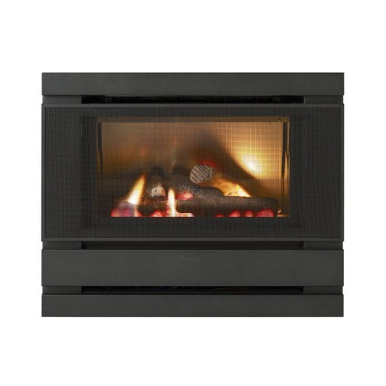
Cannon
FITZROY INBUILT
Part No: F2903
Revision K - 2010
Cannon
FITZROY INBUILT
INSTALLATION INSTRUCTIONS
USER INSTRUCTIONS
SERVICE INSTRUCTIONS
Gmk10025
AS4553:2008
PLEASE READ THIS MANUAL
BEFORE INSTALLING AND
USING THIS HEATER.
This heater is approved for use with
Natural and Propane gases.
Please leave instructions with the owner
Advertisement
Table of Contents

Related Manuals for Cannon Fitzroy Inbuilt


Summary of Contents for Cannon Fitzroy Inbuilt
- Page 1 Compliance Certificate No ................PLEASE READ THIS MANUAL BEFORE INSTALLING AND For service to this appliance or spare USING THIS HEATER. parts contact the CANNON distributor: Sampford IXL (spare parts) Cannon Phone: 1300 727 421 This heater is approved for use with...
-
Page 2: Table Of Contents
Contents NOTES Contents Warranty Distributor Heater specifications Safety warnings What to do if you smell gas Warnings Standards User instructions Operating instructions Cleaning Flame characteristics Installation instructions 9 -13 Clearances Fitment of cabinet depth spacer Installation into a masonry/brick or mock fireplace Installation WITH a flue connected Installation WITHOUT a flue connected Front fascia removal... -
Page 3: Warranty
Trade Practices Act and similar laws of the States and Territories. We warrant this Cannon appliance to be free of defects in materials, workmanship and manufacturing to the original purchaser for 2 years, (10 years on the heat exchanger) from the date of original purchase. -
Page 4: Heater Specifications
Heater specifications WIRING DIAGRAM Gas type: Natural or Propane gas, as indicated on data label Gas consumption: 26.0 MJ/hr Energy output: 5.98 kW Enery star rating: 4.05 stars Heater type: Gas space heater approved to AS 4553:2008 Operating pressure: Natural gas: 0.75 kPa (at burner high setting) Propane gas: 2.65kPa Gas regulator:... -
Page 5: Safety Warnings
2. Remove the burner chamber front inspection panel, 4 screws. or the CANNON distributor listed in this manual. 3. Disconnect the 16mm nut at the outlet of the gas control. -
Page 6: Standards
This is to test that there is are not kinked or pinched. no interaction between the Cannon heater and other appliances. 8. Reconnect fan plug into plug carrier. Test operation of room circulation fan and fan Refer to Australian Standard Gas Installations AS 5601. -
Page 7: User Instructions
User instructions Service Instructions - (Do not modify this appliance) General Operating instructions 1. Service work to be carried out by an authorised service person only. Plug the power cord into the wall socket and turn on the 2. Unplug from wall socket or turn off power at main switchboard if heater is hard wired. power to the heater (see figure 2). -
Page 8: Cleaning
Cleaning Check that the wall socket to the appliance has 8. Sparks, ignites on low flame All cleaning should be carried out when the heater is cold. Normally the correct polarity. Do not use an extension cord. then extinguishes after 10 heater should only need wiping with a lint-free damp cloth. -
Page 9: Installation Instructions
Check the continuity of the HT cable. produced. than 50mm a spacer kit must be fitted. The spacer can be ordered from the Cannon Check that there is no short circuit to earth and spark distributor. gap is correct. A positive check is to use a jumper Order specification for the spacer is ‘BSPACERX-B’... -
Page 10: Cleaning
Test the operation of the chimney before installing the new heater. interaction between the Cannon heater and other appliances. Be careful! CANNON heaters are high efficiency products with low flue gas temperatures (typically 100°C) so if you are replacing an older type Refer to Australian Standard Gas Installations AS 5601: radiant heater with a much higher flue gas temperature (150°C or higher) -
Page 11: Installation Without A Flue Connected
3. Switch the control buttons to ‘High flame’ position as indicated in figure 27 Installation WITHOUT a flue connected and using a spanner adjust the pressure to 0.75 kPa for Natural gas or 2.65 kPa for LPG. (Turn clockwise to increase pressure and anticlockwise to decrease pressure). -
Page 12: Front Fascia Removal
Front Fascia removal Gas control 1. Remove the wire mesh grille by gently lifting it upwards and then outwards. 1. Gas control layout is as indicated in figure 24. Similarly remove a fitted glass kit by also gently lifting it upwards and then outwards. -
Page 13: Sealing The Fascia
Sealing the Fascia Gas connections 1. Push the gas inlet access plate into the heater cabinet and slide the heater into the fireplace ensuring that the gas inlet pipe is fed through the hole located at the rear All gaps between heater case and fireplace are right hand side of the heater at the bottom. -
Page 14: Log Installation
Electrical Connection Log installation This appliance is designed to operate on 240V AC power supply. Failure to 1. The burner is contained within the burner operate unit at correct supply voltage may created unsafe conditions. chamber. Refer figure 15. 2. Carefully unpack the log set. Logs are numbered as follows: #1 - Left front log #2 - Left back log...
Need help?
Do you have a question about the Fitzroy Inbuilt and is the answer not in the manual?
Questions and answers