Table of Contents
Advertisement
Quick Links
INSTALLATION NOTES
DON'T RISK YOUR APPLIANCE WARRANTY
ONLY A LICENSED PERSON WILL GIVE YOU A COMPIANCE
CERTIFICATE, SHOWING THAT THE WORK COMPLIES WITH
ALL THE RELEVANT STANDARDS.
AND ONLY A LICENSED PERSON WILL HAVE INSURANCE
PROTECTING THEIR WORKMANSHIP FOR 6 YEARS.
SO MAKE SURE YOU USE A LICENSED PERSON TO INSTALL
THIS APPLIANCE AND ASK FOR YOUR COMPLIANCE
CERTIFICATE TO ENSURE THE MANUFACTURERS
APPLIANCE WARRANTY WILL BE HONOURED.
COPY RATING LABEL HERE
Date installed: ...............................................................................................
Installed by: ...................................................................................................
Compliance Certificate No .............................................................................
For service to this appliance or spare
parts contact the CANNON distributor:
Sampford IXL (spare parts)
Phone: 1300 727 421
Fax:
1300 727 425
email: service@sampfordixl.com.au
28
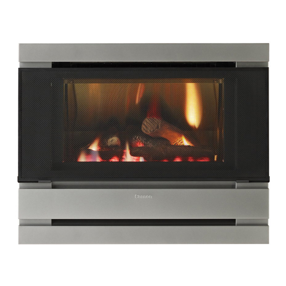
Cannon
FITZROY INBUILT
Power Flue
Part No: F3045
Revision P - 2010
Cannon
FITZROY INBUILT
OPERATION INSTRUCTIONS
INSTALLATION INSTRUCTIONS
SERVICE INSTRUCTIONS
Gmk10030
AS4553:2008
Power Flue
PLEASE READ THIS MANUAL
BEFORE INSTALLING
THIS HEATER.
This heater is approved for use with
Natural and Propane gases.
Please leave instructions with the owner
Advertisement
Table of Contents

Related Manuals for Cannon Fitzroy Powerflue In-built


Summary of Contents for Cannon Fitzroy Powerflue In-built
- Page 1 Date installed: ....................Installed by: ....................Compliance Certificate No ................PLEASE READ THIS MANUAL BEFORE INSTALLING For service to this appliance or spare parts contact the CANNON distributor: THIS HEATER. Cannon Sampford IXL (spare parts) Phone: 1300 727 421 FITZROY INBUILT...
-
Page 2: Table Of Contents
CONTENTS NOTES Contents Warranty ? Distributor Heater specifications Safety warnings ? What to do if you smell gas ? Warnings Standards Regulatory location User instructions ? Operating instructions ? Cleaning ? Flame characteristics Installation instructions 10 -13 ? Clearances ? Fitment of cabinet depth spacer ? Flueing options ? Fitment of flue cowl ? Preparing flexible flue pipes... -
Page 3: Warranty
Trade Practices Act and similar laws of the States and Territories. We warrant this Cannon appliance to be free of defects in materials, workmanship and manufacturing to the original purchaser for 2 years, (10 years on the heat exchanger) from the date of original purchase. -
Page 4: Heater Specifications
WIRING DIAGRAM HEATER SPECIFICATIONS Gas type:Natural or Propane gas, as indicated on data label Gas consumption: 26.0 MJ/hr Energy output: 5.98 kW Enery star rating: 5.05 stars Heater type: Gas space heater approved to AS 4553:2008 Operating pressure: Natural gas: 0.75 kPa (at burner high setting) Propane gas: 2.65kPa Gas regulator:... -
Page 5: Safety Warnings
CANNON distributor listed in this manual. and carefully remove from the burner chamber. 10. Pull electrode leads from the gland seal. -
Page 6: Standards
This is to test that there is wiring. Take care to ensure that silicon tubes are on the correct no interaction between the Cannon heater and other appliances. spigots on the pressure switch. -
Page 7: Regulatory Location
REGULATORY LOCATION SERVICE INSTRUCTIONS - (DO NOT MODIFY THIS APPLIANCE) General 1. Service work to be carried out by an authorised service person only. FIG 2. MINIMUM CLEARANCES REQUIRED FOR BALANCED FLUE 2. Unplug from wall socket or turn off power at main switchboard if heater TERMINALS, FAN ASSISTED FLUE TERMINALS, ROOM SEALED APPLIANCE is hard wired. -
Page 8: Troubleshooting
TROUBLESHOOTING USER INSTRUCTIONS Operating instructions FIG 3. Confirm spark is produced A blue spark can be seen when the heater ignition process when heater is turned on. starts. Ensure spark is present between electrode and burner. Plug the power cord into the wall socket and turn on the power to the heater (see figure 3). -
Page 9: Cleaning
TROUBLESHOOTING-(DO NOT MODIFY THIS APPLIANCE) CLEANING All cleaning should be carried out when the heater is cold. Normally the To check the operation of the electronic (module) controller (Techrite) heater should only need wiping with a lint-free damp cloth. Any stubborn you will require a digital multimeter with the functions to measure ac / dc stains can be removed with a non-abrasive spray on cleaner. -
Page 10: Clearances
INSTALLATION DETAIL INSTALLATION DETAIL 3. Switch the control buttons to ‘High flame’ position as indicated in figure 26 1. This appliance is to be installed by an authorised service person only. and using a screwdriver held in position adjust spanner to the pressure 2. -
Page 11: Flueing Options
GAS CONTROL FLUEING OPTIONS 23. Gas control layout is as indicated in figure 23. The heater is supplied with components to suit a horizontal flue coming through a wall at the back of the heater. The Components include a flue cowl Pressures for ‘Burner full on’... - Page 12 INSTALLATION DETAIL INSTALLATION DETAIL CAVITY REQUIREMENTS PVC VENT The heater is to be fitted into position with the flue pipes fully installed onto the TERMINAL INSTALLATION heater. Therefore, the cavity must be prepared to accept the heater first. PVC PIPE Before cutting any flue opening in the external wall, the finished floor level must PVC ADAPTOR FLUE TERMINAL...
- Page 13 INSTALLATION DETAIL INSTALLATION DETAIL Position sealing tape around perimeter of 695 mm INSTALLING HEATER heater rear edge behind mounting face. See fig 17. SEALING TAPE 160 DIA FLUE OPENING APPLIED TO EDGE OF UNIT BEFORE POSITIONING. Bend gas pipe and electrical entry tags inwards to allow cable and gas pipe to enter 20 DIA CONDENSE DRAIN HOLE easily.
-
Page 14: Log Installation
LOG INSTALLATION FRONT FASCIA REMOVAL 1. Remove the wire mesh grille by gently lifting it upwards and then outwards. Similarly remove a fitted glass kit by also gently lifting it upwards and then Carefully unpack the log set. Logs are numbered outwards.
Need help?
Do you have a question about the Fitzroy Powerflue In-built and is the answer not in the manual?
Questions and answers