Table of Contents
Advertisement
Quick Links
Advertisement
Table of Contents

Related Manuals for Cannon FITZFS-SDSEB-NG


Summary of Contents for Cannon FITZFS-SDSEB-NG
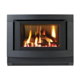
- Page 1 Cannon FITZROY FREESTANDING FREESTANDING MODELS FITZFS-SDSEB-NG FITZFS-SDSEB-LP USER INSTRUCTIONS INSTALLATION INSTRUCTIONS This heater is approved for use with Natural and Propane gases. SERVICE INSTRUCTIONS Please leave instructions with the owner...
-
Page 2: Table Of Contents
Contents Contents ❍ Distributor Warranty Safety warnings ❍ What to do if you smell gas ❍ Warnings ❍ Standards User instructions ❍ Operating instructions ❍ Flame characteristics ❍ Cleaning Heater specifications Installation instructions 10-15 ❍ Clearances ❍ Installation ❍ Gas connection ❍... -
Page 3: Distributor
Warranty The Cannon appliance is warranted against defects in materials and work- manship for a period of one, (1) year from its date of original purchase, for residential use in Australia. Warranty service, which includes parts and labour for the replacement or repair of defective parts, is available through the CANNON distributor. -
Page 4: Safety Warnings
Refer to other sections of this manual for correct procedures, or consult with place of purchase, a licensed plumber, a gas supplier or the CANNON distributor listed in this manual. 2. Do not build the heater into bookcases or walls. Install only as referred to in these installation instructions. -
Page 5: Standards
Before testing the flue confirm air vents are unobstructed. If an exhaust fan or other heating appliances are present switch them on. This is to test that there is no interaction between the CANNON heater and other appliances. Refer AS5601. -
Page 6: User Instructions
User instructions Operating instructions 1. Plug the power cord into the wall socket and turn on the power to the heater, see figure 1. Use of an extension cord is not recommended. 2. For control lay-out refer to figure 2. 3. - Page 7 5. To increase the fan speed to MED, press switch for MED setting. Refer figure 5. 6. To increase the fan speed to HIGH, press switch for HIGH setting. Refer figure 6. 7. To turn the burner to LOW setting, press switch for LOW setting. Refer figure 7.
-
Page 8: Flame Characteristics
Flame characteristics The heater flames should be stable, not lifting from burner and the logs should glow after approximately 15 minutes operation on HIGH setting. The heater has been designed to burn with luminous flames, which mimic natural log combustion, and may exhibit slight carbon deposition. If heavy carbon deposits occurs or flames impinge on the roof of the combustion chamber, turn the appliance off and contact the service agent in your state. -
Page 9: Heater Specifications
Heater specifications Gas type: Natural or Propane gas, as indicated Note: on data label The data plate is located on the rear Gas consumption: 26 MJ/hr input of the removable Energy output: 21.45 MJ/hr (5.96 KW) pedestal front. Energy star rating: 4 stars Heater type: Approved to AS4553:2008... -
Page 10: Installation Instructions
Installation instructions 1. This appliance is to be installed by a licensed service person only. 2. This appliance shall be installed in accordance with the manufacturer’s installation instructions, local gas fitting regulations, municipal building codes, electrical wiring regulations, and AS5601 the Australian Stand- ard for gas installations. - Page 11 8. Remove the pedestal front by unscrewing two screws either side. Re- fer figure 11. 9. Remove the heater front securing screws, one either side. Refer figure 10.Remove the heater front by pulling it towards you gently to partly disengage it from the body of the heater then gently lift it up vertically to completely disengage it.
-
Page 12: Gas Connection
Gas connection 12. Connect incoming gas supply pipe to ” compression fitting at rear of appliance. For inlet position see figure 15. Log installation 13. The burner is contained within the burner cham- ber. .Refer figure 16. 14. Carefully unpack the log set. Logs are numbered as follows: No 1 - Left front log No 2 - Left back log No 3 - Right front log... -
Page 13: Gas Control
Advise the user in the d) Place log No. 4 on single right back operation of the heater. pin, ensure left side of log rests on de- pression in No. 3 log. Refer figure 20. 15. Refit the inner glass, but do not overtighten the screws. -
Page 14: Gas Pressure Point
Gas pressure point 18 The pressure point is closed with a captive screw. Turn screw 6 revolu- tions anticlockwise to open the pressure point as indicated on figure 23 (a) and place manometer tube over the test point as per figure 23 (b). -
Page 15: Installation Tips
23. Follow User Instructions to turn on heater and test for correct operation before leaving. 24.The heater flames should be stable, not lifting from burner and the logs should glow after approximately 15 minutes operation on HIGH set- ting. The heater has been designed to burn with luminous flames, which mimic natural log combustion, and may exhibit slight carbon deposits. -
Page 16: Flue Installation
Flue installation This heater is a flued appliance. It must be properly connected to a flue system in accordance with the latest edition of the Gas Installation Code, AS 5601. If elbows are required, we recommend 45° only and no more than two in the total flue run. -
Page 18: Service Instructions
Service instructions. (Do not modify this appliance). General 1. Service work to be carried out by an authorised service person only. 2. Unplug from wall socket or turn off power at main switchboard if heater is hard wired. 3. Always shut off the gas supply and ensure that the heater is cool before commencing any service operations. -
Page 19: To Replace The Fan Pressure Switch
page 11, figures 11 and 12, of the installation instructions. 2. Disconnect the fan plug from the plug carrier. Remove the two M5 wing nuts which locate the fan to the fan chamber underside. Lower fan from male thread. 3. Disconnect the silicon tube from the fan pressure switch, rotate the fan scroll 90°... -
Page 20: Wiring Diagram
Wiring diagram Data label For service to this appliance For service to this appliance or spare parts contact the CANNON distributor: Sampford IXL 52-70 Sparks Avenue Fairfield, Vic, 3078 Phone: 1300 727 421 Fax: 1300 727 425 email: service @ sampfordixl.com.au... -
Page 21: Trouble Shooting
Trouble-shooting. (Do not modify this appliance). To check the operation of the electronic (module) controller (Type 537 ABC) you will require a digital multimeter with the functions to measure AC/DC voltage, continuity, resistance and micro-amps. It is critical that the appliance is earthed and that the active and neutrals are not reversed. Item No Check Action... - Page 22 No gas to burner. • The gas valve should open at the same time as the igniter sparks. If there is no gas to the burner when this occurs check the solenoid coils for continuity. • Check that the gas pressure is present at the test point when the spark is being generated.
- Page 24 Cannon Part No: F2904 FITZROY FREESTANDING Revision D-2009...
Need help?
Do you have a question about the FITZFS-SDSEB-NG and is the answer not in the manual?
Questions and answers