Falcon SSG1.5KRM-1 Owner's Operating Manual
Ssg series rackmount industrial-grade ups plus
Hide thumbs
Also See for SSG1.5KRM-1:
- Installation & user manual (48 pages) ,
- Installation & user manual (48 pages)
Table of Contents
Advertisement
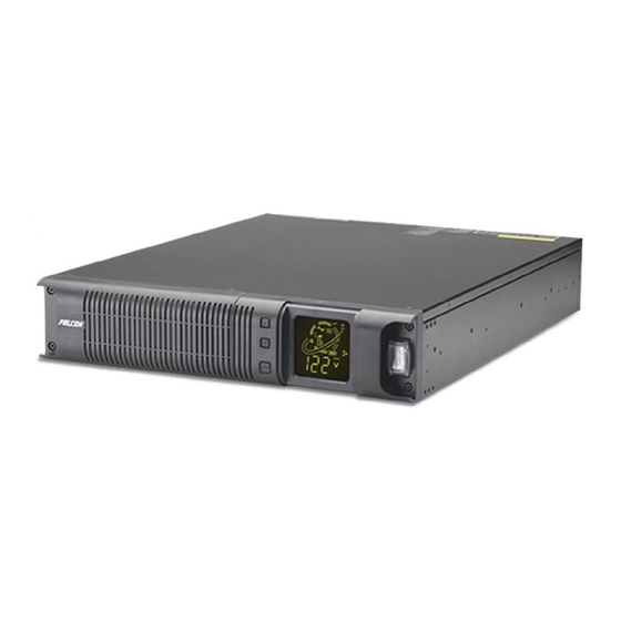
SSG1.5KRM-1 - 1.5kVA, 1050W, 120Vac, -20ºC - 55ºC (-4ºF to 131ºF) Operation
SSG1.5KRM-2 - 1.5kVA, 1050W, 230Vac, -20ºC - 55ºC (-4ºF to 131ºF) Operation
SSG2.2KRM-1 2.2kVA, 1540W, 120Vac, -20ºC - 55ºC (-4ºF to 131ºF) Operation
SSG2.2KRM-HW 2.2kVA, 1540W, 120Vac, -20ºC - 40ºC (-4ºF to 104ºF) Operation
SSG2.2KRM-2 - 2.2kVA, 1540W, 230Vac, -20ºC - 55ºC (-4ºF to 131ºF) Operation
SSG3KRM-1 3kVA, 2100W, 120Vac, -20ºC - 55ºC (-4ºF to 131ºF) Operation
SSG3KRM-HW 3kVA, 2100W, 120Vac, -20ºC - 40ºC (-4ºF to 104ºF) Operation
SSG3KRM-2 - 3kVA, 2100W, 230Vac, -20ºC - 55ºC (-4ºF to 131ºF) Operation
FALCON
®
Electric Inc., 5116 Azusa Canyon Rd., Irwindale, California 91706, 626.962.7770, Fax 626.962.7720, Email: sales@falconups.com
2012 Falcon
®
Electric Inc. All rights reserved.
All other brand names and trademarks are the property of their respective owners.
The information stated in this document is subject to change without notice. 2012-24--1
®
Falcon
, Falcon® Electric and UPS Plus logos are registered trademarks of Falcon Electric, Inc.
OPERATING
SSG Series
TM
Rackmount Industrial-Grade UPS Plus
Uninterruptible Power Supply Models:
SSG Rackmount Models
OWNER'S
MANUAL
®
Advertisement
Table of Contents

Related Manuals for Falcon SSG1.5KRM-1


Summary of Contents for Falcon SSG1.5KRM-1
- Page 1 All other brand names and trademarks are the property of their respective owners. The information stated in this document is subject to change without notice. 2012-24--1 ® Falcon , Falcon® Electric and UPS Plus logos are registered trademarks of Falcon Electric, Inc.
-
Page 2: Table Of Contents
Setting the UPS output voltage. Setting the load segment options. Chapter 7. Communications RS-232 & USB REPO SSG1.5KRM-1 rear panel layout SSG2.2KRM-1 & SSG3KRM-1 rear panel layout.. SSG2.2KRM-HW & SSG3KRM-HW rear panel layout & wiring. Chapter 8. Maintenance Storing the UPS When to replace batteries SSG1.5KRM-X Internal Battery Replacement... -
Page 3: Ssg Ups Features
SSG Series Industrial-Grade UPS Features True Double Conversion On-Line Sinewave Design High Temperature 55 C Operation LCD Display with Advanced Monitoring Output Load Segment Control Remote Emergency Power Off (REPO) Input Power Factor Correction Wide Input Voltage Window Precision Output Voltage Regulation Superior Brownout, Surge and Transient Protection Optional Frequency Converter Operation User Replaceable and Hot Swappable Battery Pack... -
Page 4: Important Safety Instructions (Read First)
IMPORTANT SAFETY INSTRUCTIONS, SAVE THESE INSTRUCTIONS RETAIN THIS USER MANUAL! This manual contains important instructions which must be followed during the installation, operation and maintenance of the SSG Series UPS, battery banks, options and batteries. Please read all instructions before operating this equipment and save this manual for future reference. All of the models presented herein are designed for installation and use in a temperature controlled environment, free of contamination. -
Page 5: Chapter 1. Introduction
1.0 INTRODUCTION Manual Overview This user manual has been written to provide basic information about the Falcon SSG Series Industrial Grade UPS Plus. SSG models are available in nominal power ratings of 1500, 2200 and 3000 VA . The SSG Series is a compact, rugged, double conversion, "on-line" UPS. It provides continuous power conditioning and accepts a wide range input voltage while providing tight output voltage regulation with a true sinewave output. -
Page 6: Chapter 2. Ssg Ups Circuit Descriptions Input Filter
-20º C - 55º C (-4º F to 131º F), at these temperatures, battery life will be substantially reduced. Optional extended battery modules are available through Falcon and will extend the amount of battery runtime. Please refer to the exact UPS model in the attached specificaitons for the specific battery option part number. - Page 7 Lithium-Ion-Phosphate batteries must be recycled - never dispose of the batteries in a land-fill or trash. Caution: Should a model SSG1.5KRM-1-LI or SSG1.5KRM-2-LI UPS require shipment by air transporation the shipping instrucitons on the following page must be followed:...
- Page 8 Never Apply a Short Circuit Across The Batteries as Personnel Injury, Fire or Explosion May Result. DANGER ---- NEVER ATTEMPT TO CONNECT AN EXTENDED BATTERY BANK CONTAINING VRLA LEAD-ACID BATTERIES TO A UPS CONTAINING INTERNAL LITHIUM-ION-PHOSPHATE BATTERIES.
-
Page 9: Manual Bypass Function
SSG3KRM-X 1 battery module 2 boxes shipped If you have not received the proper number of boxes, please contact Falcon Electric Customer Service at 1-800-842-6940. This UPS is shipped complete with all cables required for operation, including UPSILON software, and rackmount ears for 19" rackmount shelf mounting. A full list of the box contents is provided as follows: SSG1.5KRM-X... -
Page 10: Inspecting The Equipment
To file a claim for shipping damage or concealed damage: YOU MUST file with the carrier within 15 days of receipt of the equipment; YOU MUST send a copy of the damage claim within 15 days to Falcon Electric, Inc. CAUTION The UPS and Battery Module are heavy. - Page 11 ** Securing hardware, slide rails and rail extensions are sold separately. Contact Falcon Electric for these additional options and any assistance needed.** Attach the two mounting brackets to the rack's mounting rails. The brackets allow adjustment of up to eight inches of the slide assembly mounting position, front-to-back, on the rack-mounting rails.
-
Page 12: Free Standing Tower Installation With Optional Mounting Feet
Free-standing (tower) Installation (mounting feet to be purchased seperately) When installing the SSG Series UPS in a free-standing configuration, mounting feet for the SSG1.5KRM-1 model may be purchased seperately to stableize the UPS provided with mounting feet (shown below, left) to stabilize the UPS. The SSG2.2KRM-1 and SSG3KRM-1 models are provided with keyhole hardware to "lock"... -
Page 13: Lcd Display Repositioning
Additional battery banks can be connected to the UPS to provide additional battery run time. There are two models of extended battery banks available for the SSG Series. Falcon model number SSGR is a universal battery bank without an internal charger. It may be added to any SSG 1.5-3kVA models. -
Page 14: Extended Battery Bank Information
SSG Extended Battery Bank Information EXTENDED BATTERY BANK (EBM) Number BACKUP EXTENDED BATTERY BANK (EBM) OPTIONS OPTIONS of parallel TIME (1) (With Internal Battery Charger) battery BATTERY Extended # Of Recharge Extended # Of Recharge Charger Charger Recharge Weight UPS Model Battery strings (Models... -
Page 15: Battery Bank Installation Procedure
The battery modules have been designed to be placed on one side of the UPS as shown below. Visually inspect the battery module for any freight damage. Report damage to the carrier and Falcon Electric immediately. Use the mounting feet to secure the unit and to prevent them from tipping over. One additional set of mounting feet base extensions ships with each battery bank. -
Page 16: Chapter 4. Displays & Controls Lcd & Led Indicators & Icons
4.0 DISPLAY & CONTROLS The diagram below shows the basic functions of the front panel for all SSG Series 1.5-3kVA UPS models. Indicators and Icons located on the LCD models LED display: Green Mode: The bulb icon is displayed continuously when the Green Mode function is enabled. -
Page 17: Function/Test Button
Controls (all models): The primary front panel user controls consist of one input circuit breaker and three push-buttons: The switch located to the right of display is the main input circuit breaker and controls the connection of utility power to the UPS and its internal battery charger. The three buttons located to the left of the LCD display are for primary manual control and program- ming of the UPS. -
Page 18: Chapter 5. Ups Operation
CAUTION When the UPS is in Normal On-line mode, pressing the bypass button once will put the UPS into Bypass Mode. While in bypass, should the utility power become unavailable, the UPS output will turn off and the UPS will shut down. Once the unit is in Bypass Mode operation, pressing this button again will force UPS back to on-line mode operation. -
Page 19: Bypass Mode
BYPASS MODE OPERATION The UPS will automatically transfer to Bypass Mode in the event it is overloaded, experiences an internal failure and for the conditions listed below. When in bypass, the UPS will transfer the con- nected load directly to the incoming utility power. When in bypass mode, Battery Mode will not be available. -
Page 20: Chapter 6. Ups Setup, Configuration & Programming
NOTE! DURING SHUT DOWN, DO NOT PRESS ANY BUTTON SINCE UPS MIGHT BE RE-ENERGIZED AND DELIVER POWER TO ITS OUTPUT UNEXPECTEDLY. 6.0 UPS SETUP, CONFIGURATION & PROGRAMMING The following section describes how to reconfigure the internal UPS setup options, by using the Setup, Configuration &... -
Page 21: Setting The Ups Output Voltage
Green Mode Setup How to Enable or Disable Green Mode (Function Bit 2) To Enable: 1. Press the "Function/Test" and “Set/Alarm Silence" buttons at same time and hold them for one second. The unit will sound one beep and then enter the Configuration Mode. -
Page 22: Setting The Load Segment Options
Output Voltage Select Setup Example - How to Set the UPS Output Voltage to 115Vac (-1 models) or 230Vac (-2 Models) 1. Press the "Function/Test" and "Set/Alarm Silence" buttons at same time and hold them for one second. The unit will emit one alarm beep and then enter the Configuration Mode. - Page 23 Making Load Segment Settings A. Setting load segments to automatically turn off the load segment when utility power is lost 1. Press the "Function/Test" and "Set/Alarm Silence" buttons at same time and hold them for one second. The unit will emit one alarm beep and then enter the Configuration Mode.
-
Page 24: Chapter 7. Communications
UPSilon software CD. The UPSilon users manual is also located on the UPSilon CD supplied with this unit. UPSilon supports most popular operating systems. Should you have special UNIX requirements, please contact Falcon Sales for information and pricing of UPSilon for UNIX. -
Page 25: Repo
The supplied Falcon RS-232 interface cable pin designations are as follows: The computer RS-232 Port settings should be set to the following: Remote Emergency Power Off (REPO) A two-pin REPO connector is located on the rear panel of the UPS. The connector is shipped with a jumper wire installed, to facilitate the normal operation of the UPS in the event an REPO connection is not used. -
Page 26: Ssg2.2Krm-1 & Ssg3Krm-1 Rear Panel Layout
SSG2.2KRM-1 & SSG3KRM-1 Rear Panel Layout Contact Closure Interface Card Option (New UA88374-SSG) Replaces UA88374 Note: This card installs into the Communicaitons Option Slot JUMPER SETTINGS DB-9 PIN ASSIGNMENTS J1 through J7 = 1-2 DB-9 configured for Green cable (Default) J1 through J7 = 2-3 DB-9 configured for standard RS-232 cable 1 = Not Used Note: J1-J7 must be all configured 1-2 or 2-3, or UPS and PC may be damaged. -
Page 27: Ssg2.2Krm-Hw & Ssg3Krm-Hw Rear Panel Layout & Wiring
SSG2.2KRM-HW & SSG3KRM-HW Rear Panel Layout OUTPUT WIRING DETAILS Line Neutral Neutral Line... -
Page 28: Chapter 8. Maintenance
"Function/Test" button and conducting a battery test. If the UPS goes back to normal On-line Mode in less than 10 seconds with one long beep, the batteries need replacing. Contact Falcon Electric Service Department to order replacement battery packs. 4. Battery Pack Replacement With the hot-swappable battery pack feature, the SSG Series UPS battery pack is easily replaced, without having to turn the UPS off or disconnecting the load. -
Page 29: Ssg1.5Krm-X Internal Battery Replacement
Unpack the new battery pack. Take care not to destroy the packaging. Compare new and old battery packs and verify that they are the same type. If so, proceed with the next step, otherwise stop and contact Falcon Service. Line up and slide in the new replacement battery pack in the correct orientation, by referring to the mark on the original battery pack. -
Page 30: Ssg2.2Krm-X, Ssg3Krm-X, Ssgr & Ssgr-X Battery Replacement
If a single, long audible tone is sounded and the unit does not switch to Battery Mode, this indicates that either the batteries are defective, installed incorrectly, the battery pack is not installed, the battery bank interconnect cable is not installed, or the battery fuse is missing or defective. If the problem cannot be resolved, contact Falcon Service. - Page 31 “on” position. If the problem cannot be resolved, contact Falcon Service.
-
Page 32: Recycling Used Battery Packs
The entire spent battery packs may be returned to the Falcon Service Center at the end user’s expense for recycling. Prior to returning the spent battery pack(s), please call the Falcon Service Center and obtain a Return Materials Authorization (RMA) number. -
Page 33: Chapter 9. Troubleshooting
9.0 TROUBLESHOOTING Audible Alarms The SSG Series UPS features audible alarm codes to alert the user of potential problems. Please refer to the following table to identify and resolve alarms and the conditions causing the alarms. - Page 34 Upon the UPS sounding a continious alarm condition, the alarm status bit will be displayed on the LCD display located on the UPS front panel. Please note the status bit number displayed and con- tact the Falcon service department immedately. To assist please inform them of the bit(s) displayed. BIT 0 ;DC BUS voltage over high flag BIT 1 ;soft start fault flag...
- Page 35 Prior to attempting any troubleshooting, always verify the UPS battery fuse is installed and the input voltage, input plug and wiring are correct. Please refer to the table below and attempt to solve the problem prior to contacting Falcon Service.
- Page 36 FCC Considerations Note: This equipment has been tested and found to comply with the limits for a Class B digital device, pursuant to part 15 of the FCC Rules. These limits are designed to provide reasonable protection against harmful interference in a residential installation.
-
Page 37: Chapter 10. Technical Support
You may request technical information or support by email or telephone. Please send your technical or support questions by email to: SUPPORT@FALCONUPS.COM You may contact a FALCON support engineer directly by calling the FALCON support line between 9:00 am and 4:00 pm PST. 800.842.6940 FALCON Web Support... -
Page 38: Warranty
Falcon with an RMA number. For defective product returned within 30 days of shipment, Falcon will pay for shipping costs to and from its service center. For defective product returned after 30 days but within 90 days of shipment, Falcon will only pay for shipping costs in sending the new or repaired product back to the end-user. -
Page 39: Specifications
All other brand names and trademarks are the property of their respective owners. The information and specifications stated in this document are subject to change without notice. 08-13-2010 Falcon Electric, Inc. - 5106 Azusa Canyon Rd. - Irwindale, CA 91706 - 800.842.6940 Fax 626.962.7720 www.falconups.com - email: sales@falconups.com... - Page 40 Falcon Electric logo are registered trademarks of Falcon Electric, Inc. All other brand names and trademarks are the property of their respective owners. Falcon Electric, Inc. - 5116 Azusa Canyon Rd. - Irwindale, CA 91706 - 800.842.6940 Fax 626.962.7720 www.falconups.com - email: sales@falconups.com...
Need help?
Do you have a question about the SSG1.5KRM-1 and is the answer not in the manual?
Questions and answers