Table of Contents
Advertisement
Quick Links
Advertisement
Table of Contents

Related Manuals for Falcon SUP700-1C


Summary of Contents for Falcon SUP700-1C
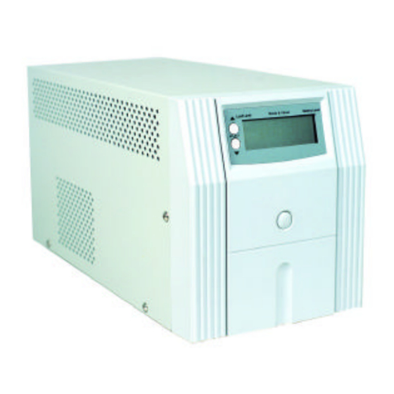
- Page 1 FALCON ELECTRIC, INC. ® SUP Series User’s Guide 700-1000VA SUP700-1C, SUP1.0K-1C FALCON® ELECTRIC, INC. 5116 Azusa Canyon Road Irwindale, CA 91706 Tel. 626-962-7770 Fax. 626 962-7720 WWW.FALCONUPS.COM 800.842.6940 OM48031-SUP, 01/09/04, Rev A.
-
Page 2: Table Of Contents
Remote Control Chapter 5. Maintenance & Technical Support Care & Maintenance Battery Replacement Warning . Battery Replacement Storing the UPS and Batteries . FCC Considerations Technical Support & RMA Procedure . Requesting Technical Information or Support. FALCON Web Support Warranty Specifications... -
Page 3: Important Safety Instructions (Read First)
CAUTION This UPS utilizes voltage that may be hazardous. Do not attempt to disassemble. This unit contains no user replaceable parts. Refer all servicing to Falcon Electric, Inc. CAUTION This UPS is not intended to be used in conjunction with life support or operating room equipment. -
Page 4: Sup Ups Overview
CHAPTER 1 ® FALCON SMP Series - Overview The FALCON ® SUP Series UPS has the unique ability to operate from either 120Vac domestic or 230Vac international utility power, while providing 120Vac domestic output power. The SUP does not perform frequency conversion, however it is the ideal solution for the international traveller requring voltage conversion. -
Page 5: Installation
To file a claim for shipping damage or concealed damage: 1) File with the carrier within 15 days of receipt of the equipment; 2) Send a copy of the damage claim within 15 days to the Falcon Service Department. ®... -
Page 6: Communications Interface
Communications Interface The UPS provides both a contact closure and a true RS-232 computer interface. The definition and setup for RS-232 is as follows: Baud Rate : 2400 bps Data Length : 8 bits Stop Bit : 1 bit Parity : None Pin #6 : RS-232 data Tx out Pin #7 : Common for Pin #6 and Pin #9... -
Page 7: Controls, Displays & Functions
CHAPTER 3 CHAPTER 3 Controls, Displays & Functions FRONT PANEL Main Control Button - This button is used to turn the UPS on and off, to perform a UPS self test, or to reset and silence an audible alarm. Refer to page 10 for operation instructions. A Liquid Crystal Display (LCD) is provided. - Page 8 LCD SYMBOL DESCRIPTIONS LCD DISPLAY Over Load --The connected load exceeds the UPS output rating. Remove some of the load from the UPS to correct this condition. Load Level --Bar graph indicates the percent of UPS load capacity remaining. UPS is loaded - This symbol is displayed when the UPS output load exceeds 30 watts and disappears when the load is under 25%.
- Page 9 Boost Mode - The AVR is increasing the UPS output voltage due to a low utility voltage condition or "Brown-out". The sinewave symbol is also displayed to indicate that the UPS is operating normally from the utility line. Timer is enabled - This symbol will be displayed during the following conditions: The UPS has been programmed to automatically turn on or off using the supplied remote monitoring software.
-
Page 10: Lcd Metering Display Modes
LCD Metering Display - When the UPS is turned on, this portion of the LCD display indicates the AC output voltage initially. Depressing the downward scroll button will indicate the following each time it is depressed: LCD Metering Display Modes (use display scroll buttons to change modes;... - Page 11 Input Fuse - Always replace with the same fuse type and rating. Inlet - for connection of incoming power cord. UPS output receptacles - The top NEMA type receptacles will be found on all domestic (120V) models. IEC type receptacles will be found on international (230V) models.
-
Page 12: Operation
CHAPTER 4 CHAPTER 4 Operation Turning The UPS On and Off Depending on how the UPS was turned off, it may automatically turn on when the input plug is plugged in. If it does not turn on automatically, depress the control button located on the front panel for four seconds until the UPS turns on. -
Page 13: Battery Charging
Battery Charging This UPS is shipped from the factory with its batteries fully charged. However, some charge may be lost due to the self discharge characteristics of the internal sealed lead-acid battery. Always allow the UPS to recharge for 24 hours prior to use. To recharge, simply connect the UPS line cord to a powered receptacle. -
Page 14: Maintenance & Technical Support
CHAPTER 5 CHAPTER 5 Maintenance & Technical Support Care & Maintenance Falcon ® SUP Series UPSs are designed to be maintenance free. They can be cleaned with a damp cloth or non-abrasive cleanser, providing the UPS is turned off and the input plug is disconnected from the utility source. -
Page 15: Storing The Ups And Batteries
NECESSARY PRECAUTIONS The following precautions should be observed by a qualified technician when working with batteries: Remove watches, rings, or other metal objects. Use tools with insulated handles. Wear rubber gloves and boots. Do not lay tools or metal parts on top of batteries Storing the UPS and Batteries Should you need to store the UPS for a long period, fully recharge the battery just prior to storage and recharge the battery every 6 months by plugging the... -
Page 16: Technical Support & Rma Procedure
You may request technical information or support by email or telephone. Please send your technical or support questions by email to: SUPPORT@FALCONUPS.COM You may contact a FALCON support engineer directly by calling the FALCON support line between 9:00 am and 4:00 pm PST. 626.962.7770 FALCON Web Support Product data sheets, specification and owner’s guides are available in Adobe... -
Page 17: Warranty
Equipment requiring in-warranty services must be returned to the factory with all transportation charges prepaid, clearly tagged, stating the nature of the trouble experienced, and the disposition of the equipment after repair. The equipment will be returned freight collect by FALCON ®... -
Page 18: Specifications
All other brand names and trademarks are the property of their respective owners. The information and specifications stated in this document are subject to change without notice. 01-07-04 MD44034-A Falcon Electric, Inc. - 5106 Azusa Canyon Rd. - Irwindale, CA 91706 - 800.842.6940 Fax 626.962.7720 www.falconups.com - email:sales@falconups.com...
Need help?
Do you have a question about the SUP700-1C and is the answer not in the manual?
Questions and answers