Falcon SSG1.5KRM-2 Installation & User Manual
Ssg industrial wide-temperature ups
Hide thumbs
Also See for SSG1.5KRM-2:
- Owner's operating manual (40 pages) ,
- Installation & user manual (48 pages)
Table of Contents
Advertisement
Quick Links
SSG1.5KRM-1
SSG1.5KRM-2
SSG2.2KRM-1
SSG2.2KRM-2
SSG2.2KRM-1-HW
© 2020 Falcon® Electric, Inc. All rights reserved. Falcon® and the Falcon Electric logo are registered trademarks of Falcon Electric, Inc.
All other brand names and trademarks are the property of their respective owners. The information and specifications stated in this document
are subject to change without notice. OM480060 Rev. C, 7-2020
SSG Industrial Wide-temperature UPS
Installation & User Manual
1.5kVA to 3kVA
SSG2.2KRM-2-HW
SSG3KRM-1
SSG3KRM-2
SSG3KRM-1-HW
SSG3KRM-2-HW
Advertisement
Table of Contents

Related Manuals for Falcon SSG1.5KRM-2


Summary of Contents for Falcon SSG1.5KRM-2
- Page 1 SSG3KRM-2-HW © 2020 Falcon® Electric, Inc. All rights reserved. Falcon® and the Falcon Electric logo are registered trademarks of Falcon Electric, Inc. All other brand names and trademarks are the property of their respective owners. The information and specifications stated in this document...
-
Page 3: Table Of Contents
Contents INTRODUCTION ............................4 Manual Overview........................... 4 UPS Features ............................4 SAFETY ..............................6 PRODUCT OVERVIEW ..........................8 Operating Conditions..........................8 UPS Circuit Descriptions ........................9 Inspecting the Equipment ........................10 Box Contents ............................11 UPS Overview ............................. 13 UPS Component Overview ......................... 18 Display &... -
Page 4: Introduction
INTRODUCTION Manual Overview This user manual provides basic information about the Falcon SSG Industrial Wide-temperature Uninterruptible Power Supply (UPS). SSG models are available in nominal power ratings of 1500, 2200 and 3000 volt-amperes (VA). This manual also provides complete unit installation, safety considerations, important features, as well as detailed operation, configuration and troubleshooting of this device. - Page 5 Double Conversion On-line UPS Block Diagram...
-
Page 6: Safety
SAFETY Retain This User Manual SAVE THESE INSTRUCTIONS - This manual contains important instructions that should be followed during installation and maintenance of the UPS and batteries. Please read all instructions before operating the equipment and save this manual for future reference. All the models presented herein are designed for installation and use in a protected environment, free of contamination. - Page 7 Symbols Important Instruction Special Note Recycle Do not dispose with ordinary trash...
-
Page 8: Product Overview
PRODUCT OVERVIEW Transportation The UPS must be handled with care and given special attention due to the high amount of energy stored within its internal sealed, lead-acid batteries. Please retain the shipping container in the unlikely event the UPS needs to be returned for service. The container has been specifically designed to ship the UPS safely. -
Page 9: Ups Circuit Descriptions
(VRLA) batteries in each pack. The battery packs are interchangeable between all SSG 1.5kVA to 3kVA rackmount models. They are easily replaced through the UPS or battery bank front panel. Optional extended battery banks are available from Falcon. Battery Charger The battery charger utilizes energy from the utility power source to continuously charge the UPS batteries. -
Page 10: Inspecting The Equipment
To file a claim for shipping damage or concealed damage: You must file with the carrier within 24 hours of receipt of the equipment. You must send a copy of the damage claim within 3 days to Falcon Electric, Inc. -
Page 11: Box Contents
Box Contents The UPS is shipped complete with all cables and accessories required for operation. A full listing of the box contents is provided below: SSG1.5KRM Models:... - Page 12 SSG2.2 to 3KRM Models: SSGR / SSGR-1, -2 Models:...
-
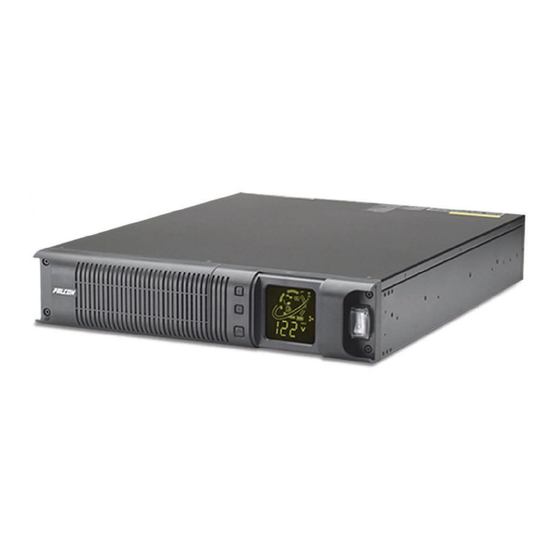
Page 13: Ups Overview
UPS Overview 1.5kVA to 3kVA Models Front View A: Battery Pack Compartment (1.5kVA only) D: Power / Bypass Button B: Function / Test Button E: LCD Display C: Set / Alarm Silence Button F: AC Power Switch... - Page 14 SSG1.5KRM-1 Rear View G H I SSG1.5KRM-2 Rear View G H I G: AC Power Cord Inlet L: Additional Battery Connection H: DB-9, RS232 M: Communication Option Slot I: USB N: UPS Output Panel J: Cooling Fan O: Remote Emergency Power Off (R.E.P.O)
- Page 15 SSG2.2KRM-1 / SSG3KRM-1 Rear View M H I SSG2.2KRM-2 / SSG3KRM-2 Rear View M H I G: AC Power Cord / Inlet L: Battery Connection H: DB-9, RS232 M: Communication Option Slot I: USB N: UPS Output Panel J: Cooling Fan O: Remote Emergency Power Off (R.E.P.O) Terminal...
- Page 16 SSG2.2KRM-1-HW / SSG2.2KRM-2-HW SSG3KRM-1-HW / SSG3KRM-2-HW Rear View M H I H: DB-9, RS232 M: Communication Option Slot I: USB N: UPS Output Panel J: Cooling Fan O: Remote Emergency Power Off (R.E.P.O) Terminal L: Battery Connection SSGR Rear View Q: Battery Circuit Breaker R: Additional Battery Connection S: Battery Connection...
- Page 17 SSGR-1 / SSGR-2 Rear View Q: Battery Circuit Breaker T: AC Power Switch R: Additional Battery Connection U: AC Power Cord Inlet with Fuse (3A / 250V) S: Battery Connection V: Daisy Chain Inlet (3A Max)
-
Page 18: Ups Component Overview
UPS Component Overview AC Power Cord / Inlet: Connector for line cord Output Panel: (Load Segment 1, Load or attached line cord that allows system Segment 2, Continuous Segment): Load connection to utility power. segments can be programmed to switch on or off during utility power loss to shed non-critical Battery Pack Compartment: Compartment loads whereas the continuous segment will... -
Page 19: Display & Controls
Display & Controls LCD Display The diagram to the right shows all available icons of the front panel LCD for the all SSG models. Refer to the LCD symbols in the left-hand column, below for their functional definition: Utility Power Status: Line cord icon indicates utility power is within specification. - Page 20 Front Panel Controls Function / Test Button: Multifunctional key performs the battery self-test and is used to scroll through bit options during UPS function setting. Set / Alarm Silence Button: Multifunctional key disables audible alarm, used to scroll through metered parameters and sets the desired programmed setting. Power / Bypass Button: Multifunctional key performs DC cold start to power UPS without utility power present, places UPS into bypass mode and is used to turn off UPS when utility power is lost.
-
Page 21: Getting Started
Getting Started Installation Environment The UPS can be installed as a standalone tower or rack mounted in a typical 19” equipment rack. Each UPS inverter and battery bank requires 2U (3.5” / 88.9mm) of vertical rack space. For equipment rack mounting, please refer to page 22 of this user’s manual. -
Page 22: Rackmount Installation
Rackmount Installation Securing hardware, slide rails (SGRMKIT) and rail extensions (DP70357) are sold separately. The UPS is designed to fit in a 19” equipment rack. Each UPS inverter module and battery bank requires 2U (3.5 inches / 88.9mm) of vertical rack space. The supplied rack mounting ears are intended to secure the units to the rack rails. - Page 23 For slide rail installation, fasten the inner portion of the slide rail to the UPS on both sides with the screws provided. (4) (8-32 x 3/16”) Follow any additional instructions that are included with the optional slide rail kit (SGRMKIT). Attach the two mounting brackets to the rack’s mounting rails.
- Page 24 Insert the UPS, with inner parts attached, into the slide assemblies. You may need to depress the locking mechanisms on the inner and outer parts of the slide assemblies to allow the slides to retract. The UPS should move smoothly forward and backward on the slide assemblies. If not, recheck alignment.
-
Page 25: Battery Pack / Bank Installation
Battery Pack / Bank Installation SSG1.5KRM Models Warning: Do not touch battery terminals located on the rear of the battery pack. Warning: Verify the battery fuse is not installed prior to installing battery pack. Note: The SSG1.5KRM UPS may be shipped with the battery pack preinstalled. 1. - Page 26 SSG2.2KRM / SSG3KRM Models Warning: Verify the battery circuit breaker is in the OFF (Down) position prior to battery installation. 1. Verify the battery circuit breaker is in the OFF (Down) position. 2. Loosen and remove the screws for the battery connection cover plates located on the rear panel of the UPS inverter and battery bank.
-
Page 27: Ups Start-Up Procedure
UPS Start-up Procedure SSG1.5KRM Models UPS shown for illustration purposes only, rear panel layout and operating voltage may vary. Battery Fuse Battery Pre-charge Button AC Power Cord Inlet 1. Remove the 30A / 250V fuse from the plastic bag attached to the fan grill on the UPS rear panel. - Page 28 SSG2.2KRM / SSG3KRM Models UPS shown for illustration purposes only, rear panel layout and operating voltage may vary. Battery Circuit Breaker Battery Cable 1. Place the battery circuit breaker in the ON (up) position. 2. Connect the supplied AC power cord to the UPS input plug inlet. (-2 Models) a.
- Page 29 Warning: Local and national electrical codes supersede all recommendations. Please adhere to local and national electrical codes. 2.2kVA to 3kVA Hardwire Terminal Input Output (L1) (L2) Ground (L1) (L2) Ground 120V Models - Current Ratings Model Max Current (Input) Model Max Current (Output) SSG2.2KRM-1-HW 16 Amps...
- Page 30 DC Start-up Procedure – Utility Power Unavailable Warning: Verify the connected equipment is turned off prior to starting procedure. Turn on the equipment after the UPS output has been turned on. Note: In the event utility power is not available, the UPS may be started up in battery mode. The UPS will operate on battery and supply power to the connected equipment until the batteries are depleted.
-
Page 31: Ups Operation
UPS Operation Operating Modes Online Mode Online mode operation indicates the load, inverter, PFC, line, charger and battery status. The fan is shown at medium speed. The dark, solid line inside the circle indicates the power flow from input, through the inverter, to load and from the input, to the charger and into the battery. - Page 32 Green Mode When green mode is activated, the UPS will automatically transfer to bypass mode once the connected load drops to less than 3% of the UPS’s rated output. The load will operate directly from utility power. The LCD will indicate the UPS is in bypass mode and the green mode bulb icon will be flashing.
- Page 33 LCD Meter Use the set / alarm silence button to scroll through the available meter readings. Input Voltage Output Voltage Output Frequency Battery Voltage Load Percentage Input Current Percentage Internal Temperature (Celsius) Output Current...
- Page 34 / defective or installed incorrectly, the battery pack is not installed, the battery bank interconnect cable is not installed, or the battery fuse is missing / defective. If the problem cannot be resolved, contact Falcon Service.
- Page 35 Programming Mode The following section describes how to configure the UPS setup options using the setup, configuration & programming mode. The setup options include: Programming the UPS output voltage. Enabling or disabling load segment controls. Enabling or disabling green mode function. Warning: Do not change the output voltage setting while powering the connected load.
- Page 36 Default Programmed Settings 120V Models Function Bit LSC #2 LSC #2 LSC #1 LSC #1 Green Mode 120V Output Disabled Disabled Disabled Disabled Disabled 230V Models Function Bit LSC #2 LSC #2 LSC #1 LSC #1 Green Mode 230V Output Disabled Disabled Disabled...
-
Page 37: Communications
Communications Communication Features RS-232 & USB The SSG UPS is equipped with (1) RS-232 and (1) USB port located on the UPS rear panel. A proprietary RS-232 interface cable is provided to allow the UPS to be connected to a workstation. The USB port interfaces with a standard USB cable to be supplied by the end-user. -
Page 38: Dry Contact Relay Cards
Dry Contact Relay Cards UA88376-SSG, DB-9 Version Warning: Do not change the default jumper settings of jumpers J1 to J7. The jumpers must all remain in the 1 – 2, default setting otherwise the relay card will not function properly. The pin designations table provides relay contact positions while the UPS is turned on and in online mode operation. - Page 39 UA88376-SSG-HW, Hardwire Terminal Version Warning: Do not change the default jumper settings of jumpers J1 to J7. The jumpers must all remain in the 1 – 2, default setting otherwise the relay card will not function properly. The pin designations table provides relay contact positions while the UPS is turned on and in online mode operation.
-
Page 40: Batteries
Batteries Safety IMPORTANT SAFETY INSTRUCTIONS SAVE THESE INSTRUCTIONS CAUTION: RISK OF EXPLOSION IF BATTERY IS REPLACED BY AN INCORRECT TYPE. When replacing batteries, replace with the same number of the following battery: Hitachi Chemical / CSB, XTV1272 F2 CAUTION: Risk of Energy Hazard, 12V, 7 Ampere-hour battery. Before replacing batteries remove conductive jewelry such as chains, wrist watches, and rings. -
Page 41: Battery Information
The depleted batteries or packs may be returned to the Falcon Service Center at the end user’s expense for recycling. Prior to returning the depleted batteries or packs, please contact the Falcon Service Center and obtain a Return Material Authorization (RMA) number. -
Page 42: Battery Pack Replacement
Battery Service Life (Float / Trickle Charge) The table below provides the typical battery service life during float / trickle charge. Ambient temperature greatly affects the overall battery life. Period Float Temperature (Years) Charge 25°C / 77°F 2.275Vdc 40°C / 104°F per cell 50°C / 122°F Battery Pack Replacement... - Page 43 SSG2.2KRM / SSG3KRM Models Warning: Do not touch battery terminals located on the rear of the battery pack. 1. Remove the plastic front panel on the left side first and battery support plate as shown. 2. Remove the battery packs. (Grasp each battery pack from the sides. Do not place hands on rear.) 3.
-
Page 44: Troubleshooting
Troubleshooting Alarms Audible Alarms The UPS features audible alarm codes to alert the user of potential problems. Please refer to the following table to identify and resolve alarms. Alarm Possible Cause Solution The UPS is in battery mode, Three short beeps, continuously Utility voltage check the utility power. - Page 45 Troubleshooting Tips Prior to attempting any troubleshooting, always verify the UPS battery fuse is installed and the input voltage, input plug and wiring are correct. Please refer to the table below. Problem Possible Cause Solution Verify the UPS input switch on front panel is turned on.
- Page 46 CPU detects error due to excessive OUT OF TOLERANCE – Restart UPS. If load variation. LOW RANGE error persists, CPU detects error due to excessive contact Falcon INVERTER overload or direct short on the UPS Electric Service OVERCURRENT output. Department.
-
Page 47: Technical Support
Falcon Electric will not assume any responsibility for shipping damage. In the event shipping damage is found, you will be notified of the damage and be instructed to file a claim with the freight carrier. You may be billed for all required repairs due to the shipping damage. -
Page 48: Warranty
Falcon with an RMA number. For defective product sold domestically, as defined above, returned within 30 days of shipment, Falcon will pay for the shipping costs to and from its service center. For a defective product returned after 30 days but within 90 days of shipment, Falcon will only pay for shipping costs in sending the new or repaired product back to the end-user.
Need help?
Do you have a question about the SSG1.5KRM-2 and is the answer not in the manual?
Questions and answers