Table of Contents
Advertisement
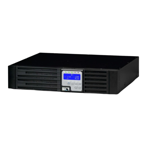
Rack / Tower Models
700VA to 3kVA, 120Vac
Proprietary: The information contained herein is proprietary to Falcon Electric, Inc. and
shall not be reproduced or disclosed in whole or in part or used for any reason except
when such user possesses direct, written authorization from Falcon Electric, Inc.
The statements contained herein are based on good faith assumptions and provided for
general information purposes only. These statements do not constitute an offer, promise,
warranty or guarantee of performance. Actual results may vary depending on certain
events or conditions. This document should not be used or relied upon for any purpose
other than that intended by Falcon Electric, Inc.
© 2016 Falcon® Electric, Inc. All rights reserved.
All other brand names and trademarks are the property of their respective owners.
The information stated in this document is subject to change without notice.
Falcon®, Falcon® Electric and UPS logos are registered trademarks of Falcon Electric, Inc.
OM480039 SC1-3KR_T 120V_12-12-16 REV.NR
SC On-line UPS
User's Manual
Advertisement
Table of Contents


Need help?
Do you have a question about the SG700RM-1SC and is the answer not in the manual?
Questions and answers