Table of Contents
Advertisement
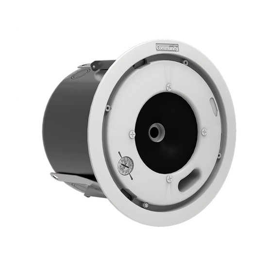
Distributed Design Series
Coaxial Ceiling Loudspeakers
Installation and Operation Manual
D10
D4LP
Model
D4
D5
D6
D8
D10
D10SUB
High-Fidelity
4.5"
114.3 mm
Diameter
4.5"
114.3 mm
5.0"
127 mm
6.5"
165.1 mm
8.0"
203.2 mm
10.0"
254.0 mm
10.0"
254.0 mm
full-range, low profile
Description
full-range
full-range
full-range
full-range
full-range
subwoofer
™
D10SUB
Advertisement
Table of Contents

Related Manuals for Community Distributed Design D4LP


Summary of Contents for Community Distributed Design D4LP
- Page 1 Distributed Design Series ™ High-Fidelity Coaxial Ceiling Loudspeakers Installation and Operation Manual D10SUB D4LP 4.5” 114.3 mm full-range, low profile Model Diameter Description 4.5” 114.3 mm full-range 5.0” 127 mm full-range 6.5” 165.1 mm full-range 8.0” 203.2 mm full-range D10 10.0” 254.0 mm full-range D10SUB 10.0” 254.0 mm subwoofer...
- Page 2 Distributed Design baffles are very close The Distributed Design Series is comprised to the grille (less than 1/8 inch away). The of these seven models: loudspeaker baffle and ceiling thus form an uninterrupted planar surface for diffraction- free HF driver acoustic loading and a smooth, Model Diameter Response predictable pattern. This makes it easy to lay D4LP 4.5” 114.3 mm full-range out your loudspeaker installation for opti- 4.5” 114.3 mm full-range mum coverage without those unwanted dead 5.0” 127 mm full-range zones or too-loud overlaps. 6.5” 165.1 mm full-range 8.0” 203.2 mm full-range The Distributed Design Series saves you D10 10.0”...
-
Page 3: Table Of Contents
Consequential and Incidental Damages: . . . . . . . . . . . . . . . . . . . . . . . . . . . . . . . 32 Warranty Information and Service for Countries Other Than the USA . . . . . . . . . . . . 32 This manual, including all images, is copyright 2010 by Community Professional Loudspeakers, Chester, Pennsylvania, USA. All Rights Reserved. Community Distributed Design Series Installation and Operation Manual... - Page 4 Figure 6. D4-FO Loudspeaker Dimensions . . . . . . . . . . . . . . . . . . . . . . . . . . . . . . 14 Figure 7. D4LP-BC Back Can Dimensions . . . . . . . . . . . . . . . . . . . . . . . . . . . . . . . 14 Figure 8. D5-FO Loudspeaker Dimensions . . . . . . . . . . . . . . . . . . . . . . . . . . . . . . 15...
-
Page 5: Important Safety Instructions
IMPORTANT SAFETY INSTRUCTIONS Always follow these basic safety precautions distributor, or call Community directly for as- when using or installing Distributed Design sistance. These terms are defined below: loudspeakers and accessories: • Read these instructions. tion or user action that may expose the CAUTION: describes an operating condi- equipment or user to potential damage • Keep these instructions. or danger. • Heed all warnings. tion or user action that will likely cause • Follow all instructions, particularly WARNING: describes an operating condi- damage to the equipment or injury to the those pertaining to rigging, mounting, user or to others in the vicinity. hanging and electrical connections. • Do not use this apparatus near water. tion or user action that will immediately DANGER: describes an operating condi- damage the equipment and/or be ex- • Clean only with dry cloth. tremely dangerous or life threatening to the user or to others in the vicinity. • Do not block any ventilation openings. Install in accordance with the manufac- ____________________________________________________ turer’s instruction. • Do not install near any heat sources of fire or electric shock, do not such as radiators, heat registers, stoves, WARNING: To reduce the risk expose this apparatus to rain or or other apparatus (including amplifiers) moisture. -
Page 6: L'information De Sûreté Importante
• Référez tout entretient au personnel ment que ce qui est contenu dans les instruc- qualifié de service. Ceci est exigé quand tions d’opérations à moins que vous êtes quali- l’appareil a été endommagé de quelque fié pour le faire. façon, incluant le fil d’alimentation et ou l’embout du fil a été endommagé, des liq- Les haut-parleurs décrits en ce manuel sont uides ont été renversés ou des objets sont conçus pour être accroché ou suspendus afin tombé à l’intérieur de l’appareil, l’appareil d’atteindre une exécution acoustique maximum a été exposé à la pluie ou l’humidité, en utilisant une série de differents matériaux, l’appareil ne fonctionne pas normalement moyens, et méthodes de calage dans certaines ou a été échappé. applications. Il est essentiel que tout le travail d’installation impliquant la suspension de ces Les termes attention, avertissement, et danger produits de haut-parleur soit effectué de facon peut être utilises dans ce manuel pour alerter securitaire par des personnes compétentes et le lecteur aux considérations importantes de bien formées dans les methodes de calage. Des sûreté. Si vous avez des questions ou ne com- blessures graves et/ou des pertes humaines prenez pas la signification de ces termes, ne peuvent se produire si ces produits sont incor- procédez pas à l’installation. Contactez votre rectement installés. Veuillez lire la section sur le detaillant, distributeur, ou Community directe- câblage et l’installation pour des informations ment pour assistance. Les termes sont définies supplémentaires. ci-dessous: Community Distributed Design Series Installation and Operation Manual Page 6... -
Page 7: Unpacking And Inspection
UNPACKING AND INSPECTION Community Distributed Design loudspeakers nied if these materials are not retained. Your are engineered and manufactured to be rug- Community dealer and the factory will try to ged and they are carefully packed in sturdy help in any way they can, but it is the respon- cartons. However, it is wise to thoroughly sibility of the party receiving the shipment to inspect each unit after it has been removed file the damage claim. from the packaging, as damage could occur It’s always a good idea to retain the carton during shipping. and packing materials indefinitely, if pos- Please note that once the shipment has left sible, in the event that the unit may need to your dealer or the Community factory, the be returned to your dealer or distributor for responsibility for damage is always borne repair in the future. by the freight company. If damage has oc- For each of the seven models in the curred during shipping, you must file a claim Distributed Design Series, it is possible to directly with the freight company. It’s very order a full Ceiling Loudspeaker Assembly, a important to contact the freight company as soon as possible after receiving your ship- Consult the three lists (beginning on the next ment, as most freight companies have a short Face-Only Assembly or a Back Can Assembly. page) to find the contents of each carton time limit within which they will investigate for the version of the assembly you have claims. Make sure to save the carton and the... -
Page 8: Option 1: Full Ceiling Loudspeaker Assembly
• Grilles (Qty 2) • C-Ring Support Plates (Qty 2) (Models: D4LP, D4, D5, D6, D8, D10, D10SUB) Option 1: Full Ceiling Loudspeaker Assembly* • Ceiling Loudspeaker Assembly (Qty 2) • Cut-out template (can-sized) (Qty 1) • Back cans (Qty 2) • Paint Masks (Qty 2) • Tile Support Bridge Rails (Qty 4) • Flat screwdriver (Qty 1) (for screws, con- nectors and to help remove the grille) Grilles Loudspeakers (secured in their back cans) C-Ring Support Plates Tile Support Bridge Rails Cut-out Template Paint Masks Flat screwdriver Figure 1 Full Ceiling Loudspeaker assembly package contents (typical) Note: These illustrations are typical. -
Page 9: Unpacking And Inspection Option 2: Face Only
• Cut-out template (can-sized) (Qty 1) • Flat screwdriver (Qty 1) (for screws, con- (Models: D4-FO, D5-FO, D6-FO, D8-FO, D10-FO, Option 2: Face Only nector and to help remove the grille) D10SUB-FO) • Ceiling Loudspeakers (Qty 2) • Grilles (Qty 2) • Paint Masks (Qty 2) Loudspeakers Grilles Cut-out Paint Masks Template Flat screwdriver Figure 2 Face Only package contents (typical) Community Distributed Design Series Installation and Operation Manual Page 9... -
Page 10: Option 3: Back Can
(Models: D4LP-BC, D45-BC, D6-BC, D8-BC, D10-BC) Option 3: Back Can • Back cans (Qty 2) • Tile Support Bridge Rails (Qty 4) • C-Ring Support Plates (Qty 2) • Cut-out template (can-sized) (Qty 1) • Flat screwdriver (Qty 1) (for screws, con- nectors and to help remove the grille) Back Cans C-Ring Support Plates Tile Support Bridge Rails Cut-out Template Flat screwdriver Figure 3 Back Can package contents (typical) Community Distributed Design Series Installation and Operation Manual Page 10... -
Page 11: Optional Accessories
New Construction Bracket Can Adapter/Trim Ring Face Adapter Ring (without and with screw hole plugs) Figure 4 Optional Accessories Ceiling Loudspeaker Packages Adapter Rings Brackets 4.5” Low Pro. D4LP D4LP-BC Size Assembled Back Can Only Face Only Face Can Adapter/Trim New Construction D4-FO 4.5”... -
Page 12: Specifications
Specifications Community Distributed Design Series Installation and Operation Manual Page 12... -
Page 13: Safety Agency Compliance
For protection against electrical shock and to meet the requirements of the UL2043 standard, the speaker assembly must be installed in the appropriate Listed Community Distributed Design Series Back Box or similar UL1480/UL2043 Listed enclosure Minimum dimensions for the enclosure for each model must be:... -
Page 14: Figure 5 D45-Bc Back Can Dimensions
Figure 5 D45-BC Back Can Dimensions Figure 7 D4LP-BC Back Can Dimensions Figure 6 D4-FO Loudspeaker Dimensions Note: The same (D4-FO) Loudspeaker face assembly is used for the D4 and D4LP as these models differ only with respect to their back cans. Community Distributed Design Series Installation and Operation Manual... -
Page 15: Figure 8. D5-Fo Loudspeaker Dimensions
Figure 8 D5-FO Loudspeaker Dimensions Figure 9 D6-BC Back Can Dimensions Note: The D5-FO uses the same sions Figure 10 D6-FO Loudspeaker Dimen (D45-BC) back can as the D4-FO. Community Distributed Design Series Installation and Operation Manual Page 15... -
Page 16: Figure 11. D8-Bc Back Can Dimensions
Figure 11 D8-BC Back Can Dimensions Figure 13 D10-BC Back Can Dimensions Figure 14 D10-FO Loudspeaker Dimensions Figure 12 D8-FO Loudspeaker Dimensions Community Distributed Design Series Installation and Operation Manual Page 16... -
Page 17: Figure 15 D10Sub-Fo Loudspeaker Dimensions
Figure 15 D10SUB-FO Loudspeaker Dimensions Figure 16 Face Adapter Ring Detail Note: The D10SUB-FO loud- speaker uses the same (D10-BC) back can as the D10-FO loud- speaker. Figure 17 Can Adapter/Trim Ring Detail Community Distributed Design Series Installation and Operation Manual Page 17... -
Page 18: Component Identification
(4) Loudspeaker In- Lock Clamp Alignment put Connector on Slot (4 typical) Used Phillips-head Can-Locking circuit board to align face in proper Clamp Actuator (4) location when installing back can Figure 18 Component Part Identification (1) Community Distributed Design Series Installation and Operation Manual Page 18... -
Page 19: Figure 19. Component Part Identification (2)
Metal safety clip and high-impact mono filament nylon loops that secure grille to loudspeaker face Mounting screw holes on optional face adapter ring (left) and optional can adapter/trim ring (right) Figure 19 Component Part Identification (2) Community Distributed Design Series Installation and Operation Manual Page 19... -
Page 20: Power Determination
(or wall) after we describe the general means to wire the cans and loudspeakers. This manual will serve to assist in wiring and physically mounting Distributed Design Se- The only tool required is a screwdriver, ries loudspeakers. The directions include as- Installation in back cans without conduit which is provided in the Loudspeaker sistance to those installers using a complete package. Distributed Design back cans Community package of loudspeakers and ac- include a swivel-out terminal access cover cessories, including the back cans, grilles, tile that also serves as a cable clamp when rails and so forth. We include instructions tightened in place. The terminal block in the for use of optional Community Distributed can’s outer recess has two (+) connections Design Series retrofit adapters so that Com- and two (-) connections. If you’re only munity Distributed Design Series loudspeak- connecting one (dual conductor) cable, ers can be mounted in other manufacturer’s... -
Page 21: Figure 21 Internal Wiring Between Can Terminal Block And Loudspeaker
The selection of appropriate electrical hardware to interface with the Distributed Design Series loudspeaker lies solely with the installation professional. Community recommends that an appro- priately licensed engineer, electrician, or other professional identify and select the appropriate conduit, fittings, wire, etc. -
Page 22: Installation Of Conduit To The Back Can
Figure 22 Conduit for Protected Wiring to Can When you use conduit to bring wires to the side port(s) of the back can, you can loosen the screws in the green plug to remove the factory-installed wires from the internal terminal block jumpers (see Figure 22), then insert wires from the conduit(s) and tighten the screws. In any case, the rest of the wiring details are the same as shown in Figure 21. Figure 23 Redeploying the plug for wires entering from conduit (Loosen clamping screws to remove wires) Community Distributed Design Series Installation and Operation Manual Page 22... -
Page 23: General
Installing the Back Can in the Ceiling You will of course lay out the loudspeaker General locations according to the requirements of the specific installation and in compliance with applicable safety and building codes. It is beyond the scope of this manual to pro- vide guidance in this area. Community does, however, offer our Forecaster ceiling system software to assist you in distributed loud- speaker system design. Please visit the Prod- uct Selection area of Community website for this software. We also encourage you to use the provided seismic safety tabs to secure the back cans to the building structure. Again, please be guided by applicable building codes here; we cannot provide detailed rigging instructions due to the wide global variations in such Figure 24 Cutout template dimensions codes and practices. Note: The bridge support rails each have a raised rib with a flat stabilizing flange on... -
Page 24: Figure 26. Drop-Stop Tabs (Highlighted) Snap Out Over C-Ring Support
Figure 27 Turning the can clamp hear them “snap” into position; you can now actuators clockwise securely locks the continue without having to hold the can in 6. This concludes a single back can installa- back can into the ceiling place. See Figure 26. tion for a standard suspended ceiling. Repeat for as many loudspeakers as you need to install. Refer to page 26 for instructions on install- ing the loudspeaker into the back can. Community Distributed Design Series Installation and Operation Manual Page 24... -
Page 25: Dry-Wall Ceiling Installation
Can Adapter/Trim Ring). While the latter port Rails. While there are in fact not going includes a shallow back can, both the D4 and to be truss members across which the rails D4LP use the same D4-FO loudspeaker which fit, nonetheless they will distribute the has a shallow depth. weight of the loudspeaker assembly across a greater area than the C-Ring Adapter Note: We do not offer a Face Adapter Ring for alone and will thus avoid sagging that our larger model loudspeakers. -
Page 26: Inserting The Loudspeaker Assembly Into The Back Can
Note. If you are thinking of using the Can Adapter/Trim Ring to fit a complete Community Loudspeaker Assembly into an existing oversize ceiling hole, please forget about it! We do not recommend this practice. The loudspeaker has minimal support and is more apt to cause the ceiling to sag. -
Page 27: Type Of Paint
It’s best to paint the baffle before installa- tion. In cases where it needs to be finished 3. After cleaning, apply two or more thin along with the ceiling, the loudspeaker baffle coats of either latex or oil-based paints. can be painted after mounting in the ceiling. Latex paint will adhere better if an oil-based primer is used first. Apply the paint with a roller or brush, or spray it on. Note: The paint masks provided by 4. The grille should be painted separately, Community are intended to PREVENT the and when it is not in place on the loudspeak- loudspeakers from receiving any paint. er. We further recommend that you remove The loudspeaker’s ABS plastic baffle accepts the grille foam, then spray paint the grille as- Type of Paint almost any type of latex or oil based paint. sembly. Avoid using a roller or brush to paint We recommend application of two coats. the grille as its metal perforated holes may... -
Page 28: Assembling The Loudspeaker Into The Back Can
Note: Some codes now require that the grille they are at the far right of the slots (viewed through the slot from the front of the loud- have a safety cable; your local codes may vary. In any case, Community makes it easy to speaker). comply with an included security cable system, 2. Twist the loudspeaker clockwise a few as detailed in Steps 4 through 6. -
Page 29: Figure 33 Grille Safety Clip And Line (Left) Should Look Like This (Right) When Attached
4. Once the loudspeaker is 6. If you’re proceeding with setup, you can secured in the back can, you can leave the grille hanging so you can adjust attach the safety cable between the the power setting as noted on the next page. grille and loudspeaker. There is a Otherwise, snap the grille into position on nylon mono filament loop attached the face of the loudspeaker baffle. to the grille and looped through a metal clip. Another mono filament line is located inside the bass reflex port of the face of the loudspeaker. Use the metal clip to link these two mono filament loops. See Figure 33. 5. Carefully lower the grille until the cable holds it, and let go. It should hang harmlessly from the mono filament line. Figure 33 Grille safety clip and line (left) should look like this (right) when attached Community Distributed Design Series Installation and Operation Manual Page 29... -
Page 30: Loudspeaker Tap Setting
70-volt source. settings. The 8-ohm position is the same on balance an installation since there is no need both sides and is for a low impedance con- to drop the loudspeakers out of their back nection. On the left side of Figure 34’s close- cans and move wires to different terminals. up detail view are the power values for 100- volt connections, and on the right side the power values for 70-volt connections. (The actual power values on this dial will vary with the model of loudspeaker installed.) Face-mounted, screwdriver-adjustable Enhanced detail of typical adjustor dial loudspeaker power / voltage setting dial (Available settings vary with model ) Figure 34 Setting Loudspeaker Tap Community Distributed Design Series Installation and Operation Manual Page 30... -
Page 31: Transferable Warranty "(Limited)
Warranty Information and Service To obtain factory or field warranty service for products purchased in the United States, return the product for inspection to the ad- Transferable Warranty “(Limited)” Community Distributed Design Series ceil- dress below, freight prepaid, in the original Valid in the USA Only ing loudspeakers are warranted in the USA packaging. If the original packaging is not to be free from manufacturing defects in available, call or write Community Warranty materials and workmanship for a period of Service to obtain proper packaging materi- five years, as determined by one of the fol- als or hand carry the product to the nearest lowing two methods, whichever is longer: Field Service Station. Starting from the date of retail purchase, as noted on the sales receipt from an autho- rized Community dealer, Community Warranty Service Factory Service Center: 333 East Fifth Street Chester, PA 19013-4511 USA Starting from the date of manufacture, de- termined by the serial number, if the sales Call (610) 876-3400 for the nearest Autho- receipt is not available. -
Page 32: Consequential And Incidental Damages
Community shall not be liable for any con- Consequential and Incidental Damages: sequential or incidental damages including, without limitation, injury to persons, prop- erty, or loss of use. Some states do not allow the exclusion or limitations of consequential or incidental damages, so the above limita- tions and exclusions may not apply. This Community warranty is not extended by the length of time which an owner is deprived of the use of the product. Repairs and replacement parts provided under the terms of this warranty shall carry only the remaining portion of the warranty. Community reserves the right to change the design of any product from time to time, without notice and with no obligation to make corresponding changes in products previously manufactured. While this warranty gives specific legal rights, there may also be other rights that vary from state to state. No action to enforce this warranty shall be permitted ninety days after expiration of the warranty period. Warranty Information and Service for Coun- To obtain specific warranty information tries Other Than the USA... - Page 33 - Notes - Community Distributed Design Series Installation and Operation Manual Page 33...
- Page 34 - Notes - Community Distributed Design Series Installation and Operation Manual Page 34...
- Page 35 - Notes - Community Distributed Design Series Installation and Operation Manual Page 35...
- Page 36 333 East Fifth Street, Chester, PA 19013-4511 USA Community Professional Loudspeakers Tel: 1-(610) 876-3400 | Fax: 1-(610)874-0190 www.communitypro.com © 2010 All Rights Reserved 23SEPT2010...
Need help?
Do you have a question about the Distributed Design D4LP and is the answer not in the manual?
Questions and answers