Sign In
Upload
Download
Table of Contents
Contents
Add to my manuals
Delete from my manuals
Share
URL of this page:
HTML Link:
Bookmark this page
Add
Manual will be automatically added to "My Manuals"
Print this page
×
Bookmark added
×
Added to my manuals
Manuals
Brands
Norton Manuals
Saw
Clipper C13PE
Owner's manual
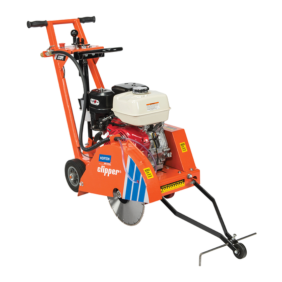
Norton Clipper C13PE Owner's Manual
Small concrete saw
Hide thumbs
1
2
Table Of Contents
3
4
5
6
7
8
9
10
11
12
13
14
15
16
17
18
19
20
21
22
23
24
25
26
27
28
29
30
31
32
33
34
35
36
page
of
36
Go
/
36
Contents
Table of Contents
Bookmarks
Table of Contents
Table of Contents
Contents
Preparation
Safety Precautions
Dust and Silica Warning
Assembly
Engine Precautions
Pointer Alignment
Operation
Blade Installation
Starting the Engine
C13PE 13HP Honda
C14PE 14HP Subaru
Water Supply
Operating the Saw
Cutting Technique
B. Starting the Engine
Maintenance
Engine
Wiring Diagram
C13PE 13HP Honda
C14PE 14HP Subaru
Bearings
V-Belts
Depth Control
F. Inspection and Cleaning
Parts List Section
Ordering Information
IV. Parts List Section A. Ordering Information
Depth Control and Depth Lock Group
Blade Guard and Water Control Group
Engine Group
Blade Shaft Group
Raise Axle Group
Main Frame and Belt Guard Group
Front Pointer Group
Advertisement
Quick Links
1
Blade Installation
2
V-Belts
3
Parts List Section
Download this manual
OWNERS
MANUAL
Small Concrete Saw
Models:
C13PE and C14PE
FORM: C13PE rev 3-2013
Table of
Contents
Previous
Page
Next
Page
1
2
3
4
5
Advertisement
Table of Contents
Need help?
Do you have a question about the Clipper C13PE and is the answer not in the manual?
Ask a question
Questions and answers
Related Manuals for Norton Clipper C13PE
Saw Norton C1320P Owner's Manual
Medium concrete saws (44 pages)
Saw Norton Clipper C14PE Owner's Manual
Small concrete saw (36 pages)
Saw Norton C1316 Owner's Manual
Medium concrete saws (50 pages)
Saw Norton Clipper C1318P Owner's Manual
Small concrete saw (34 pages)
Saw Norton Clipper C1418P Owner's Manual
Small concrete saw (44 pages)
Saw Norton C2020 Owner's Manual
Medium concrete saws (50 pages)
Saw Norton clipper CHW Series Operating Instructions Manual
(23 pages)
Saw Norton clipper CMR 351 Operating Instructions Manual
(20 pages)
Saw Norton clipper CP514-350 Translation Of The Original Instructions
(42 pages)
Saw Norton Clipper CS 401 P13 Operating Instructions Manual
(28 pages)
Saw Norton clipper CM 352 Operating Instructions Manual
(24 pages)
Saw Norton clipper CM 450 Junior Operating Instructions Manual
(24 pages)
Saw Norton clipper CS1-500 P13 Operating Instructions Manual
(28 pages)
Saw Norton clipper CS 352 Operating Instructions Manual
(28 pages)
Saw Norton Clipper C35 Series Operator's Manual
Self propelled saw (25 pages)
Saw Norton clipper CM 400 Junior Operating Instructions Manual
(24 pages)
This manual is also suitable for:
Clipper c14pe
Table of Contents
Print
Rename the bookmark
Delete bookmark?
Delete from my manuals?
Login
Sign In
OR
Sign in with Facebook
Sign in with Google
Upload manual
Upload from disk
Upload from URL


Need help?
Do you have a question about the Clipper C13PE and is the answer not in the manual?
Questions and answers