
Related Manuals for Allied Telesis AT-CM20x Series


Summary of Contents for Allied Telesis AT-CM20x Series
- Page 1 CONVERTEON™ Family Media Converter Line Cards AT-CM20x Series AT-CM212x/1 Series AT-CM2K0S AT-CV10x Series AT-CV1KSS AT-CM70S Reference Guide 613-50581-00 Rev. D...
- Page 2 Allied Telesis, Inc. reserves the right to make changes in specifications and other information contained in this document without prior written notice. The information provided herein is subject to change without notice. In no event shall Allied Telesis, Inc. be liable for any incidental, special, indirect, or consequential damages whatsoever, including but not limited to lost profits, arising out of or related to this manual or the information contained herein, even if Allied Telesis, Inc.
-
Page 3: Electrical Safety And Emissions Standards
Electrical Safety and Emissions Standards Standards: This product meets the following standards when installed in compliant host equipment. U.S. Federal Communications Commission Radiated Energy Note: This equipment has been tested and found to comply with the limits for a Class A digital device pursuant to Part 15 of FCC Rules. - Page 4 Electrical Safety and Emissions Standards Translated Safety Statements Important: Appendix C contains translated safety statements for installing this equipment. When you see the , go to Appendix C for the translated safety statement in your language. Wichtig: Anhang C enthält übersetzte Sicherheitshinweise für die Installation dieses Geräts. Wenn sehen, schlagen Sie in Anhang C den übersetzten Sicherheitshinweis in Ihrer Sprache nach.
-
Page 5: Table Of Contents
Preface ....................................11 How This Guide is Organized .............................. 11 Document Conventions ............................... 12 Where to Find Web-based Guides ............................13 Contacting Allied Telesis ..............................14 Online Support ................................14 Email and Telephone Support ............................14 Returning Products............................... 14 For Sales or Corporate Information ..........................14 Obtaining Management Software Updates.......................... - Page 6 Link Test ..................................44 MissingLink™ ................................44 Smart MissingLink ................................ 45 OAM Overview ................................45 AT-CM20x Series and AT-CM212x/1 Series Line Cards....................50 AT-CV10x Series Line Cards............................52 AT-CM2K0S Line Card ..............................53 AT-CV1KSS Line Card ..............................54 AT-CM70S Line Card ..............................55 FCC Part 68 Customer Information ..........................
- Page 7 Converteon Media Converter Line Cards Reference Guide Appendix A: Technical Specifications ..........................85 Physical Specifications ................................ 85 Environmental Specifications............................... 85 Electrical Specifications ............................... 86 Optical Specifications ................................87 Safety and Electromagnetic Emissions Certifications......................88 RJ-45 Twisted Pair Port Pinouts............................89 RJ-48 T1/E1 Port Pinouts ..............................
-
Page 8: Figures
Figure 6. AT-CM70S Line Card ............................25 Figure 7. SFP Transceiver Module ............................ 35 Figure 8. DIP Switches on an AT-CM20x Series Line Card (AT-CM202) ................. 50 Figure 9. DIP Switches on an AT-CM212x/1 Series Line Card ..................50 Figure 10. DIP Switches on an AT-CM20x Series Line Card .................... 52 Figure 11. - Page 9 Converteon Media Converter Line Cards Reference Guide Figure 51. Ferrule in an SC Connector Plug........................106 Figure 52. Unclean and Clean Ferrule..........................106 Figure 53. Cartridge Cleaner ............................107 Figure 54. Rubbing the Ferrule Tip on the Cleaning Surface ..................107 Figure 55.
-
Page 10: Tables
Table 11. OAM Active and Passive Mode Behaviors ......................49 Table 12. AT-CM20x Series and AT-CM212x/1 Series – Diagnostic Mode DIP Switch 1 Positions ......... 50 Table 13. AT-CM20x Series and AT-CM212x/1 Series – Port Configuration DIP Switch 2 Positions ....... 51 Table 14. -
Page 11: Preface
Appendix C, ”Translated Safety Statements” on page 111 This preface contains the following sections: “Document Conventions” on page 12 “Where to Find Web-based Guides” on page 13 “Contacting Allied Telesis” on page 14 “Obtaining Management Software Updates” on page 15... -
Page 12: Document Conventions
Preface Document Conventions This document uses the following conventions: Note Notes provide additional information. Caution Cautions inform you that performing or omitting a specific action may result in equipment damage or loss of data. Warning Warnings inform you that performing or omitting a specific action may result in bodily injury. -
Page 13: Where To Find Web-Based Guides
Converteon Media Converter Line Cards Reference Guide Where to Find Web-based Guides The installation and user guides for all Allied Telesis products are available in portable document format (PDF) from the Allied Telesis web site at www.alliedtelesis.com. You can view the documents online or download them onto a local workstation or server. -
Page 14: Contacting Allied Telesis
Knowledge Base to submit questions to our technical support staff and review answers to previously asked questions. Email and For Technical Support via email or telephone, refer to the Allied Telesis web site: http://www.alliedtelesis.com. Select your country from the list Telephone displayed on the website. -
Page 15: Obtaining Management Software Updates
Allied Telesis web site: www.alliedtelesis.com Allied Telesis FTP server: ftp://ftp.alliedtelesis.com If you prefer to download new software from the Allied Telesis FTP server using your workstation’s command prompt, you will need FTP client software and you must log in to the server. Enter “anonymous” as the user... -
Page 16: Chapter 1: Converteon™ Fast Ethernet And Gigabit Ethernet Line Cards
Chapter 1 Converteon™ Fast Ethernet and Gigabit Ethernet Line Cards This chapter contains the following sections: “Overview” on page 17 “Line Card Descriptions” on page 19 “Hardware Features” on page 26 “100Base-FX Fiber Optic Ports” on page 27 “10/100Base-TX Twisted Pair Ports” on page 29 “10/100/1000Base-T Twisted Pair Ports”... -
Page 17: Overview
Converteon Media Converter Line Cards Reference Guide Overview Table 1 lists the configurations of the line cards that are currently available to be used with any Converteon™ Media Converter Chassis. Table 1. Basic Line Card Configurations Type of Maximum Line Card Connector Cable Speed... - Page 18 Chapter 1: Converteon™ Fast Ethernet and Gigabit Ethernet Line Cards Table 1. Basic Line Card Configurations Type of Maximum Line Card Connector Cable Speed Port/Slot Distance AT-CV101 Fiber Optic Dual ST 50/125 or 100 Mbps 2 kilometers 62.5/125 micron (1.24 miles) Multi-Mode Copper RJ-45...
-
Page 19: Line Card Descriptions
Converteon Media Converter Line Cards Reference Guide Line Card Descriptions AT-CM20x Series The AT-CM20x Series line cards are 10/100 Mbps copper-to-fiber media converter line cards. These line cards can be installed in any of the Converteon™ Media Converter chassis, including the AT-CV5000, AT-CV1000, and AT-CV1200. -
Page 20: At-Cm212X/1 Series
Chapter 1: Converteon™ Fast Ethernet and Gigabit Ethernet Line Cards AT-CM212x/1 The AT-CM212x/1 Series (AT-CM212A/1 and AT-CM212B/1) are 100 Mbps copper-to-fiber media converter line cards. The line card contains Series one fiber optic port and one copper twisted pair port. The fiber optic port operates at a fixed operating speed of 100 megabits per second (Mbps) and the twisted pair port operates at 10 or 100 Mbps speed. -
Page 21: At-Cm2K0S
Converteon Media Converter Line Cards Reference Guide AT-CM2K0S The AT-CM2K0S is a Gigabit copper-to-fiber media converter line card. This line card can be installed in any of the Converteon™ Media Converter chassis, including the AT-CV5000, AT-CV1000, and AT-CV1200. The line card features one small form-factor pluggable (SFP) transceiver slot and one copper twisted pair port. -
Page 22: At-Cv10X Series
Chapter 1: Converteon™ Fast Ethernet and Gigabit Ethernet Line Cards AT-CV10x Series The AT-CV10x Series (AT-CV101, AT-CV102, AT-CV102/1, and AT-CV102/2) are 100 Mbps copper-to-fiber media converter line cards. The line card features one fiber optic port and one copper twisted pair port. - Page 23 Converteon Media Converter Line Cards Reference Guide Note Restriction of Operation: While operating two AT-CV102 line cards back-to-back, where both cards are in SML mode, if the fiber connection between them is broken, remove the copper connection to one of the AT-CV102 cards before restoring the fiber link between them.
-
Page 24: At-Cv1Kss
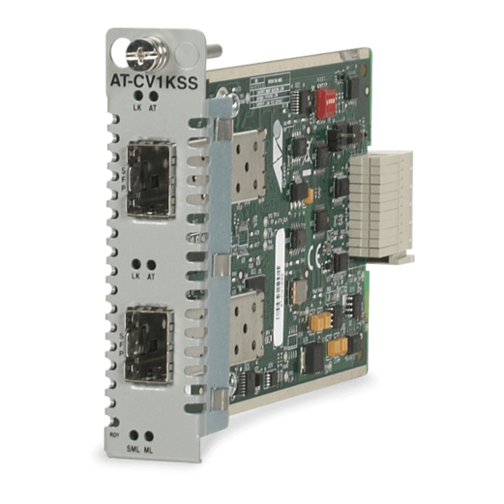
Chapter 1: Converteon™ Fast Ethernet and Gigabit Ethernet Line Cards AT-CV1KSS The AT-CV1KSS, shown in Figure 5, is a Gigabit fiber-to-fiber media converter line card used for Ethernet based networks. The line card features two small form-factor pluggable (SFP) transceiver slots. Each SFP slot can accommodate one SFP transceiver that operates at a fixed operating speed of one Gigabit. -
Page 25: At-Cm70S
Converteon Media Converter Line Cards Reference Guide AT-CM70S The AT-CM70S is a 10/100 Mbps Ethernet copper-to-fiber media converter line card with Time Division Multiplexing (TDM) (T1/E1) transport in addition to regular Ethernet traffic along with OAM link management capability. This line card offers support for 1.544 Mbps (T1) and 2.048 Mbps (E1) services - with complete synchronization for toll- quality transport of voice, video, and data. -
Page 26: Hardware Features
Chapter 1: Converteon™ Fast Ethernet and Gigabit Ethernet Line Cards Hardware Features The following sections describe these hardware features of the Converteon™ media converter line cards: “100Base-FX Fiber Optic Ports” on page 27 “10/100Base-TX Twisted Pair Ports” on page 29 “10/100/1000Base-T Twisted Pair Ports”... -
Page 27: 100Base-Fx Fiber Optic Ports
100 Mbps. The speed cannot be changed. The ports can send and receive on the following wavelengths: AT-CM20x Series – TX/RX=1310 nm AT-CM212A/1 – TX=1310 nm and RX=1550 nm AT-CM212B/1 – TX=1550 nm and RX=1310 nm AT-CV10x Series –TX/RX=1310 nm... -
Page 28: Type Of Cable
Chapter 1: Converteon™ Fast Ethernet and Gigabit Ethernet Line Cards Type of Cable The fiber optic ports on the Converteon™ line cards use either a single- mode (9/125 micron) or a multi-mode (50/125 or 62.5/125 micron) fiber optic cable. AT-CM202 – Multi-mode AT-CM202/1 –... -
Page 29: 10/100Base-Tx Twisted Pair Ports
Converteon Media Converter Line Cards Reference Guide 10/100Base-TX Twisted Pair Ports The 10/100Base-TX twisted pair ports featured on the Converteon™ line cards are described below. Type of The 10/100Base-TX twisted pair ports feature 8-pin RJ-45 connectors. Only four of the pins are used when a port is operating at 10 or 100 Mbps. Connector For the port pinouts, refer to “RJ-45 Twisted Pair Port Pinouts”... -
Page 30: Auto Mdi/Mdi-X
Chapter 1: Converteon™ Fast Ethernet and Gigabit Ethernet Line Cards Auto MDI/ The 10/100Base-TX twisted pair ports are auto-MDI/MDI-X. They automatically configure themselves as either MDI or MDI-X, depending on MDI-X the configuration of the port on the end node. This feature allows you to use either straight-through or crossover twisted pair cables to connect devices to the ports. -
Page 31: 10/100/1000Base-T Twisted Pair Ports
Converteon Media Converter Line Cards Reference Guide 10/100/1000Base-T Twisted Pair Ports The 10/100/1000Base-T twisted pair ports featured on the Converteon™ line cards are described below. Type of The ports have 8-pin RJ-45 connectors. The ports use four pins when operating at 10 or 100 Mbps and all eight pins when operating at 1000 Connector Mbps. -
Page 32: Port Pinouts
Chapter 1: Converteon™ Fast Ethernet and Gigabit Ethernet Line Cards Port Pinouts For the pinouts of these ports when operating at 10 or 100 Mbps, refer to Table 10 on page 82. For port pinouts when the ports are operating at 1000 Mbps, refer to Table 12 on page 84. -
Page 33: T1/E1 Port (At-Cm70S Line Cards Only)
Converteon Media Converter Line Cards Reference Guide T1/E1 Port (AT-CM70S Line Cards Only) The T1/E1 twisted pair ports featured on the AT-CM70S line cards are described below. Type of The T1/E1 ports on the AT-CM70S line cards feature 8-pin RJ-48 connectors. -
Page 34: Console Port (At-Cm70S Line Card Only)
Chapter 1: Converteon™ Fast Ethernet and Gigabit Ethernet Line Cards RS-232 Console Port (AT-CM70S Line Card Only) You can use the console port on the AT-CM70S line card to establish a local (out-of-band) management session with the chassis to configure parameters and also view information about the operating of the system and line cards. -
Page 35: Sfp Expansion Slots
Converteon Media Converter Line Cards Reference Guide SFP Expansion Slots The SFP expansion slots featured on the Converteon™ line cards are described below. The SFP modules are a fast and easy way for you to add an 1000 Mbps fiber optic port. You can use the modules to extend the distance of your network, build a high-speed backbone network between devices, or connect additional end nodes to the network, such as high-speed servers. -
Page 36: Line Card And Port Status Leds
Chapter 1: Converteon™ Fast Ethernet and Gigabit Ethernet Line Cards Line Card and Port Status LEDs Line Card Status The front panels of the Converteon™ line cards have different status LEDs, depending on the model. These LEDs display the status LEDs information of the line cards. -
Page 37: Table 3. At-Cm70S Line Card Status Leds
Converteon Media Converter Line Cards Reference Guide Table 3 lists the status LEDs on the AT-CM70S line card. Table 3. AT-CM70S Line Card Status LEDs State Description Green The line card has passed diagnostics. The line card has not passed diagnostics. -
Page 38: Fiber Optic Port Leds
Chapter 1: Converteon™ Fast Ethernet and Gigabit Ethernet Line Cards Fiber Optic Port Table 4 lists the fiber optic port LEDs, except for AT-CM70S line card. For LEDs on the AT-CM70S line card, refer to Table 5. LEDs Table 4. Line Card Fiber Optic Port LEDs State Description Green... -
Page 39: Twisted Pair Port Leds
Converteon Media Converter Line Cards Reference Guide Twisted Pair Port Table 6 lists the twisted pair port LEDs, except for AT-CM70S line card. For LEDs on the AT-CM70S line card, refer to Table 7. LEDs Table 6. Line Card Twisted Pair Port LEDs State Description Green... - Page 40 Chapter 1: Converteon™ Fast Ethernet and Gigabit Ethernet Line Cards Table 7. AT-CM70S - Twisted Pair Port LEDs State Description Green The TX port is operating at 100 Mbps speed. The TX port is operating at 10 Mbps speed.
-
Page 41: T1/E1 Port Leds
Converteon Media Converter Line Cards Reference Guide T1/E1 Port LEDs Table 9 lists the T1/E1 surface-mount diagnostic LED’s provisioned on the Mezzanine Adapter and are viewable through the line card front panel. Table 8. T1/E1 Port LEDs State Description Amber Receive Carrier Loss occurred on the [1 to 4] T1/E1 port. -
Page 42: Serial Port Leds
Chapter 1: Converteon™ Fast Ethernet and Gigabit Ethernet Line Cards Serial Port LEDs Table 9 lists the serial port LED’s provisioned on the Mezzanine Adapter and are viewable through the line card front panel. Color Description SER MODE Green The serial port is operating in RS-232 mode. [1 to 4] The serial port is operating in RS-422/485 mode. -
Page 43: Sfp Transceiver Leds
Converteon Media Converter Line Cards Reference Guide SFP Transceiver Table 9 lists the SFP transceiver LEDs, except for AT-CM70S line cards. For LEDs on the AT-CM70S line cards, refer to Table 10 LEDs Table 9. SFP Transceiver LEDs State Description Green Link established on the port. -
Page 44: Dip Switches
Chapter 1: Converteon™ Fast Ethernet and Gigabit Ethernet Line Cards DIP Switches Some of the Converteon™ line cards support the following features by configuring their DIP switches: Link Test MissingLink™ Mode Smart MissingLink Mode OAM Capability Note For additional information on how the Link Test (LK), MissingLink (ML), and Smart MissingLink (SML) LEDs function on the Converteon™... -
Page 45: Smart Missinglink
Converteon Media Converter Line Cards Reference Guide on the 100Base-FX fiber optic port. In this way, the media converter notifies the end-node connected to the fiber optic port that the connection on the twisted pair port has been lost. If the failure had started with the fiber optic cabling, the unit would drop the link to the twisted pair port. - Page 46 Chapter 1: Converteon™ Fast Ethernet and Gigabit Ethernet Line Cards For these reasons, carriers look for management capabilities at every layer of the network. The Ethernet layer has not traditionally offered inherent management capabilities, so the 802.3ah OAM capabilities act as a first step at providing them.
- Page 47 Converteon Media Converter Line Cards Reference Guide OAM Protocol The operation of OAM on an Ethernet interface does not adversely affect data traffic as OAM is a slow protocol with very limited bandwidth potential, and it is not required for normal link operation. This slow protocol can be implemented in hardware or software, ensuring media independence.
- Page 48 Chapter 1: Converteon™ Fast Ethernet and Gigabit Ethernet Line Cards Organizational Specific OAMPDUs Organizations may define events that are of variable-length and are distinguish by the OUI. This is a variable-length TLV. Unsupported OAMPDUs Unknown/unsupported OAMPDUs are sent to the OAM Client. This is different from typical Ethernet (802.3x) behavior, which filtered unsupported opcodes.
-
Page 49: Table 11. Oam Active And Passive Mode Behaviors
Converteon Media Converter Line Cards Reference Guide Table 11 lists the OAM Active and OAM Passive mode behaviors. Table 11. OAM Active and Passive Mode Behaviors Active Passive Capability Initiates OAM Discovery process Reacts to OAM Discovery process initiation Required to send Information OAMPDUs Permitted to send Event Notification OAMPDUs Permitted to send Variable Request OAMPDUs Permitted to send Variable Response OAMPDUs... -
Page 50: At-Cm20X Series And At-Cm212X/1 Series Line Cards
Chapter 1: Converteon™ Fast Ethernet and Gigabit Ethernet Line Cards AT-CM20x Series The AT-CM20x Series line card, shown in Figure 8, and AT-CM2121x/1 Series line card, shown in Figure 9, feature both the Diagnostic Mode DIP Switch 1 and Port Configuration DIP Switch 2. -
Page 51: Table 13. At-Cm20X Series And At-Cm212X/1 Series - Port Configuration Dip Switch 2 Positions
“X” means the DIP switch position could be either ON or OFF. Table 13 lists the positions of the Port Configuration DIP Switch 2 for the twisted pair port on the AT-CM20x Series and AT-CM212x/1 Series line cards. Table 13. AT-CM20x Series and AT-CM212x/1 Series – Port Configuration... -
Page 52: At-Cv10X Series Line Cards
RD Y SM L OA M Figure 10. DIP Switches on an AT-CM20x Series Line Card Table 16 lists the positions of the Diagnostic Mode DIP Switch 1 for the twisted pair port on the AT-CV10x Series line card. Table 14. AT-CV10x Series – Diagnostic Mode DIP Switch 1 Positions... -
Page 53: At-Cm2K0S Line Card
Converteon Media Converter Line Cards Reference Guide AT-CM2K0S The AT-CM2K0S line card, shown in Figure 11, feature only the Diagnostic Mode DIP Switch. Line Card Diagnostic Mode DIP Switch A T - C M 2 K S F P LK AT FD 10 00 M RD Y... -
Page 54: At-Cv1Kss Line Card
Chapter 1: Converteon™ Fast Ethernet and Gigabit Ethernet Line Cards AT-CV1KSS The AT-CV1KSS line card, shown in Figure 12, features only the Diagnostic Mode DIP Switch. Line Card Diagnostic Mode DIP Switch A T - C V 1 K RD Y SM L Figure 12. -
Page 55: At-Cm70S Line Card
Converteon Media Converter Line Cards Reference Guide AT-CM70S Line The AT-CM70S line card, shown in Figure 13, features only the Diagnostic Mode DIP Switch. Card Operating Mode DIP Switches on Base Board A T - C M 7 0 LK OA T1 /E 1 CP U RE SE T... -
Page 56: Cpu Reset Button (At-Cm70S Line Card Only)
Chapter 1: Converteon™ Fast Ethernet and Gigabit Ethernet Line Cards CPU RESET Button (AT-CM70S Line Card Only) The CPU RESET button on the AT-CM70S line card is used to reset the settings that are stored locally on its CPU. This feature can only be used when the AT-CM70S line card is installed in a managed AT-CV1200 or AT-CV5000 chassis. -
Page 57: Blank Slot Covers
Figure 14. AT-CV5PNL1 Blank Slot Cover Note Allied Telesis strongly recommends that a blank slot cover be inserted in any slot that does not contain a functioning line card. To install a blank slot cover, refer to “Installing a Line Card Blank Slot... -
Page 58: A Few Basics About Media Converters
2K to 32K MAC addresses, depending on the line card Table model, as listed below: AT-CM20x Series – 2K MAC Addresses AT-CM212x/1 Series – 2K MAC Addresses AT-CM70S – 2K MAC Addresses AT-CM2K0S – 8K MAC Addresses AT-CV10x Series –... -
Page 59: Duplex Mode
Converteon Media Converter Line Cards Reference Guide without forwarding it on to any port. Because both the source end node and the destination end node for the packet are located on the same port on the line card, there is no reason for the line card to forward the packet. Duplex Mode Duplex mode refers to the manner in which an end node receives and transmits data. -
Page 60: Network Topologies
Converteon™ Fast and Gigabit Media Converter Line Cards. Stand-Alone Figure 15 illustrates a stand-alone topology using one AT-CV1000 media converter with an AT-CM20x Series line card to interconnect two small Topology networks. Network 1 has an AT-FS709FC switch connected to the 100Base-FX port on the AT-CM202 line card in the AT-CV1000 media converter. -
Page 61: Back-To-Back Topology
Converteon Media Converter Line Cards Reference Guide Back-to-Back Figure 16 illustrates a back-to-back topology using two AT-CV1000 media converters with AT-CM20x Series line cards to interconnect two small Topology networks. The media converters themselves are connected together through 100Base fiber optic ports on AT-CM202 line cards. -
Page 62: Chapter 2: Installation
Chapter 2 Installation This chapter contains the following installation procedures for the Converteon™ media converter line cards: “Reviewing Safety Precautions” on page 63 “Unpacking a Converteon™ Line Card” on page 65 “Installing a Converteon™ Line Card into a Converteon™ Chassis” on page 66 “Installing an SFP Transceiver in a Line Card”... -
Page 63: Reviewing Safety Precautions
Converteon Media Converter Line Cards Reference Guide Reviewing Safety Precautions Please review the following safety precautions before you begin to install the line cards into any of the Converteon™ chassis. Note When you see the , go to Appendix C, ”Translated Safety Statements”... - Page 64 Chapter 2: Installation Warning Class I Equipment. THIS EQUIPMENT MUST BE EARTHED. The power plug must be connected to a properly wired earth ground socket outlet. An improperly wired socket outlet could place hazardous voltages on accessible metal parts. Warning Pluggable Equipment.
-
Page 65: Unpacking A Converteon™ Line Card
Allied Telesis. 2. Make sure that the following components are included in the package. If any item is missing or damaged, contact your Allied Telesis sales representative for assistance. One Converteon™ media converter line card... -
Page 66: Installing A Converteon™ Line Card Into A Converteon™ Chassis
Note You must use the original package if you need to return the unit to Allied Telesis. 2. Select an empty line card slot in the chassis for the card. 3. Remove the AT-CV5PNL1 blank slot cover from the selected slot. -
Page 67: Figure 17. At-Cv5000 Chassis Alignment Guide Locations
Converteon Media Converter Line Cards Reference Guide 4. Locate the alignment guides inside the line card slots, as shown in Figure 17, Figure 18, and Figure 19. Alignment Guides Alignment Guides Figure 17. AT-CV5000 Chassis Alignment Guide Locations Alignment Guides Figure 18. -
Page 68: Figure 20. Inserting The Line Card In An At-Cv5000 Chassis
Chapter 2: Installation 7. Slide the line card into the slot until the card’s faceplate is flush with the front of the chassis, as shown in Figure 20, Figure 21, and Figure 22. A T - C M 2 0 LK AT LK AT RD Y... -
Page 69: Figure 23. Tightening The Captive Screw
Converteon Media Converter Line Cards Reference Guide 8. Use a Phillips screwdriver to tighten the captive screw on the line card, as shown in Figure 23. A T - C M 2 0 L K A R D Y S M L O A M Figure 23. -
Page 70: Installing An Sfp Transceiver In A Line Card
Chapter 2: Installation Installing an SFP Transceiver in a Line Card To install an SFP transceiver in a line card, perform the following procedure: Note The SFP transceiver can be hot swapped; you do not need to power off the chassis to install an SFP transceiver. However, always remove the cables before removing the SFP. -
Page 71: Cabling A Converteon™ Line Card
Note For a current list of line cards for the Converteon™ Series Chassis, refer to the Allied Telesis web site or consult your authorized sales representative. Cabling a Fiber When attaching a fiber optic cable, be sure to observe the following... -
Page 72: Figure 26. Removing The Dust Cover From A Dual Sc Fiber Optic Port
Chapter 2: Installation Cabling a Dual SC Connector To connect a fiber optic cable to a dual SC connector, perform the following procedure: Warning Class 1 laser product. Warning Do not stare into the laser beam. 1. Remove the dust cover from the fiber optic port, as shown in Figure 26. -
Page 73: Figure 28. Connecting To The Dual Sc Fiber Optic Port
Converteon Media Converter Line Cards Reference Guide Cabling a Dual ST Connector To connect a fiber optic cable to a dual ST connector, perform the following procedure: Warning Class 1 laser product. Warning Do not stare into the laser beam. 1. -
Page 74: Figure 29. Removing The Dust Cover From A Simplex Sc Fiber Optic Port
Chapter 2: Installation Cabling a Simplex SC Connector To connect a fiber optic cable to a simplex SC connector, perform the following procedure: Warning Class 1 laser product. Warning Do not stare into the laser beam. 1. Remove the dust cover from the fiber optic port, as shown in Figure 29. -
Page 75: Cabling A Twisted Pair Port
Converteon Media Converter Line Cards Reference Guide Cabling a When connecting a twisted pair cable to an RJ-45 twisted pair port, observe the following guidelines: Twisted Pair Port An RJ-45 connector should fit snugly into the port on the converter. The tab on the connector should lock the connector into place. -
Page 76: Cabling An Sfp Transceiver
Chapter 2: Installation Cabling an SFP To connect a fiber optic cable to an SFP transceiver, perform the following procedure: Transceiver Warning Class 1 laser product. Warning Do not stare into the laser beam. 1. Insert the SFP transceiver into the SFP slot on the line card, as shown in Figure 32. -
Page 77: Figure 34. Connecting Fiber Optic Cables To The Sfp Transceiver
Converteon Media Converter Line Cards Reference Guide 3. Connect the fiber optic cable to the SFP transceiver, as shown in Figure 34. Figure 34. Connecting Fiber Optic Cables to the SFP Transceiver... -
Page 78: Cabling A Rs-232 Console Port (At-Cm70S Line Card Only)
Chapter 2: Installation Cabling a RS-232 When connecting to the RS-232 console port on the front of the AT-CM70S line card, observe the following guidelines: Console Port (AT-CM70S Line Once the connection is done, set the terminal or terminal emulation Card Only) program to the following defaults: Baud rate: 115200 bps... -
Page 79: Resetting The At-Cm70S Line Card
Converteon Media Converter Line Cards Reference Guide Resetting the AT-CM70S Line Card To reset the CPU on the AT-CM70S line card, perform the following procedure. 1. Locate the CPU RESET button which is recessed in the front panel of the AT-CM70S line card. Note This CPU RESET button is used to reset the CPU on the AT-CM70S line card only, and is not for other line cards and/or the module... -
Page 80: Installing A Line Card Blank Slot Cover
Note Allied Telesis strongly recommends that a blank slot cover be inserted in any slot that does not contain a functioning line card or module. -
Page 81: Figure 37. Inserting An At-Cv5Pnl1 Blank Slot Cover
Converteon Media Converter Line Cards Reference Guide 7. Slide the blank slot cover into the slot, as shown in Figure 37, until the slot cover is flush with the front of the chassis. A T - C M 2 0 A T - C M 2 0 A T - C... -
Page 82: Warranty Registration
Chapter 2: Installation Warranty Registration When you have finished installing the system, you should register your product by completing and mailing the enclosed warranty card. -
Page 83: Chapter 3: Troubleshooting
Note If after following the instructions in this chapter you are unable to resolve the problem, contact Allied Telesis Technical Support for assistance. Refer to “Contacting Allied Telesis” on page 14 for contact information. Converteon™ Line Cards RDY LED is OFF If the RDY LED on a Converteon™... -
Page 84: Lk Led Is Off
20 seconds, then re-insert it. If you are still experiencing problems after testing and troubleshooting the installation, contact Allied Telesis Technical Support for assistance. Refer to “Contacting Allied Telesis” on page 14 or visit our web site at www.alliedtelesis.com for support information. -
Page 85: Appendix A: Technical Specifications
Appendix A Technical Specifications Physical Specifications Dimensions: (H x W x L) AT-CM201 .855" x 2.89" x 5.1" AT-CM202 (2.2 cm x 7.3 cm x 13.0 cm) AT-CM212x/1 AT-CM2K0S AT-CV10x AT-CV102/x AT-CV1KSS AT-CM70S 1.71" x 2.89" x 5.1" (4.4 cm x 7.3 cm x 13.0 cm) Environmental Specifications Operating Temperature: 0°... -
Page 86: Electrical Specifications
Appendix A: Technical Specifications Electrical Specifications Maximum Power Consumption AT-CM201 3.0 watts AT-CM202 3.0 watts AT-CM202/x 3.0 watts AT-CM212x/1 3.0 watts AT-CM2K0S 7.3 watts AT-CV10x 3.0 watts AT-CV102/1 2.5 watts AT-CV102/2 5.0 watts AT-CV1KSS 3.5 watts AT-CM70S 8.5 watts... -
Page 87: Optical Specifications
Converteon Media Converter Line Cards Reference Guide Optical Specifications Table 19 lists the specifications for the fiber optic ports. Table 19. Fiber Optic Cabling Specifications Fiber Optic Connector Optical Maximum Line Card Fiber Type Diameter Type Wavelength Distance (microns) AT-CM201 Multi-Mode Dual ST 50/125 or... -
Page 88: Safety And Electromagnetic Emissions Certifications
Appendix A: Technical Specifications Safety and Electromagnetic Emissions Certifications EMI: FCC Class A, EN55022 Class A, VCCI Class A, C-TICK, CE Immunity: EN55024 Safety: UL60950-1 ( ), EN60950-1 (TUV), CAN/CSA C22.2 No. 60950-1 Laser: EN60825 Quality and Reliability: MTBF (Telcordia Standards) AT-CM20x 990,000 hrs AT-CM212x/1... -
Page 89: Rj-45 Twisted Pair Port Pinouts
Converteon Media Converter Line Cards Reference Guide RJ-45 Twisted Pair Port Pinouts Figure 39 illustrates the pin layout to an RJ-45 connector and port. Figure 39. RJ-45 Connector and Port Pin Layout Table 20 lists the RJ-45 pin signals when a twisted pair port is operating in the MDI configuration at 10 or 100 Mbps. -
Page 90: Table 22. Mdi And Mdi-X Pin Signals (1000Base-T)
Appendix A: Technical Specifications Table 22 lists the RJ-45 pin signals for the 10/100/1000-Base-T port on the AT-CM2K0S line card when it is operating at 1000 Mbps. Table 22. MDI and MDI-X Pin Signals (1000Base-T) MDI Configuration MDI-X Configuration Pinout Pair Pinout Pair... -
Page 91: Rj-48 T1/E1 Port Pinouts
Converteon Media Converter Line Cards Reference Guide RJ-48 T1/E1 Port Pinouts Figure 40 illustrates the pin layout to an RJ-48 connector and port. Figure 40. RJ-48 Connector and Port Pin Layout Table 23 lists the RJ-48 pin signals. Table 23. RJ-48 Pin Signals Signal Receive Ring (RX, Ring, -) Receive Tip (RX, Tip, +) -
Page 92: Rs-232 Terminal Port Pinouts
Appendix A: Technical Specifications RS-232 Terminal Port Pinouts Figure 39 illustrates the pin layout to an RS-232 terminal port. Figure 41. RS-232 Terminal Port Pinouts Table 24 lists the pin signals on the RS-232 Terminal Port. Table 24. RS-232 Terminal Port Pin Signals Signal Description Data Carrier Detect... -
Page 93: 8-Pin Mini-Din Console Port Pinouts
Converteon Media Converter Line Cards Reference Guide 8-Pin Mini-DIN Console Port Pinouts Figure 43 illustrates the pin layout of the 8-Pin Mini-DIN console port and connector. Figure 42. 8-Pin Mini-DIN Console Port and Connector Pin Layouts Table 25 lists the definitions for the 8-Pin Mini-DIN console port pinouts. Table 25. -
Page 94: 9-Pin Mini-Din Serial Port Pinouts
Appendix A: Technical Specifications 9-Pin Mini-DIN Serial Port Pinouts Figure 43 illustrates the pin layout of the 9-Pin Mini-DIN serial port and connector. Figure 43. 9-Pin Mini-DIN Serial Port and Connector Pin Layouts Table 26 lists the definitions for the 9-Pin Mini-DIN serial port pinouts. Table 26. -
Page 95: Sc Type Connectors
Converteon Media Converter Line Cards Reference Guide SC Type Connectors Dual SC The fiber optic cable, as shown in Figure 44, is used to connect to the dual SC connectors in various Converteon™ line cards. Connector Figure 44. Dual SC Connector Cable Simplex SC The fiber optic cable, as shown in Figure 45, is used to connect to the simplex SC connectors in various Converteon™... -
Page 96: Dual St Type Connector Cable
Appendix A: Technical Specifications Dual ST Type Connector Cable Dual ST The fiber optic cable, shown in Figure 46, is used to connect to the dual ST connectors in various Converteon™ line cards. Connector Cable Figure 46. Dual ST Connector Cable... -
Page 97: Sfp Transceiver
Converteon Media Converter Line Cards Reference Guide SFP Transceiver The SFP transceiver, as shown in Figure 47, is used in various Converteon™ line cards. Figure 47. SFP Transceiver The fiber optic cable, shown in Figure 48, is one of the cable types that can be used to connect to the SFP transceiver. -
Page 98: Link Test, Missinglink™, And Smart Missinglink Led Functionalities
Appendix A: Technical Specifications Link Test, MissingLink™, and Smart MissingLink LED Functionalities In Stand-Alone This section describes how the Link Test, MissingLink™, Smart MissingLink LEDs function when a Converteon™ module is configured in Topology a stand-alone topology Module A AT-CM202 LK AT Converteon™... -
Page 99: Table 27. Stand-Alone - Converteon™ Module In Link Test Mode
Converteon Media Converter Line Cards Reference Guide Stand-Alone – Converteon™ Module Configured for Link Test Figure 49 on page 98 shows a stand-alone configuration for a Converteon™ line card (Module A) that has been configured for the Link Test mode. Refer to “Link Test” on page 44 for configuring the module of the Link Test mode. -
Page 100: Table 28. Stand-Alone - Converteon™ Module In Missinglink™ Test Mode
Appendix A: Technical Specifications Stand-Alone – Converteon™ Module Configured for MissingLink™ Test Figure 49 on page 98 shows a stand-alone configuration for a Converteon™ module (Module A) that has been configured for the MissingLink™ Test mode. Refer to “MissingLink™” on page 44 for configuring the module of the Missing Link™... -
Page 101: Table 29. Stand-Alone - Converteon™ Module In Smart Missinglink Test Mode
Converteon Media Converter Line Cards Reference Guide Stand Alone – Converteon™ Module Configured for Smart MissingLink Test Figure 49 on page 98 shows a stand-alone configuration for a Converteon™ module (Module A) that has been configured for the Smart MissingLink Test mode. Refer to “Smart MissingLink” on page 45 for configuring the module of the Smart MissingLink Test mode. -
Page 102: In Back-To-Back Topology
Appendix A: Technical Specifications In Back-to-Back This section describes how the Link Test, MissingLink™, Smart MissingLink LEDs function when a Converteon™ module is configured in Topology a back-to-back topology Module A Module B AT-CM202 AT-CM202 LK AT LK AT Converteon™ Module Converteon™... -
Page 103: Table 30. Back-To-Back - Converteon™ Module In Link Test Mode
Converteon Media Converter Line Cards Reference Guide Back-to-Back – Converteon™ Module Configured for Link Test Figure 50 on page 102 shows a back-to-back configuration for two Converteon™ modules (Module A and Module B) that has been configured for the Link Test mode. Refer to “Link Test” on page 44 for configuring the module of the Link Test mode. -
Page 104: Table 31. Back-To-Back - Converteon™ Module In Missinglink™ Test Mode
Appendix A: Technical Specifications Back-to-Back – Converteon™ Module Configured for MissingLink™ Test Figure 50 on page 102 shows a back-to-back configuration for two Converteon™ modules (Module A and Module B) that has been configured for the Missing Link Test mode. Refer to “MissingLink™” on page 44 for configuring the module of the MissingLink™... -
Page 105: Table 32. Back-To-Back - Converteon™ Module In Smart Missinglink Test Mode
Converteon Media Converter Line Cards Reference Guide Back-to-Back – Converteon™ Module Configured for Smart MissingLink Test Figure 50 on page 102 shows a back-to-back configuration for two Converteon™ modules (Module A and Module B) that has been configured for the Smart MissingLink Test mode. Refer to “Smart MissingLink”... -
Page 106: Appendix B: Cleaning Fiber Optic Connectors
Appendix B Cleaning Fiber Optic Connectors The fiber optic connector consists of a fiber optic plug and its adapter. The end of the fiber optic cable is held in the core of the ferrule in the plug. Light signals are transmitted through the core of the fiber. Even minor smudges or dirt on the end face of the fiber, completely invisible to the naked eye, can disrupt light transmission and lead to failure of the component or of the entire system. -
Page 107: Using A Cartridge-Type Cleaner
Converteon Media Converter Line Cards Reference Guide Using a Cartridge-Type Cleaner Fiber optic cartridge cleaners, shown in Figure 53, are available from many vendors and are typically called “cartridge cleaners”. Figure 53. Cartridge Cleaner Note Do not use compressed air or aerosol air to clean a fiber optic connector. - Page 108 Appendix B: Cleaning Fiber Optic Connectors 3. When you reach the end of the cleaning surface, pick up the ferrule tip, rotate and place it at the top and rub downwards at least 2 times. Caution Failing to pick up the ferrule tip when you reach the bottom of the cleaning surface can result in static electricity that can damage the fiber optic cable.
-
Page 109: Using A Swab
Converteon Media Converter Line Cards Reference Guide Using a Swab Specially treated swabs (stick cleaners), shown in Figure 55, are for cleaning inside connector adapters or hard-to-reach ferrule tips. These swabs, often referred to as “lint free” or “alcohol free” swabs, are available from many vendors. - Page 110 Appendix B: Cleaning Fiber Optic Connectors 3. If a fiber inspection scope is available, use the scope to inspect the connector to make sure that it is clean and to check for scratches, pits, or other problems that may affect performance. Note Always keep a dust cap on a fiber optic cable when it is not in use.
-
Page 111: Appendix C: Translated Safety Statements
Appendix C Translated Safety Statements Important: This appendix contains multiple-language translations for the safety statements in this guide. Wichtig: Dieser Anhang enthält Übersetzungen der in diesem Handbuch enthaltenen Sicherheitshinweise in mehreren Sprachen. Importante: Este apéndice contiene traducciones en múltiples idiomas de los mensajes de seguridad incluidos en esta guía. - Page 112 Appendix C: Translated Safety Statements Laser Safety Notices Warning: Class 1 Laser product. Warning: Do not stare into the laser beam. Electrical Safety Notices Warning: To prevent electric shock, do not remove the cover. No user-serviceable parts inside. This unit contains hazardous voltages and should only be opened by a trained and qualified technician.
- Page 113 Converteon Media Converter Line Cards Reference Guide Warning: Check to see if there are any exposed copper strands coming from the installed wire. When this installation is done correctly there should be no exposed copper wire strands extending from the terminal block. Any exposed wiring can conduct harmful levels of electricity to persons touching the wires.
- Page 114 Use dedicated power circuits or power conditioners to supply reliable electrical power to the device. Warning: The chassis may be heavy and awkward to lift. Allied Telesis recommends that you get assistance when mounting the chassis in an equipment rack.
- Page 115 Converteon Media Converter Line Cards Reference Guide Telecommunications Compliance Notices Warning: When using your telephone equipment, basic safety precautions should always be followed to reduce the risk of fire, electronic shock, and injury to persons, including the following: Do not use this product near water, for example, near a bathtub, washbowl, kitchen sink, or laundry tub in a wet basement or near a swimming pool.
-
Page 116: Fcc Part 68 Customer Information
Appendix C: Translated Safety Statements FCC Part 68 Customer Information a) This equipment complies with Part 68 of the FCC rules and the requirements adopted by the ACTA. On the side plate of the chassis of this equipment is a label that contains, among other information, a product identifier in the format US:AAAEQ##TXXXX. - Page 117 Converteon Media Converter Line Cards Reference Guide Lasersicherheitshinweise Achtung: Laserprodukt der Klasse 1. Achtung: Blicken Sie nicht in den Laserstrahl. Elektrische Sicherheitshinweise Achtung: Um Stromschläge zu vermeiden, darf die Abdeckung nicht entfernt werden. Die Ausrüstung enthält keine benutzerwartbaren Teile. Diese Einheit führt gefährliche Spannungen und sollte nur durch einen ausgebildeten und qualifizierten Techniker geöffnet werden.
- Page 118 Appendix C: Translated Safety Statements Achtung: Nicht mehr als die empfohlene Kabellänge abisolieren. Durch das Abisolieren von mehr als der empfohlenen Länge können gefährliche blanke Drähte aus dem Anschlussblock hervorragen. Achtung: Beim Installieren dieser Ausrüstung ist stets darauf zu achten, dass die Rahmenerdung zuerst angeschlossen und zuletzt abgetrennt wird.
- Page 119 Zur zuverlässigen Stromversorgung des Geräts sollte ein dedizierter Stromkreis oder Netzfilter und Stabilisator (Power Conditioner) verwendet werden. Achtung: Das Chassis kann schwer und schwierig zu heben sein. Allied Telesis empfiehlt, bei der Rackmontage des Chassis Hilfspersonal heranzuziehen. Achtung: Sehen Sie nicht direkt auf die Enden der Faseroptikkabel und inspizieren Sie die Kabelenden nicht mit einer optischen Linse.
- Page 120 Appendix C: Translated Safety Statements Telekommunikationskonformitätshinweise Achtung: Bei der Verwendung Ihrer Telefonausrüstung sollten zur Reduzierung der Brand-, Stromschlag und Verletzungsgefahr stets grundsätzliche Sicherheitsrichtlinien, einschließlich der folgenden, befolgt werden: Verwenden Sie dieses Produkt nicht in der Nähe von Wasser, zum Beispiel in der Nähe einer Badewanne, einer Waschschüssel, eines Spülbeckens, eines Waschbottichs, in einem nassen Kellerraum oder in der Nähe eines Schwimmbads.
- Page 121 Converteon Media Converter Line Cards Reference Guide Avisos de seguridad láser Atención: Producto láser de clase 1. Atención: No mire el rayo láser. Avisos de seguridad eléctricas Atención: Para evitar la electrocución, no quite la tapa. La unidad no contiene piezas que pueda reparar el usuario.
- Page 122 Appendix C: Translated Safety Statements Atención: Cuando instale el equipo, asegúrese de instalar primero la conexión a tierra del bastidor y de desconectarla en último lugar. Atención: Compruebe si hay algún hilo de cobre al descubierto que proceda del cable instalado. Cuando la instalación se realiza correctamente, no debe quedar ningún hilo de cobre al descubierto fuera del bloque de terminales.
- Page 123 Utilice circuitos de alimentación dedicados o acondicionadores de alimentación para suministrar energía eléctrica fiable al dispositivo. Atención: El chasis puede ser pesado y difícil de levantar. Allied Telesis recomienda buscar ayuda para montar el chasis en un rack. Atención: No mire directamente los extremos del cable de fibra óptica ni los inspeccione con una lente óptica.
- Page 124 Appendix C: Translated Safety Statements Avisos de conformidad de telecomunicaciones Atención: Cuando utilice su equipo telefónico, deberá adoptar las siguientes precauciones de seguridad básicas para reducir el riesgo de incendio, descarga electrónica y lesiones: No utilice este producto en zonas húmedas; por ejemplo, cerca de una bañera, un lavabo o un fregadero, en un sótano húmedo o cerca de una piscina.
- Page 125 Converteon Media Converter Line Cards Reference Guide Avis de sécurité laser Avertissement: Produit laser de classe 1. Avertissement: Ne pas observer directement le rayon laser. Avis de sécurité électrique Avertissement: Pour éviter tout risque d’électrocution, ne pas déposer le capot. L’appareil ne contient aucun composant réparable par l’utilisateur.
- Page 126 Appendix C: Translated Safety Statements Avertissement: Respecter les recommandations pour dénuder les fils. Un dénudage excessif risque de présenter des risques pour la sécurité en laissant le fil exposé sur le bornier après l’installation. Avertissement: Lors de l’installation de cet équipement, toujours s’assurer que la connexion de terre de la structure est installée en premier et déconnectée en dernier.
- Page 127 Utiliser des circuits d’alimentation ou des unités de conditionnement dédiés pour fournir une alimentation électrique fiable à l’équipement. Avertissement: Le châssis peut être lourd et difficile à soulever. Allied Telesis recommande de demander de l’aide pour installer le châssis dans un rack.
- Page 128 Appendix C: Translated Safety Statements Télécommunications – Avis de conformité Avertissement: Les précautions élémentaires de sécurité doivent être systématiquement respectées en utilisant l’équipement téléphonique pour réduire les risques d’incendie, d’électrocution et d’accident corporel, notamment: Ne pas utiliser ce produit près d’une source d’eau, telle qu’une baignoire, un lavabo, un évier ou un baquet dans un sous-sol humide ou près d’une piscine.
- Page 129 Converteon Media Converter Line Cards Reference Guide Indicazioni sulla sicurezza laser Avvertenza: Prodotto laser Classe 1. Avvertenza: Non fissare il raggio laser. Indicazioni sulla sicurezza elettrica Avvertenza: Per evitare scosse elettriche, non rimuovere la copertura. All'interno non sono presenti componenti utilizzabili dall'utente. Questa unità presenta voltaggi rischiosi e deve essere aperta solo da un tecnico qualificato ed esperto.
- Page 130 Appendix C: Translated Safety Statements Avvertenza: Quando si installa l'apparecchiatura, verificare che il collegamento di messa a terra FG (frame ground) sia installato per primo e disinstallato per ultimo. Avvertenza: Verificare che non sporgano fili di rame dai cavi installati. Se l'installazione viene effettuata correttamente, non vi sono fili di rame scoperti, sporgenti dal blocco terminale.
- Page 131 Converteon Media Converter Line Cards Reference Guide Avvertenza: Rimuovere tutti gli oggetti di metallo, ad esempio anelli e orologi, prima di installare o estrarre una scheda di linea da un chassis acceso. Utilizzare circuiti di alimentazione o alimentatori dedicati per fornire energia elettrica al dispositivo in modo affidabile.
- Page 132 Appendix C: Translated Safety Statements Indicazioni per la conformità con le norme sulle telecomunicazioni Avvertenza: Quando si utilizza l'apparecchiatura telefonica, per ridurre il rischio di incendio, scosse elettriche e danni alle persone, è necessario seguire alcune precauzioni di base per la sicurezza, ad esempio: Non utilizzare il prodotto in prossimità...
- Page 133 Converteon Media Converter Line Cards Reference Guide Лазерная безопасность Внимание: лазерный продукт, класс 1. Внимание: Не смотрите прямо в лазерный луч. Электрическая безопасность Внимание: Для предотвращения электрического шока, не снимайте кожух. Внутри нет частей, подлежащих обслуживанию пользователем. Этот устройство – под опасным напряжением и должно открываться только обученным и квалифицированным...
- Page 134 Appendix C: Translated Safety Statements Внимание: При инсталляции оборудования, убедитесь, что заземление подключается в первую, а отключается в последнюю очередь. Внимание: Проверьте, нет ли на инсталлированных проводков на кабеле. При правильной инсталляции на терминале свободных проводков быть не должно. Открытые провода могут представлять опасность электрического поражения тем...
- Page 135 Для надежного питания используйте отдельные контуры питания и выравниватели энергии. Внимание: Корпус может быть тяжелым и поднять его может быть сложно. Allied Telesis рекомендует, что при установке корпуса на раме Вам необходимо обеспечить соответствующую помощь. Внимание: Не смотрите прямо на торцы волоконно-оптического кабеля и не...
- Page 136 Appendix C: Translated Safety Statements Телекоммуникационное соответствие Внимание: При использовании телефонного оборудования, всегда следует обращать внимания на требования безопасности для снижения риска пожара, поражения током и ранения, в том числе: Не используйте оборудование рядом с водой – например ванной, раковиной или стиральным...
Need help?
Do you have a question about the AT-CM20x Series and is the answer not in the manual?
Questions and answers