Allied Telesis AT-CV1KSS Installation Manual
Converteon line card
Hide thumbs
Also See for AT-CV1KSS:
- Datasheet (3 pages) ,
- Datasheet (2 pages) ,
- Reference manual (136 pages)
Advertisement
Quick Links
*613-000297 Rev D*
613-000297 Rev. D
AT-CV1KSS Converteon Line Card Installation Guide
Overview
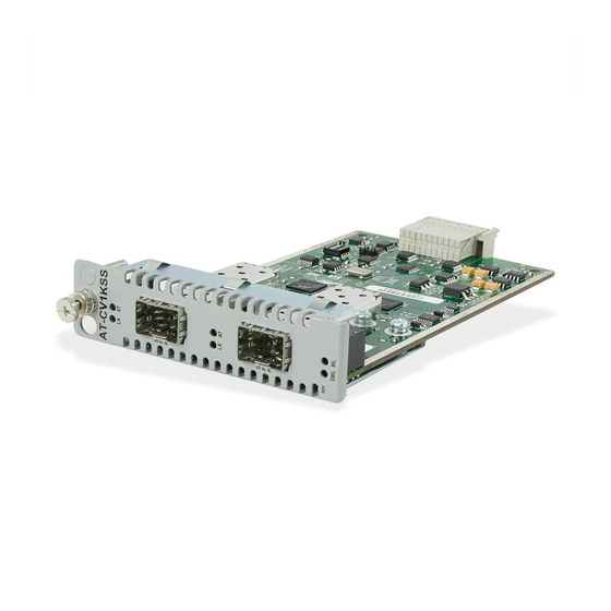
The AT-CV1KSS line card is a dual 1000Base-TX SFP line card. You can install this line
card in any Converteon Series chassis. The line card features two small form factor
pluggable (SFP) transceiver slots. The line card is hot-swappable into and out of a
Converteon chassis.
Related Documents
For details on the features and functions of a Converteon chassis, refer to the relevant
documents on our web site, www.alliedtelesis.com.
Verifying Package Contents
Ensure that the following items are included in your package:
One AT-CV1KSS line card
This installation guide
If any item is missing or damaged, contact your Allied Telesis sales representative for
assistance.
AT-CV1KSS Line Card Components
An AT-CV1KSS line card has the components shown below.
DIP Switches
A T- C
V 1K
S S
LK
AT
SFP Port LEDs
S
F
P
LK
AT
SFP Ports
S
F
P
RDY
Line Card Status LEDs
SM L
ML
SFP Ports Description
The SFP ports support an SFP transceiver with a fixed operating speed of 1000 Mbps.
LEDs
The AT-CV1KSS line card has three status LEDs and two LEDs for each SFP port, as
described in "LED Descriptions."
DIP Switches
One set of DIP switches allows you to set the operating mode, as described in "DIP Switch
Settings."
Installing an AT-CV1KSS Line Card
Note
Before you install an AT-CV1KSS line card, refer to the appropriate Converteon
chassis installation guide for electrical safety and emissions information.
Warning: Remove all metal jewelry, such as rings and watches, before installing
or removing a line card from a powered-on chassis.
Caution: Be sure to observe all standard electrostatic (ESD) precautions, such as
wearing an antistatic wrist strap, to avoid damaging the device. A line card can be
damaged by static electricity
Note
You can install a Converteon line card in any Converteon chassis line card slot.
To install an AT-CV1KSS line card, perform the following procedure:
1.
Remove the AT-CV1KSS line card from its shipping package and store the package
in a safe place. You must use the original package if you need to return the unit to
Allied Telesis.
2.
Configure the line card's DIP switches as required. Refer to "DIP Switch Settings" for
more information.
3.
Select any line card slot in the chassis where you want to install the AT-CV1KSS line
card, and remove the blank slot cover if one is installed.
4.
Align the back edge of the line card with the to and bottom alignment guides located
inside the slot.
5.
Slide the line card into the slot until the front of the card is flush with the front of the
chassis.
Note
Avoid touching the line card components.
6.
Secure the AT-CV1KSS line card to the chassis by using a Phillips screwdriver to
tighten the captive screw on the faceplate.
Note
Always tighten the captive screw to secure the line card to the chassis.
7.
Repeat this procedure to install additional AT-CV1KSS line cards.
559
1
LED Descriptions
Status LEDs
The line card has four status LEDs as described in the following table. For more information
about Smart MissingLink and MissingLink, refer to the relevant management software
user's guide.
LED
State
RDY
Green
The line card has passed diagnostics.
Off
The line card has not passed diagnostics.
SML
Green
The Smart MissingLink mode is enabled.
Off
The Smart MissingLink mode is disabled.
ML
Green
The MissingLink mode is enabled.
Off
The MissingLink mode is disabled.
SFP Port LEDs
Each SFP port has two LEDs, as described in the following table. For more information
about Smart MissingLink, refer to the relevant management software user's guide.
LED
State
LK
Green
A link has been established on the port.
Blinking
While in Smart MissingLink mode, a valid connection is established
Green
on the port while a link on the other port is lost.
Off
No link has been established on the port.
AT
Blinking
TX/RX activity has been detected on the port.
Green
Off
There is no TX/RX activity on the port.
DIP Switch Settings
The DIP switches described in the following table allow you to set the operating mode of
the line card. For information about the operating modes as well as Smart MissingLink
and MissingLink, refer to the relevant management software user's guide.
Operating Mode
DIP 1
Smart MissingLink (SML)
OFF
MissingLink (ML)
OFF
Link Test (default)
OFF
Manufacturing Defaults
OFF
"X" means that the DIP switch position can be ON or OFF.
Warranty Information
The AT-CV1KSS line card has a limited warranty of five years. Go to
www.alliedtelesis.com/warranty for the specific terms and conditions of the warranty and
for warranty registration.
2
Description
Description
DIP 2
DIP 3
DIP 4
ON
ON
X
OFF
ON
X
OFF
OFF
X
OFF
OFF
X
3
Advertisement

Related Manuals for Allied Telesis AT-CV1KSS


Summary of Contents for Allied Telesis AT-CV1KSS
- Page 1 Caution: Be sure to observe all standard electrostatic (ESD) precautions, such as The AT-CV1KSS line card is a dual 1000Base-TX SFP line card. You can install this line wearing an antistatic wrist strap, to avoid damaging the device. A line card can be Green The MissingLink mode is enabled.
- Page 2 Immunity EN55024 Electrical Safety UL60950 ( ), EN60950 (TUV), CSA22.2 No. 950 Copyright © 2007 Allied Telesis, Inc. All rights reserved. No part of this publication may be reproduced without prior written permission from Allied Telesis, Inc.
Need help?
Do you have a question about the AT-CV1KSS and is the answer not in the manual?
Questions and answers