Table of Contents
Advertisement
Advertisement
Table of Contents

Subscribe to Our Youtube Channel
Related Manuals for Icom IC-41S


Summary of Contents for Icom IC-41S
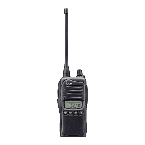
- Page 1 INSTRUCTION MANUAL UHF C.R.S.TRANSCEIVER i41S...
-
Page 2: Explict Definitions
‘overlap.’ Icom, Icom Inc. and the Icom logo are registered trademarks of Icom Incorporat- ed (Japan) in Japan, the United States, the United Kingdom, Germany, France,... -
Page 3: Precautions
Use and charge only specifi ed Icom bat- Exposing the inside of the transceiver to water will result in tery packs with Icom radios or Icom chargers. Only Icom bat- serious damage to the trans ceiver. tery packs are tested and approved for use with Icom radios... - Page 4 PRECAUTIONS BE CAREFUL! This device complies with Standard Aus- The transceiver will become hot when tralia Specifi cation No. AS/NZS 4365-2002 operating it continuously for long periods of time. and AS/NZS 4295: 2004. KEEP the transceiver away from the heavy rain, and Never immerse it in the water.
-
Page 5: Table Of Contents
TABLE OF CONTENTS ■ IMPORTANT ................i Priority Channel ...............10 EXPLICT DEFINITIONS ..............i To set the Priority Channel ..........10 GENERAL INFORMATION ............i To switch to the Priority Channel .........10 PRECAUTIONS ................ii To cancel the Priority Channel ........10 ■ TABLE OF CONTENTS ............. iv Monitor ................10 ■... -
Page 6: Table Of Contents
TABLE OF CONTENTS (Continued) 6 SCAN ................17–20 9 OTHER FUNCTIONS ............28–30 ■ Scanning Preparation ............17 Smart Ring/ATS ............28 Scan type selection .............17 RX Frequency ..............29 Tag Channel Setting ............17 PTT Hold ..............30 Scan Resume Condition ..........18 10 BATTERY CHARGING ..........31–35 ■... -
Page 7: Accessories
ACCESSORIES ■ Battery Pack Supplied Accessories To attach the battery pack: ➥ Slide the pack in the direction of the arrows (see below), Battery pack Battery charger AC adapter until the battery release button makes a ‘click’ sound. (for the battery charger) To release the battery pack: ➥... -
Page 8: D Belt Clip
ACCESSORIES Belt Clip Jack Cover q Attach the jack cover to the [MIC/SP] jack and tighten To attach the belt clip: Release the battery pack if it is attached as described at screws using a Phillips screwdriver. (see below) w To detach, unscrew using a Phillips screwdriver, and the left Slide the belt clip in the direction of the arrow (see below) remove to allow use of optional speaker-microphone or... -
Page 9: Unit Description
UNIT DESCRIPTION ■ e SIDE1 KEY [Side1] Front panel In Normal mode ➥ Push to toggle the monitor (open tone squelch) func- tion ON or OFF. (p. 10) ➥ Push and hold for 2 seconds to activate the following functions in order: Speaker •... - Page 10 UNIT DESCRIPTION i LCD DISPLAY (p. 6) !1 PRIO/SET.P KEY In Normal mode o SCAN/TAG KEY ➥ Push to change the selected channel to the priority In Normal mode channel. (p. 10) ➥ Push to start or stop scanning. This is dependent on ➥...
-
Page 11: Display
UNIT DESCRIPTION ■ Display t BELL INDICATOR ➥ Appears when the pocket beep function is in use. (p. 23) ➥ Blinks when the specifi ed selcall or smart ring call is received. (pp. 26, 28) y QUIET INDICATOR Appears when the quiet function is ON. (p. 27) u PRIORITY CHANNEL INDICATOR Appears when the priority channel is set. -
Page 12: Unit Description
UNIT DESCRIPTION !2 LOW POWER INDICATOR ➥ Appears when low output power is selected, or the unit is operating in dry (alkaline) battery mode. ➥ When the battery power decreases below the specifi ed level, the unit will switch to low power automatically. !3 OPEN SCAN INDICATOR Appears when open scan is selected. -
Page 13: Basic Operation
BASIC OPERATION ■ ■ Turning the Power ON Battery type Prior to using the transceiver for the fi rst time, the battery The transceiver can be used with the supplied Li-ion battery pack must be fully charged for optimum life and operation. pack or the optional battery case with third party AA batter- ies. -
Page 14: Backlight
UHF CB band also help to allow clear, uninter- To enter set mode, push and hold [Top] for 2 seconds, rupted communication. The IC-41S can access all 80 channels then release. on the UHF CB band, as well as designated repeater channels. -
Page 15: Receiving/Transmitting
BASIC OPERATION ■ • Transmit inhibit function – The transceiver will restrict Receiving/Transmitting transmission under the following conditions: - The channel is busy, or different CTCSS/DTCS code is NOTE: Transmitting without an antenna may damage the received. (depending on the transmission lockout function transceiver. -
Page 16: Priority Channel
BASIC OPERATION ■ ■ Priority Channel Monitor The priority channel allows the user to have quick access to a The monitor function opens the squelch or tone squelch, al- specifi c channel. Only one channel can be set as the Priority lowing weak signals to be received. -
Page 17: Set Mode
SET MODE The Set Mode allows the user to change various settings in When in the Set Mode: the transceiver to suit their operating requirements. Available Push [Top] to select the desired item. settings may differ, depending on the preprogramming of the Push [CH Up] or [CH Down] to adjust the setting. -
Page 18: D Squelch
SET MODE Squelch Auto Power OFF In order to receive signals clearly, the squelch level can be The transceiver can be set to automatically turn off after a set adjusted to suit the operating environment. This eliminates period of inactivity (i.e. no key has been pushed). This can be background noise when there are no signals present. -
Page 19: D Beep
SET MODE Beep Battery Voltage By default, confi rmation beep tones are turned on. This can The transceiver can be set to display the remaining battery be toggled ON or OFF by the set mode, for silent operation. charge for a 2 second period after being turned ON. Battery voltage Battery voltage ON Beep tone ON (default) -
Page 20: Dtot (Time-Out Timer)
SET MODE TOT (Time-Out Timer) Scan Resume Timer The time-out timer limits the length of one continuous trans- The scan resume condition can be set as a pause (P5) or mission. This helps conserve battery charge in the event of timer scan (15/10/5). -
Page 21: D Own Id
SET MODE Own ID This function allows the user to edit their own ID (this function is inactive by default, and can be turned on via dealer program- ming). Own ID is useful in commercial applications to allow organisations to track where transmissions originate from. To edit: When in set mode, and own ID has been selected, push and hold... -
Page 22: Repeater Operation
REPEATER OPERATION ■ Repeater Operation To access the repeater channels: Repeaters extend the operational range of the transceiver by ➥ Use the [CH Up] and [CH Down] keys to select a repeater amplifying received signals. They are usually located on the channel. -
Page 23: Scan
SCAN The IC-41S has four scan types, a tag function and four re- Tag Channel Setting sume conditions. Scanning allows the transceiver to automat- Setting channels as ‘tag’ channels allows them to be included in the scan function. ically scroll through all or selected channels in order to fi nd a transmission. -
Page 24: Scan Resume Condition
SCAN ■ Scan Resume Condition Open Scan The scan resume condition can be set as a pause (P5) or timer scan (15/10/5). When a signal disappears, scanning will The open scan function scans for transmitted signals, making resume after 5 seconds, regardless of the setting. it easier to locate new stations for contact or listening pur- poses. -
Page 25: Group And Priority Scan
SCAN ■ Group and Priority Scan Group and priority scans repeatedly watch a priority chan- Set the priority channel by pushing and holding nel while scanning the specifi ed tag channels. This is useful two seconds while on the desired channel. when waiting for a call on the priority channel. -
Page 26: Repeater
SCAN ■ Repeater search scan fl ow Repeater The repeater search scan is not only used to search for a sig- nal on the repeater channels, but also to access a repeater by Searches for sig- Scan start transmitting automatically in sequence. The repeater search Scan nal on the repeater channel... -
Page 27: Tone Squelch
The IC-41S is equipped with both CTCSS t Repeatedly push [CH Up] and [CH Down] to set the de- (Continuous Tone-Coded Squelch System) and DTCS (Digi- sired CTCSS tone frequency/DTCS code. - Page 28 TONE SQUELCH • Available CTCSS tone frequency list (Hz) • Available DTCS code list Code Code Code Code Code Freq. Freq. Freq. Freq. Freq. 67.0 94.8 136.5 177.3 218.1 69.3 97.4 141.3 179.9 225.7 71.0 100.0 146.2 183.5 229.1 71.9 103.5 151.4 186.2...
-
Page 29: Turning The Tone Squelch Operation On Or Off
TONE SQUELCH Turning the tone squelch operation Setting up and using the pocket Beep ON or Select the desired channel (excluding channel 5 or 35) Select the desired channel (excluding channel 5 or 35) us- using the [CH Up] and [CH Down] keys. ing the [CH Up] and [CH Down] keys. -
Page 30: Selcall (Selective Calling)
SELCALL (Selective Calling) In addition to tone squelch operation for silent stand-by, Sel- To select a TX code channel Call operation is available. In tone squelch operation, there Select the desired CB channel (CB-XX) except channels are 155 tone/code options when making a call. SelCall offers 5 and 35. -
Page 31: Dtx Code Number Edit
SELCALL (Selectyive Calling) TX code number edit u Repeat step t and y to input all digits. “ ” enables the user to change the TX code digits contained i After setting the fi nal digit, push to set the code and in the TX code channel. -
Page 32: Receiving
SELCALL (Selective Calling) ■ Receiving Receiving an individual call (default setting) Recalling a memorised receive selcall code ➥ “PiRo” beeps sound. Push [Top] to enter the function mode, then push and hold ➥ The received code channel name/number is displayed for 2 seconds to display the memorised RX code. -
Page 33: Quiet Mode
SELCALL (Selective Calling) ■ ■ Quiet Mode Stun ➥ When quiet mode is turned ON, selcall mute is activated and When a specifi ed ID, set as a kill ID, is received, the stun allows silent operation until a selcall code is received. Push function is activated (PC programming is required). -
Page 34: Other Functions
Icom unit is in range, which is useful in convoy situations rounding communication area. When an RX channel is where groups may be separated. -
Page 35: Rx Frequency
OTHER FUNCTIONS RX Frequency To program the RX frequencies: The frequency of the RX channels can be re-programmed Select the desired RX channel (RX-XX), once enabled. within the 450–520 MHz frequency range, to allow the trans- Push [Top] to enter function mode, then push and hold ceiver to listen to communications outside the standard CB [Top] for 2 seconds to enter the RX VFO mode. -
Page 36: Ptt Hold
OTHER FUNCTIONS D RX Frequency PTT Hold To program the RX frequencies: (Continued) The PTT switch can be operated as a one touch PTT switch (each push toggles between transmit/receive). Using this y Edit the disred digit with [CH Up] and [CH Down] function makes it possible to transmit without holding down the PTT switch. -
Page 37: Battery Charging
Icom radios or Icom chargers. Only Icom battery water, or any other liquids. Never charge or use a wet battery. packs are tested and approved for use and charge with Icom If the battery gets wet, be sure to wipe it dry before using. The radios or Icom chargers. -
Page 38: Charging Caution
CAUTION: NEVER charge the battery outside of the speci- perature environment (above +50˚C) for an extended period fi ed temperature range: BC-160 (0˚C to +40˚C). Icom recom- of time. If the battery must be left unused for a long time, it mends charging the battery at +20˚C. -
Page 39: Optional Battery Chargers
BATTERY CHARGING ■ Optional battery chargers Rapid charging with the BC-160 AD-106 installation The optional BC-160 provides rapid charging of the Li-ion The AD-106 must be installed into the BC- CHARGER ADAPTER battery packs. 119N or BC-121N before battery charging. Charging period: Approximately 3 hours (with BP-232N) q Connect the AD-106 The following items are additionally required:... -
Page 40: Rapid Charging With The Bc-119N+Ad-106
BATTERY CHARGING ■ Optional battery chargers (Continued) Rapid charging with the BC-119N+AD-106 Rapid charging with the BC-121N+AD-106 The optional BC-119N provides rapid charging of the Li-ion The optional BC-121N allows up to 6 battery packs to be battery pack. charged simultaneously. Charging period: Approximately 3 hours (with BP-232N) The following items are additionally required. -
Page 41: Battery Charging
BATTERY CHARGING IMPORTANT: Battery charging caution Ensure the guide tabs on the battery pack are correctly aligned with the guide rails inside the charger adapter. (This illustration is described with the BC-160) Tabs Guide rail... -
Page 42: Options
OPTIONS ■ Optional battery case (BP-240) When using the optional battery case, install 6 AAA (LR03) Fig.1 size alkaline batteries as illustrated at right. BP-240 q Unhook the battery cover release hook (q), and open the cover in the direction of the arrow (w). (Fig.1) w Then, install 6 ... -
Page 43: Contents
OPTIONS ■ r Clip the belt clip to a part of your belt. And insert the MB-93 contents transceiver into the belt clip until the base clip inserted Qty. fully into the groove. q Belt clip ……………………………………………………… 1 w Base clip …………………………………………………… 1 ■... -
Page 44: Detaching
OPTIONS ■ Detaching q Turn the transceiver upside down in the direction of the w Release the battery pack if it is attached. (p. 1) arrow and pull out from the belt clip. e Pinch the clip (q), and slide the base clip in the direction of the arrow (w). -
Page 45: Battery Pack
OPTIONS BATTERY PACK BELT CLIPS • MB-93 SWIVEL BELT CLIP Battery pack Voltage Capacity Battery life* • MB-94 BELT CLIP BP-232N 7.4 V 2000 mAh 13.5 hrs. Exclusive alligator-type belt clip. • MB-96N/96F LEATHER BELT HANGER Battery case for AAA BP-240 —* (LR03) ×... -
Page 46: Other Options
Aproved Icom optional equipment is designed for optimal per- formance when used with an Icom transceiver. Icom is not responsible for the destruction or damage to an Icom transceiver in the event the Icom transceiver is used with equipment that is not manufactured or approved by Icom. -
Page 47: Specifications
• External speaker connector • Power supply requirement : 7.2 V DC nominal* (negative ground) All stated specifications are subject to change without *Specifi ed Icom’s battery pack only notice or obligation. • Frequency stability : ±2.5 ppm (–30°C to + 60°C) : 50 Ω... -
Page 48: Warranty And Registration
Pty Ltd to an authorized Dealer of Icom (Australia) Pty. Ltd. quality of workmanship and components included in the production Please check with us if you feel an Icom product is being of every product. offered for sale that has been sourced from other than Icom (Australia) Pty. - Page 50 Purchasers Name: Purchasers Address: Email: Contact Phone No: Occupation: Answering the following question will better help us meet your future needs: In what media have you seen ICOM Advertising? Newspaper Magazine Radio Website Other: Magazines you regularly purchase and/or subscribe to:...
- Page 51 MEMO...
- Page 52 MEMO...
- Page 53 MEMO...
- Page 54 MEMO...
- Page 55 MEMO...
- Page 56 A-6944H-1AU Printed in Japan © 2011 Icom Inc. 1-1-32 Kamiminami, Hirano-ku, Osaka 547-0003, Japan Printed on recycled paper with soy ink.
Need help?
Do you have a question about the IC-41S and is the answer not in the manual?
Questions and answers