Table of Contents
Advertisement
Advertisement
Table of Contents

Subscribe to Our Youtube Channel
Related Manuals for Icom ic-450


Summary of Contents for Icom ic-450
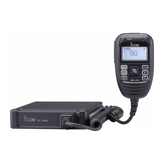
- Page 1 INSTRUCTION MANUAL UHF TRANSCEIVER i450...
-
Page 2: Explicit Definitions
The user of this UHF CB communications device shall not transmit Selcall tones for longer than 3 seconds Icom, Icom Inc. and Icom logo are registered trademarks of Icom Incorporated during any 60 second period. (Japan) in Japan, the United States, the United Kingdom, Germany, France,... -
Page 3: Precautions
OPERATIONAL NOTES PRECAUTIONS R WARNING! NEVER vii. UHF CB repeaters extend the operational range of connect the radio to an AC your radio. Repeaters operate utilising two channels outlet. This may pose a fire hazard or result in an electric shock. (repeater input/repeater output). - Page 4 If the radio becomes dusty or dirty, wipe it clean with a soft, dry cloth. This device complies with Standard Australia Specification No. AS/NZS 4365- Icom microphones only (supplied or optional). Other 2011. manufacturer’s microphones have different pin assignments and may damage the radio if attached.
-
Page 5: Table Of Contents
TABLE OF CONTENTS IMPORTANT ................i 4 SET MODE ..............16–19 EXPLICIT DEFINITIONS ............i Set mode ..............16 ■ SET mode items ............17 OPERATIONAL NOTES ............i ■ PRECAUTIONS ..............ii 5 REPEATER OPERATION ..........20 TABLE OF CONTENTS ............iv Repeater operation ............20 ■... -
Page 6: Table Of Contents
TABLE OF CONTENTS (Continued) 9 OTHER FUNCTIONS ..........32–34 Smart Ring and ATS ..........32 ■ RX frequency (for only RX channels) ......33 ■ Data cloning ...............34 ■ All reset ..............34 ■ 10 SPECIFICATIONS AND OPTIONS ......35–36 Specifications .............35 ■ Options ...............36 ■... -
Page 7: Accessories And Installation
ACCESSORIES AND INSTALLATION ■ Supplied accessories ■ Installation and Connection D Location q DC power cable (3 m) ····················································· 1 w Mounting bracket ···························································· 1 Select a location which can support the weight of the radio e Microphone (HM-212) ····················································· 1 and does not interfere with driving. -
Page 8: Installation Methods
Insert the mounting bracket’s rail to the transceiver’s slot, then slide the transceiver to attach to the mounting bracket. Flat washer < Sample 2: IC-450 is installed under the glove compartment Spring washer or on the center console.> Rail... -
Page 9: Microphone Hanger
ACCESSORIES AND INSTALLATION D Microphone Connect the supplied microphone as illustrated below. Release lever Microphone hanger NOTE Attach the supplied microphone hanger as illustrated below. • When detaching the transceiver from the mounting bracket, push up and hold the release lever, then pull the transceiver to the direction of the arrow. -
Page 10: Dc Power Supply
DC power cable through a metal plate to prevent a short circuit. • Connecting to a DC power source • Connecting to a DC power supply Grommet IC-450 IC-450 Optional speaker (SP-35) _ black... -
Page 11: Accessories And Installation
ACCESSORIES AND INSTALLATION D Antenna Antenna location • Antenna connector To obtain the transceiver's maximum performance, select The antenna with a PL-259 connector. a high-quality antenna and mount it in a good location. A non-radial antenna should be used when using a magnetic NOTE: mount. -
Page 12: Unit Description
UNIT DESCRIPTION ■ Front and rear panels w EXTERNAL SPEAKER JACK [SP] Connects a 4 Ω speaker. (p. 4) • Audio output power is typically 5 W. i450 e POWER RECEPTACLE A ccepts 13.8 V or 27.6 V DC with the supplied DC power cable. -
Page 13: Hm-212 Description
UNIT DESCRIPTION ■ HM-212 Description r D-PAD KEYS []/[]/[]/[]/[] Push [ ]/[] to select an operating channel, menu ➥ setting and so on. (pp. 10, 16) Microphone Push [ ]/[] to select a digit to edit. (pp. 29, 33) ➥ Push [ ] to select an item or setting in the menu. -
Page 14: Display
UNIT DESCRIPTION ■ Display t QUIET ICON (p. 31) q w ert Appears when the Quiet function is ON. (Selcall mute is activated) y TONE ICON (p. 26) ➥ “T” appears while the Subaudible tone encoder is used. “T SQL” appears while the Tone squelch/DTCS ➥... - Page 15 UNIT DESCRIPTION !2 PRIORITY CHANNEL ICON (p. 13) Appears when the Priority channel is set. !3 TAG CHANNEL ICON (p. 22) Appears when a Tag channel is selected.
-
Page 16: Basic Operation
BASIC OPERATION ■ Turning power ON ■ Adjusting the volume Hold down for 2 seconds to turn the power ON. Push to adjust the audio level. (0 to 32) If the transceiver is programmed with a start-up • “ ” appears when the audio level is set to 0 (silent mode). password, the screen as described below is displayed. -
Page 17: Receiving And Transmitting
BASIC OPERATION ■ Receiving and transmitting D Zone selection (Selectable only when more than two zones are set.) Receiving: Push to enter the menu mode. Hold down for 2 seconds to turn ON the power. Push [ ] or [] to select “Zone,” and then push [] to •... -
Page 18: Setting The Output Power Level
BASIC OPERATION D Transmitting notes Receiving and transmitting (Continued) ■ • Transmit inhibit function Transmitting: The transceiver has several inhibit functions that restrict Wait for the channel to become clear to avoid interference. transmissions under the following conditions: q Hold down [PTT] and speak at your normal voice level. - The channel is busy or a unmatched CTCSS/DTCS •... -
Page 19: Priority Channel
BASIC OPERATION ■ Priority channel D Canceling the Priority channel The Priority channel is simply recalled by momentarily Push [ ] to select the Priority channel. pushing [] in the operating mode. It is also automatically Hold down [ ] for 2 seconds to cancel the Priority monitored during a Group scan or Priority scan. -
Page 20: Monitor
BASIC OPERATION ■ Monitor ■ Adjusting the squelch level This function is used to listen to weak signals, or to manually Adjust the noise squelch level between 0 and 9. In order to open the tone squelch. receive signals properly, as well as for the scan to function ➥... -
Page 21: Backlight
BASIC OPERATION ■ Backlight ■ Voice recorder The transceiver has backlight modes for night-time and low- The transceiver has a voice recorder function for recording light operations. messages. You can turn the function ON in the set mode. The received message is automatically recorded and saved. (p. 19) Push to enter the menu mode, and then select D Recording a message... -
Page 22: Set Mode
SET MODE ■ Set mode D Set mode list In the Set mode, you can change various common settings for the transceiver, or individual settings for the operating Item Default Ref. channel. Essentially, you can customise the transceiver to • CTCSS/DTCS 01:67.0 (CTCSS) suit your preference and operating style. -
Page 23: Set Mode Items
SET MODE ■ SET mode items D Scan Resume D CTCSS/DTCS The Scan Resume can be set as a pause (5sec No Signal) or Select the desired CTCSS tone frequency or DTCS code. timer scan (5sec/10sec/15sec). When signal disappears, scan •... -
Page 24: Power Timer
SET MODE D Power Timer D Signal Indication This function turns OFF the transceiver when this set period The signal indication changes the transceiver’s display when of time has passed without a key operation. a Selcall code or roger beep is transmitted. “Roger Beep” Set the desired time to turn OFF the transceiver to between is displayed while transmitting a roger beep, and “Selcall”... -
Page 25: Set Mode
SET MODE Backlight D Noise Cancel You can change the backlight modes for night-time and low- This function allows clear communication by reducing the light operations. Select the desired mode. (Default: ON) surrounding noise, especially the low frequency noise received by the microphone. Turn the function ON or OFF. •... -
Page 26: Repeater Operation
REPEATER OPERATION ■ Repeater operation D Accessing a repeater Repeaters extend the operational range of the transceiver A repeater amplifies received signals, and retransmits them by retransmitting the received signals. They are usually on a different frequency, allowing you to communicate located on the top of a building or a mountain, as the over greater distances with improved reliability. -
Page 27: Scan
SCAN ■ Scan types Tag channels are independently set for Open, Group and The transceiver has 4 scan types, a Tag function and 4 Priority scans. All channels may be preset as tag channels Resume options, for scanning versatility. for all scans. OPEN SCAN �... -
Page 28: Scanning Preparation
The IC-450 scans all tagged channels when a scan is activated. D Tag channel setting When the IC-450 finds a busy channel, it can be set to pause, or Before setting the tag channels, you must select the desired to resume after a pause. (Except for the Repeater search scan). -
Page 29: Open Scan
SCAN ■ Open scan D Scan resume mode An Open scan automatically searches for transmitted signals and enables you to locate new stations for Push to enter the menu mode. communication or listening. Push [ ] or [] to select “Scan Resume.” (“Settings”... -
Page 30: Group Scan And Priority Scan
SCAN ■ Group scan and priority scan Push to start the scan. Group and priority scans repeatedly look for a signal on the priority channel while scanning the specified channels. This Group scan Priority scan is useful when waiting for a call on the priority channel or Blinks Blinks several specified channels. -
Page 31: Repeater Search Scan
SCAN ■ Repeater search scan D Repeater search scan The Repeater search scan is used not only to search for a signal on the repeater channels, but also to access a repeater by automatically transmitting in sequence. The Searches for signals on the re- Repeater search function detects repeaters that can be Scan peater output channels. -
Page 32: Tone Squelch And Pocket Beep
TONE SQUELCH AND POCKET BEEP ■ Tone squelch The transceiver is equipped with 51 CTCSS tone CTCSS tone DTCS code frequencies, and 104 DTCS codes. CTCSS/DTCS operation enables you to communicate in the silent standby mode, since you will only receive calls from group members using the same CTCSS tone frequency or DTCS code. -
Page 33: Pocket Beep
TONE SQUELCH AND POCKET BEEP ■ Pocket beep • Selectable CTCSS tone frequency list (Hz) This function uses the CTCSS (subaudible) tone and the Freq. Freq. Freq. Freq. Freq. DTCS code for calling, and you can use it as a “common 67.0 94.8 136.5... -
Page 34: Selcall (Selective Calling)
TX code is a Selcall code that you can transmit. A maximum when using 5 tone. of 32 TX code channels can be entered into the IC-450, using the optional CS-450 Other options in Selcall are for calling another unit or Group... -
Page 35: Tx Code Edit
SELCALL (Selective Calling) D TX code edit NOTE: The TX code’s editable digits can only be set, or You can change the TX code contents within the allowed changed using the CS-450 cloning software digits. The Group call function enables you to edit a special ‘Group code’... -
Page 36: Receiving
SELCALL (Selective Calling) ■ Receiving D Recalling a memorised received ID code D Receiving an individual call Push to enter the menu mode. When receiving an RX code (default setting): Push [ ] or [] to select “History” to display the •... -
Page 37: Selcall (Selective Calling)
SELCALL (Selective Calling) ■ Quiet mode To enable Selcall mute: When the Quiet mode is turned ON, the Selcall mute is While the TX/RX indicator blinks, hold down for 2 activated and allows Silent operation until receiving a Selcall. seconds to mute the channel. The TX/RX indicator stops blinking. -
Page 38: Other Functions
OTHER FUNCTIONS Smart Ring and ATS ■ (Automatic Transponder System) These functions have an answer back feature and NOTE: • The setting to the left is for only the calling station. A called confirmation function for when a call has reached the station automatically sends an answer back signal without any called station, even if the user is temporarily away from the presetting. -
Page 39: Rx Frequency (For Only Rx Channels)
OTHER FUNCTIONS ■ RX frequency (for RX only channels) D RX frequency setting The RX channel frequency can be set to between 450 and 520 MHz. Push [] or [] to select the desired RX channel. D RX channel setting The RX channels are set to “Disable,”... -
Page 40: Other Functions
Resetting the transceiver sets all values to their defaults. While holding down , and , hold down ➥ IC-450 2 seconds to turn ON the transceiver power. • Resets the CPU. • “All Reset” appears on the function display. to a USB port... -
Page 41: Specifications And Options
SPECIFICATIONS AND OPTIONS ■ Specifications General Transmitter • Frequency coverage • Output power: 5 W/1 W (selectable) 476.425–477.4125 MHz • Modulation system: Variable reactance frequency modulation 450.000–520.000 MHz (RX only) • Max. frequency deviation: ±2.5 kHz • Mode: 8K50F3E • Frequency error: ±2.5 ppm •... -
Page 42: Options
SPECIFICATIONS AND OPTIONS ■ Options Specifications ■ Receiver (Continued) [RX (450.000–520.000 MHz)] (Except CB (476.425–477.4125 Microphone MHz)) • HM-212 hand microphone • Sensitivity (12 dB SINAD): 0.25 µV typical Wired remote control microphone with key backlight. The same • Hum and noise: 45 dB typical microphone that is supplied with the transceiver. -
Page 43: Maintenance
MAINTENANCE ■ Troubleshooting If your transceiver seems to be malfunctioning, please check the following points before sending it to a service center. PROBLEM POSSIBLE CAUSE SOLUTION REF. — The transceiver’s power • Power connector has poor contact. • Check the connector pins. p. -
Page 44: Maintenance
MAINTENANCE Troubleshooting (Continued) ■ PROBLEM POSSIBLE CAUSE SOLUTION REF. p. 18 Transmission continues • PTT Hold function is activated. • Turn OFF the function. even when the PTT is released. p. 34 The function display • The CPU is malfunctioning. •... -
Page 45: Warranty And Registration
(i.e. battery, antenna, battery chargers etc) ranty claim. Icom (Australia) Pty. Ltd. will, at its discretion, and subject to the terms and If the requested repairs or services are within the terms of warranty, conditions stated below, repair or replace any goods or component parts your equipment will be returned after repair (prepaid) to any desig- which after examination are found to be defective. - Page 48 P/Code : Purchasers Address: Email: Phone No: Occupation: Answering the following question will help us to meet your future needs: In what media have you seen Icom products advertised? Other: Newspaper Magazine Radio Website Magazines you regularly purchase from the Newsagent:...
- Page 49 MEMO...
- Page 50 MEMO...
- Page 51 MEMO...
- Page 52 MEMO...
-
Page 53: Index
INDEX – A – – G – Accessing a repeater ............20 Group scan and priority scan ..........24 Adjusting the squelch level ..........14 – H – Adjusting the volume ............10 All reset ................34 HM-212 Description ..............7 Antenna ................5 ................32 – I – –... - Page 54 INDEX – O – – S – Open scan ................23 Scanning preparation ............22 OPERATIONAL NOTES ............i Scan Restart ...............17 Options ................36 Scan Resume ..............17 Scan resume mode ............23 – P – Scan types ................21 Selecting a channel ............10 Playing the recorded message ...........15 Selecting the scan mode ............22 Pocket beep ................27 Set mode ................16...
- Page 55 INDEX – U – Using the mounting bracket ..........2 – V – Voice Guidance ..............18 Voice Recorder .............15, 19 – W – Waiting for a call from a specific station ......27 – Z – Zone selection ..............11...
- Page 56 A-7218D-1AU Printed in Japan © 2015 Icom Inc. 1-1-32 Kamiminami, Hirano-ku, Osaka 547-0003, Japan Printed on recycled paper with soy ink.
Need help?
Do you have a question about the ic-450 and is the answer not in the manual?
Questions and answers