Table of Contents
Advertisement
Advertisement
Table of Contents

Subscribe to Our Youtube Channel
Related Manuals for ALLEN & HEATH XONE V6


Summary of Contents for ALLEN & HEATH XONE V6
- Page 1 ALLEN&HEATH User Guide Publication AP4975...
- Page 2 XONE:V6 User Guide AP4975 Issue 2 Copyright © 2003 Allen & Heath Limited. All rights reserved Whilst we believe the information in this guide to be reliable we do not assume responsibility for inaccuracies. We also reserve the right to make changes in the interest of further product development. This product complies with the European Electromagnetic Compatibility directives 89/336/EEC &...
-
Page 3: Important Safety Instructions
Important Safety Instructions – Read First Read instructions: Read and retain these instructions for future reference. Read the instructions on the Safety Sheet provided separately. Adhere to all warnings printed here and on the console and its power unit. Covers: Do not remove the power unit cover. - Page 4 Important Note on Mains Voltage Setting The power unit has two mains voltage settings. Check that your unit is correctly set to work with your local mains voltage. This is marked on the power unit rear panel. The setting cannot be changed by the user.
-
Page 5: Table Of Contents
Contents Important Safety Instructions .............3 Front and Rear Panel Drawings ..........6 Welcome to the XONE:V6............7 Front Panel Controls ..............8 Rear Connectors ..............14 Installing the Power Supply............21 Installing the Console...............23 Grounding ................24 Wiring the Cables ..............26 Connector Types..............27 Switching the Console On............28 Operating Level and Meters .............29 Internal Option Jumpers............30 Replacing the VU Meter Bulb ...........34... -
Page 6: Front And Rear Panel Drawings
LEFT MIX LEVEL RIGHT MIX LEVEL INPUT 1 INPUT 2 INPUT 3 INPUT 4 INPUT 5 INPUT 6 LINE LINE LINE LINE LINE B LINE B PHONO PHONO PHONO PHONO LINE A LINE A LEVEL LEVEL LEVEL LEVEL LEVEL LEVEL 10kHz 2.5kHz 10kHz... -
Page 7: Welcome To The Xone:v6
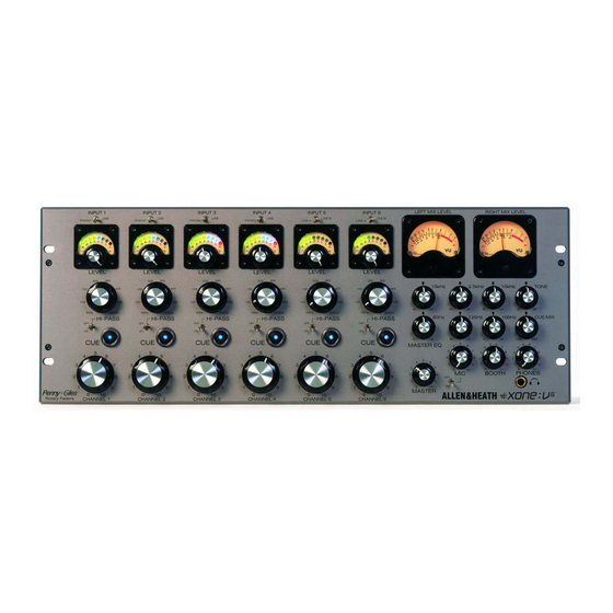
Welcome to the The XONE:V6 is an audiophile rotary club mixer that sets a new The XONE:V6 also features the best in modern technology and quality benchmark. It is an echo of the earliest days of pro audio engineering excellence. The top of the range, oil damped rotary when pioneering individuals hand crafted outstanding products faders are made by Penny &... -
Page 8: Front Panel Controls
Channel Controls INPUT 4 LINE PHONO 6 Input channels are provided. Each has switchable inputs for two stereo sources. CH1-4 provide line and phono (RIAA) inputs. CH5 and 6 feature valve preamps and have two switchable line sources each. All channels provide insert points for patching in additional equipment. - Page 9 INPUT 5 Level LINE B Adjusts the input sensitivity from fully off to its maximum +10dB gain. LINE A Correct use of this control makes it impossible to overload the input preamp. Adjust it so that the meter averages around ‘0’ with loudest peaks up to ‘+6’. Note that there are internal option jumpers to reduce the maximum gain available to +6 or 0dB.
-
Page 10: Microphone Controls
Microphone Controls A DJ microphone can be plugged in. A professional quality balanced dynamic vocal type is recommended. Phantom power can be internally enabled if a condenser type is preferred. The mic can be switched into the master mix, booth mix, and routes to the cue monitor. An insert is available for patching in processors such as a limiter or compressor. - Page 11 Master Controls LEFT MIX LEVEL The Master is the main output that feeds the house sound system. An overall level control together with 2-band equaliser is provided. External processing equipment such as a limiter or house EQ can be inserted into the master mix signal path.
- Page 12 Booth Controls The DJ’s local loudspeakers are fed from the console BOOTH output. The booth mix is sourced from the master mix. It is derived post insert so that the DJ hears exactly what is being fed to the house system. The DJ microphone signal can be included or removed from the booth mix.
- Page 13 Headphones Controls The DJ headphones is sourced from the booth mix and switched cue system. Headphone sockets are provided on both the front and rear panels. Tone control This combines the LF and HF equaliser into one, easy to use TONE control.
-
Page 14: Rear Connectors
Channel Connectors Each channel has two stereo inputs. CH1-4 provide line and RIAA inputs. CH5 and 6 provide two line inputs. PHONO/ LINE LINE L and R inputs RCA phono sockets. The PHONO input provides gain and RIAA equalisation for turntable cartridges. Note that CH1-4 have internal option jumpers to disable RIAA if you want to use the inputs for additional line sources. - Page 15 Microphone Connectors The microphone input is used for the DJ microphone. A hi-pass filter is built in to reduce low frequency handling noise, popping and proximity effect. An MIC INPUT insert point is provided for patching in processors such as a compressor. Mic input Balanced XLR, pin 2 hot.
- Page 16 Master Connectors MASTER INSERT The master mix to feed the house system is available on two pairs of sockets, XLR and TRS. A pre-EQ insert point is provided for patching in processors such as house equaliser and protection limiter. Insert Unbalanced TRS (stereo) jack wired tip = send, ring = return, sleeve = common ground.
- Page 17 Booth and Record Connectors The XLR booth output feeds the DJ’s booth amplifier / loudspeaker system. The record output can be used to make a stereo recording of the performance. RECORD -10dBV Booth output Balanced XLR wired pin 2 hot. Output level is +10dBu when the BOOTH level control is fully clockwise and the VU meters read ‘0’.
- Page 18 Cue, Ground and Headphones Connectors EXT CUE INPUT External cue input TRS jack break point for overriding the cue system with an external audio signal. The input is unbalanced with tip = left, ring = right and sleeve = common ground. Cue DC link 9-pin D connector for linking the console cue logic system with external Allen &...
- Page 19 Power Supply Connector DC POWER INPUT ONLY USE CORRECT DC power input A heavy duty multi-pin socket for connection to the ALLEN&HEATH PSU external power unit using the DC cable provided. This carries the audio and logic regulated DC power rails required for console operation. Align the orientation lug and press the plug in.
- Page 20 Check mains voltage setting MAINS INPUT V.AC 47-63 Hz ~120W MAX FUSE 250V S/No MADE IN ENGLAND BY ALLEN & HEATH LIMITED air flow Mains lead This way up CAUTION: FOR CONTINUED PROTECTION AGAINST RISK OF FIRE REPLACE FUSE WITH SAME TYPE AND RATING. DISCONNECT SUPPLY BEFORE CHANGING FUSE. CAUTION ATTENTION: REMPLACER LE FUSIBLE AVEC UN DES MEMES CARACTERISTIQUES.
-
Page 21: Installing The Power Supply
Installing the Power Supply Unit A separate high performance mains power unit is provided. This To avoid damage to the power supply unit converts the mains voltage into the various DC power rails internal assemblies do not mount it on to any required by the console. - Page 22 483mm (19") 101.6mm (4") 76mm (3") 178mm (7") 4x M6 rack bolts 181mm (7 1/8") 441mm (17 3/8") 256mm (10") Allow 75mm (3") min clearance for connectors XONE:V6 User Guide...
-
Page 23: Installing The Console
Installing the Console Rack mount The console fits into a standard 19” rack system taking up 4U height. Use 4x M6 bolts with plastic protective cups. 441mm (17 3/8") These are usually supplied by the rack manufacturer. Plinth mount The console can be mounted in a custom built plinth or other furniture. -
Page 24: Grounding
Grounding The connection to ground (earth) in an audio system is important for two reasons: • SAFETY - To protect the operator from high voltage electric shock, and • AUDIO PERFORMANCE - To minimise the effect of ground loops which result in audible hum and buzz, and to shield the audio signals from interference pickup. - Page 25 To ensure safe and trouble-free operation we recommend the following: • Have your mains system checked by a qualified electrician If the supply grounding is solid to start with you are less likely to experience problems. • Do not remove the ground connection from the power unit mains plug The console chassis is connected to mains ground through the power cable to ensure your safety.
-
Page 26: Wiring The Cables
Wiring the Cables XONE:V6 User Guide... -
Page 27: Connector Types
Connector Types The XONE:V6 uses professional grade 3 pin XLR, 1/4" TRS jack and RCA PHONO sockets. The XLR connection should be used with balanced equipment such as microphones and feeds to balanced signal processors and amplifiers. This has 3 connector pins: Pin 1 = ground (screen), Pin 2 = signal hot (+), Pin 3 = signal cold (-). -
Page 28: Switching The Console On
Switching the Console On The XONE:V6 power unit has two mains voltage settings, 115- 230V and 100V AC. First check that the setting is correct for your local mains voltage. This is marked on the power unit rear panel. The 115-230V setting senses the mains voltage level within the MAINS INPUT V.AC 115 to 230V range and automatically configures the power circuit... -
Page 29: Operating Level And Meters
Operating Levels and Meters It is most important that the system level settings are correctly set. The best performance can only be achieved if the system levels are set within the normal operating range and not allowed to peak. Peaking simply results in signal distortion, not more volume. -
Page 30: Internal Option Jumpers
Internal Option Jumpers The XONE:V6 provides several user accessible internal jumper options. These are for specialist application or user preference and should not normally be needed. The factory default settings should satisfy most applications. The jumpers are plug-on and can be reconfigured quickly. - Page 31 Input Channel Option Jumpers Plug on jumpers set the options required. Plug across the two pins to set. Plug on to just one pin to remove. This keeps the jumper available to be re-used later in the future if needed. +10, +6, 0dB GAIN RIAA / LINE RIAA disable...
- Page 32 Microphone Option Jumper A plug on jumper sets the option required. Plug across the two pins to set. Plug on to just one pin to remove. This keeps the jumper available to be re-used later in the future if needed. Phantom power 30V phantom power is disabled when JP1 is fitted.
- Page 33 Master Option Jumpers Plug on jumpers set the options required. Plug across the two pins to set. Plug on to just one pin to remove. This keeps the jumper available to be re-used later in the future if needed. Master output level The output level with MASTER control at maximum position and VU meters reading ‘0’...
-
Page 34: Replacing The Vu Meter Bulb
VU Meter Bulb Replacement Each VU meter is illuminated using a filament bulb mounted in a clip behind the meter. The bulb is a long life type. If it needs to be replaced procede as follows: Unplug the cables and remove the console cover as described previously. -
Page 35: Block Diagram
System Block Diagram BLOCK DIAGRAM REMOVE LINKS FOR 0dBu OUT L INSERT MASTER EQ MASTER LEVEL 10kHz CHANNEL 1-4 R INSERT MASTER OUT MASTER MIX 80Hz LINKS SHOWN FITTED FOR RIAA HI PASS ROTARY FADER LEVEL FILTER INSERT PHONO ON/OFF RIAA SELECT 30Hz... -
Page 36: Technical Specification
Technical Specification CH1-6 Line Inputs Master Output RCA L and R connectors Balanced XLR (for balanced connection only) Level variable from off to +10dB gain (+6, 0dB options) TRS jack (for unbalanced connection) Impedance >10k ohm XLR operating level +4dBu (0dBu option) TRS operating level -2dBu CH1-4 RIAA Inputs Impedance <110 ohm... -
Page 37: Headphones Output
Headphones Output Frequency response TRS jack Tip = L, Ring = R Line in to Master out +0/-0.5dB 10Hz to 30kHz 30 to 600 ohms headphones, 70 ohms recommended +0/-1dB 8Hz to 40kHz Power 480mW into 70 ohms, 150mW into 600 ohms Maximum Output Level Channel Hi-Pass Filter Master output... -
Page 38: Power Supply
Noise Power Supply Measured 22Hz to 22kHz Master XLR output <-100dBu residual External unit with detachable DC cable <-90dBu @ unity gain Vertical mount with fixing brackets Master TRS output <-105dBu residual Hybrid linear design <-97dBu @ unity gain Switched mode for mains voltage sensing Booth output <-96dBu residual Linear design for voltage rails... -
Page 39: Performance Curves
Channel Hi-Pass filter Microphone EQ This graph shows the This graph shows the response of response of the filter at its minimum (30Hz) and maximum the equaliser at maximum LF and HF boost and cut. The (600Hz) settings. The curve can be swept between these shelves are tuned for vocal equalisation at 120Hz (LF) and positions. - Page 40 RIAA Valve channel distortion This graph shows the equalisation curve of the This graph shows the channel RIAA input. This compensates for the response of harmonic distortion associated with the valve preamp. The the pickup cartridge to result in a flat music response. 1kHz test tone is shown, together with a strong second harmonic distortion.
-
Page 41: Phones
Master and Booth EQ Headphones EQ This graph shows the This graph shows the response of response of the master equaliser at maximum cut and the equaliser at maximum TONE control positions. Fully boost. It has 80Hz (LF) and 10kHz (HF) shelves with up to anti-clockwise LF is boosted by 6dB and HF cut by 12dB. -
Page 42: User Notes (Blank Page)
User Notes: XONE:V6 User Guide...
Need help?
Do you have a question about the XONE V6 and is the answer not in the manual?
Questions and answers