Advertisement
Advertisement
Table of Contents

Related Manuals for ALLEN & HEATH GL2


Summary of Contents for ALLEN & HEATH GL2
-
Page 3: Service And Technical Support
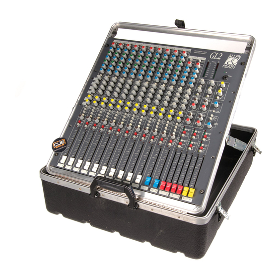
This user guide presents a quick reference to the function, application and installation of the GL2. For further information on the basic principles of audio system engineering please refer to one of the specialist publications available from bookshops and audio equipment dealers. - Page 4 THE GL2 The ALLEN & HEATH GL2 offers the flexible solution to the many requirements of the live sound and recording environment; whether for conference sound ... in a club ... theatre .. or church ... for touring ... contract hire ... as well as stereo and multitrack recording.
-
Page 5: Specification
SPECIFICATION 0 dBu = 0.775 Volts RMS 0 dBV = 1 Volt RMS INTERNAL OPERATING LEVEL: -2 dBu FREQUENCY RESPONSE: 20Hz to 20kHz +0/-1dB INTERNAL HEADROOM: .... +23 dB MAX OUTPUTS: ......balanced +27 dBu 600 ohms max load DISTORTION: . THD 0.01% Line in to mix out at 1kHz unbalanced +21 dBu 2kohms max load All console inputs and outputs are in-phase except for the GROUP INSERTS... -
Page 6: Installing The Console
INSTALLING THE CONSOLE The GL2 fits into an 11U space in a standard 19" rack system. Alternatively the console may be adapted for plinth or table top operation. Provide adequate space behind the rear of 19" rack width the console power unit for ventilation. -
Page 7: Adjusting The Levels
Check the cables for correct wiring to avoid problems with phase reversal and unreliable connection. The GL2 follows the convention for XLR pin 2 and jack tip = signal hot (+). Always use balanced cables when connecting to phantom powered microphones. -
Page 8: Checking The Signal
INPUT MATCHING THE INPUT PRECAUTION ! A wide-ranging padless input pre-amplifier matches the ALWAYS MAKE SURE THAT +48V SWITCHES ARE OFF connected audio source to the console. Use the PFL system (UP POSITION) WHEN THE CHANNEL INPUT XLRS ARE to set GAIN for the correct internal operating level (0dB CONNECTED TO NON-PHANTOM POWERED OR LINE SOURCES. -
Page 9: Dual Input
STEREO MATCHING THE INPUT INPUT A set the IN A/B switch up. INPUT B set the IN A/B switch down. MONO combines the left and right inputs to mono the source, or may be used to input a mono source to the stereo channel path. -
Page 10: Operating Mode
It is advisable to study the GL2 system block diagram to fully understand this flexible routing arrangement. RETURN/SUBGROUP... -
Page 11: Monitoring The System
MASTER MONITORING THE SYSTEM The PHONES/MONITOR section allows the engineer to listen to L-R (aux 5-6) either PRE or POST the master faders, or 2-TRACK return through up to two pairs of stereo headphones or monitor speaker systems while displaying the selected source on the L and R monitor meters. - Page 12 FRONT-OF-HOUSE MONO conference ... club ... disco ... live shows ... theatre ... church ... touring ... RIGHT LEFT FOLDBACK pre-fade aux sends EFFECTS groups insert sends returns COMPRESSOR/LIMITERS These are often used to prevent excessive peaks overloading the amplification system, for example in club installations subject to sound level control.
- Page 13 ON-STAGE MONITOR On-stage mixing system for local control of performers monitor loudspeakers (wedges) With dedicated output for the stage engineers wedge loudspeaker. STAGE MONITORS AMPLIFIERS splitter ENGINEERS WEDGE MONITOR Set up the WEDGE MIX by selecting one or a combination of the group/L/R AFL (monitor 1 to 6) switches to listen to the desired stage monitor outputs.
-
Page 14: Multi Mode
This example shows the GL2 configured to control a Left, Centre, Right Front-of House These switches system with 4 full feature stage monitor... - Page 15 RECORDING stereo and multitrack ... studio ... live ... location ... audio visual ... production ... stereo amplifier LEFT RIGHT MUSICIANS CUE MONITOR LOUDSPEAKER SYSTEM stereo amplifier outputs inputs Y-splitters (or repatch leads as required) 4-TRACK MULTITRACK line ins groups returns 2-TRACK RECORDER send...
Need help?
Do you have a question about the GL2 and is the answer not in the manual?
Questions and answers