Table of Contents
Advertisement
Advertisement
Table of Contents

Related Manuals for Chauvet Intimidator Spot 250


Summary of Contents for Chauvet Intimidator Spot 250
-
Page 1: User Manual
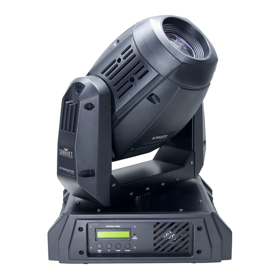
Snapshot Intimidator™ Spot 250 OK on Dimmer Outdoor OK Sound Activated DMX512 Master/Slave 115V/230V Switch Replaceable Fuse User Serviceable Duty Cycle USER MANUAL 3000 N 29 Ct, Hollywood, FL 33020 U.S.A. (800) 762-1084 – (954) 929-1115 FAX (954) 929-5560 www.chauvetlighting.com... -
Page 2: Table Of Contents
DMX Channel Values .................................. 22 5. Appendix ....................................26 DMX Primer ....................................26 Setting the starting address ................................. 26 Intimidator Spot 250 Service Maintenance Guide ........................27 Contact Us ....................................28 General Maintenance .................................. 28 Returns Procedure ..................................29 Claims ......................................29 Blow-out Diagram. -
Page 3: Before You Begin
1. B EFORE EGIN What is included 1 x Intimidator™ Spot 250 1 x Mounting bracket kit w/screws 1 x Power Cord 1 x Warranty Card 1 x User Manual Unpacking Instructions Immediately upon receiving a fixture, carefully unpack the carton, check the contents to ensure that all parts are present, and have been received in good condition. -
Page 4: Safety Instructions
There are no user serviceable parts inside the unit. Do not open the housing or attempt any repairs yourself. In the unlikely event your unit may require service, please contact CHAUVET at: 954-929-1115. Intimidator™ Spot 250 User Manual 8/24/2009 3:19 PM... -
Page 5: Introduction
2. I NTRODUCTION Features 10 or 14-channel DMX-512 moving yoke Pan: 540° / tilt: 270° Color wheel 7 interchangeable, slot-n-lock colors + white Split colors Rainbow color spin at variable speeds Indexed rotating gobo wheel with Gobo Bounce™ 7 interchangeable, slot-n-lock gobos + open 5 metal, 2 glass installed Rotating gobo wheel spin at variable speeds 3-facet, high-speed rotating prism at variable speeds... -
Page 6: Dmx Channel Summary
DMX Channel Summary Advanced Mode Basic Mode HANNEL UNCTION HANNEL UNCTION Pan coarse Tilt Tilt coarse Color Pan fine Gobo Tilt fine Gobo rotation Pan/Tilt speed Shutter Color Dimmer Gobo Effect Gobo rotation Prism Shutter Focus Dimmer Mode/function Effect Prism Focus Intimidator™... -
Page 7: Product Overview
Product Overview 115/230V switch Power switch DMX out Easy 3 & 5-pin Controller DMX in 3 & 5-pin Microphone IEC Power input Product Dimensions Intimidator™ Spot 250 User Manual 8/24/2009 3:19 PM... -
Page 8: Setup
3. S ETUP Lamp You will need to install a lamp prior to the initial operation of the fixture. A 250W MSD discharge lamp is included. Warning! When replacing the lamp, please wait 15 minutes after powering down to allow the unit to cool down! Always disconnect from main power prior to lamp replacement. -
Page 9: Lamp Installation
Lamp Installation Turn off power to fixture. Loosen the 2 lamp covers knobs by turning counter-clockwise. If there is a current lamp you are replacing, remove it now. While using care not to allow the envelope of the lamp to contact your bare skin, install the new lamp. -
Page 10: Fuse Replacement
Disconnect the power cord before replacing a fuse and always replace with the same type fuse. Fuse Replacement With a flat head screwdriver wedge the fuse The fuse is located holder out of its housing. Remove the damaged inside this fuse from its holder and replace with exact compartment. -
Page 11: Replacing Color Dichroics
Replacing Color Dichroics Top cover screws Be sure the fixture is not powered or connected to mains. Remove the top cover by removing the 4 screws with a Phillips #2 screwdriver. With your hand, move the color wheel to the desired color dichroic to change. Remove the slot-n-lock color by pressing it up and away from the color wheel and sliding in the direction out of the fixture. -
Page 12: Fixture Linking
Maximum recommended number of fixtures on a serial data link: 32 fixtures Data Cabling To link fixtures together you must obtain data cables. You can purchase CHAUVET-certified DMX cables directly from a dealer/distributor or construct your own cable. If you choose to create your own cable please use data-grade cables that can carry a high quality signal and are less prone to electromagnetic interference. -
Page 13: 3-Pin To 5-Pin Conversion Chart
If you use a controller with a 5 pin DMX output connector, you will need to use a 5 pin to 3 pin adapter. Note! CHAUVET Model No: DMX5M, or DMX5F. The chart below details a proper cable conversion: IN TO... -
Page 14: Mounting
Mounting O ri ent at ion This fixture may be mounted in a vertical-hanging or in a floor-mounting-vertical position, provided there is adequate room for ventilation. Rigg ing Hanging Clamp It is important never to obstruct the fan or vents pathway. Mount the fixture using, a suitable “C”... -
Page 15: Pan/Tilt Lock
P an/t ilt Lo c k This fixture has locking Pan/Tilt function. This is a feature designed to be used during transportation. Follow the below instructions for operating this properly. These steps are for the Pan Lock. Locate the Pan Lock on the base of the yoke. Using your hand (not a tool!) rotate this either clockwise or counter-clockwise 90°... -
Page 16: Operating Instructions
4. O PERATING NSTRUCTIONS Navigating the Control Panel Access control panel functions using the four panel buttons located directly underneath the LCD Display. Button Function Used to access the menu or to return to a <MODE/ESC> previous menu option Scrolls through menu options in ascending <UP>... -
Page 17: Menu Map
Menu Map UNCTION UNCTION ELECTION NSTRUCTION 1. DMX Address Address 000 ~ 255 Sets the DMX starting address Fast Sets the fixture to fast Auto mode Slow Sets the fixture to slow Auto mode Sets the fixture to audio triggering Auto Sound mode 2. -
Page 18: Menu Map (Continued)
Menu Map (continued) Service Menu Map The password is: 2323 Exit this mode by pressing Mode/Esc 2 times (2X) Intimidator™ Spot 250 User Manual 8/24/2009 3:19 PM... -
Page 19: User Configurations
User Configurations T o set th e pa n to i nv er tin g o r non - inv e rt i ng: Press the <MENU/ESC>. Select the desired option by using the <UP> and/or <DOWN> button to navigate through the display until you reach “3-Pan”. -
Page 20: Additional Functions
Additional Functions T o us e th e fi xtu r e w it h th e c a - 9 ea s y cont r oll e r. Under the “Run” option in the menu, select “Econtr”. Press the <ENTER> button. Now, plug in the CA-9 into the EASY CONTROLLER connection on the back panel of the fixture. -
Page 21: Operation
Operation Stand-Alone Mode (Sound-Active, Auto Mode): This mode allows a single unit to run to the beat of the music, or the unit will auto change in Auto Mode. Set the fixture to the desired standalone mode by selecting it in the onboard menu. Press <MENU/ESC>... -
Page 22: Dmx Channel Values
DMX Channel Values Advance Mode: (16-bit pan/tilt, 14-channel) HANNEL ALUE UNCTION 000 255 0° 540° Tilt 000 255 0° 270° Pan fine 000 255 0° 3° Tilt fine 000 255 0° 3° Pan/tilt speed 000 ... - Page 23 015 019 Pan/tilt move-in-black (disable) 020 024 Color wheel move-in-black 025 029 Color wheel move-in-black (disabled) 030 034 Gobo wheel move-in-black 035 039 Gobo wheel move-in-black (disabled) 040 044 All movement move-in-black 045 049 All movement move-in-black (disabled) 050 ...
- Page 24 Basic Mode: (8-bit pan/tilt, 10-channel) HANNEL ALUE UNCTION 000 255 0° 540° Tilt 000 255 0° 270° Color Wheel 000 007 White (open) 008 015 Light Blue 016 023 024 031 Peachblow 032 ...
- Page 25 080 089 Reset all 090 111 No function 112 119 Lamp off 120 127 Lamp on 128 129 No function 130 192 Auto program 193 255 Sound program Prism 000 015 White 016 ...
-
Page 26: Appendix
XLR male to female connectors. The shield connection is pin 1, while pin 2 is Data Negative (S-) and pin 3 is Data positive (S+). CHAUVET carries 3-pin XLR DMX compliant cables, DMX-10 (33’), DMX-4.5 (15’) and DMX-1.5 (5’) S ET T ING T H E ST ART ING AD D R E SS This DMX mode enables the use of a universal DMX controller device. -
Page 27: Intimidator Spot 250 Service Maintenance Guide
30 seconds of inactivity, or if the display stays lit indefinitely. -See section “5-Display” in the onboard display “close”. If you still have a problem after trying the above solutions, please contact CHAUVET Technical Support at the location on the following page. -
Page 28: Contact Us
Contact Us W orl d W id e General Information CHAUVET 3000 North 29 Court Hollywood, FL 33020 voice: 954.929.1115 fax: 954.929.5560 toll free: 800.762.1084 Technical Support CHAUVET 3000 North 29 Court Hollywood, FL 33020 voice: 954.929.1115 (Press 4) fax: 954.929.5560 (Attention: Service) -
Page 29: Returns Procedure
Package must be clearly labeled with a Return Merchandise Authorization Number (RMA #). Products returned without a RMA # will be refused. Call CHAUVET and request RMA # prior to shipping the fixture. Be prepared to provide the model number, serial number and a brief description of the cause for the return. -
Page 30: Blow-Out Diagram
Blow-out Diagram. Description Part Number 1 Lamp Igniter P100-IS250IG 2 Arm plastic cover P100-IS250APC 3 Tilt rubber belt P100-IS250TRB 4 Tilt Optical sensor P100-IS250TOS 5 Tilt stepper motor P110-IS250TSM 6 Tilt stopper sensor P100-IS250TSS Parts Not Shown Description Part Number Gobo wheel sensor P100-IS250GWS Gobo rotation sensor... - Page 31 Description Part Number 7 Lamp reflector P115-IS250LREF 8 Gobo wheel: assembled P115-15250GWA 9 Cooling fan: 80mm (1 of 2) P130-IS25090M 10 Top head cover (1 of 2) P100-IS250THC 11 Gobo rotation stepper motor P110-IS250GBSM 12 Prism stepper motor P110-IS250CWA 13 Color wheel: assembled P150-IS250CWA 14 Focus stepper motor P110-IS250FSM...
- Page 32 Description Part Number 21 Pan rubber belt P110-IS250PRB 22 Side, plastic cover P100-IS250SPC 23 Master X/Y PCB P170-IS250MAS 24 Display PCB P170-IS250DLY 25 Front, plastic cover P100-IS250FPC 26 Cooling fan 80mm P130-IS25090M 27 Lamp control PCB P170-IS250LCP 28 Magnetic transformer P140-IS250TRAN 29 Main capacitor P170-IS250CAP...
-
Page 33: Technical Specifications
Technical Specifications WEIGHT & DIMENSIONS Length ........................16.3 in (414 mm) Width.......................... 13.3 in (337 mm) Height ........................20.4 in (517 mm) Weight........................58.6 lbs (26.6 kg) POWER Switch-selectable power settings ............115VAC 60Hz or 230VAC 50Hz Fuse (fast-blow) ........................F7A 250V Power Consumption ..................444W (3.7A) max @ 120V Power Consumption ..................667W (2.9A) max @ 230V Inrush Power .........................
Need help?
Do you have a question about the Intimidator Spot 250 and is the answer not in the manual?
Questions and answers