Icom IC-746 Instruction Manual
Vhf/hf all mode transceiver
Hide thumbs
Also See for IC-746:
- Faq (113 pages) ,
- Service manual (130 pages) ,
- Service manual (128 pages)
Table of Contents
Advertisement
Quick Links
See also:
Service Manual
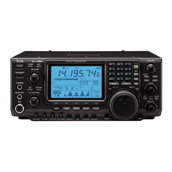
INSTRUCTION MANUAL
VHF/HF ALL MODE TRANSCEIVER
i746
This device complies with Part 15 of the FCC rules. Operation is sub-
ject to the following two conditions: (1) This device may not cause
harmful interference, and (2) this device must accept any interference
received, including interference that may cause undesired operation.
Advertisement
Table of Contents

Subscribe to Our Youtube Channel
Related Manuals for Icom IC-746


Summary of Contents for Icom IC-746
- Page 1 INSTRUCTION MANUAL VHF/HF ALL MODE TRANSCEIVER i746 This device complies with Part 15 of the FCC rules. Operation is sub- ject to the following two conditions: (1) This device may not cause harmful interference, and (2) this device must accept any interference received, including interference that may cause undesired operation.
-
Page 2: Important
Other manufacturer’s microphones have different pin tended periods. assignments and connection to the IC-746 may dam- AVOID placing the transceiver in excessively dusty en- age the transceiver. vironments or in direct sunlight. -
Page 3: Table Of Contents
TABLE OF CONTENTS IMPORTANT ......ii 7-3 Transferring a memory to VFO ... 50 PRECAUTIONS . -
Page 4: Panel Description
PANEL DESCRIPTION 1-1 Front panel Å Å TUNER POWER TRANSMIT PHONES APF/ANF ı ELEC-KEY RF/SQL q POWER SWITCH [POWER] • When the tuner cannot tune the antenna, the tuning Push momentarily to turn power ON. (p. 11) circuit is bypassed automatically after 20 sec. •... - Page 5 PANEL DESCRIPTION !3 RF GAIN/SQUELCH CONTROL [RF/SQL] (p. 12) • Setting RF gain Adjusts the RF gain and squelch threshold level. Maximum RF gain The squelch removes noise output from the speaker Maximum RF gain Adjustable (closed condition) when no signal is received. sensitivity range •...
- Page 6 • [GENE] selects the general coverage band. Push the same key 2 or 3 times to call up stacked frequencies in the band. • Icom’s band stacking register memorizes 3 frequen- cies (and modes) in each band. @7 FREQUENCY INPUT SWITCH [F-INP] (p. 17) Toggles keypad input between frequency and band.
- Page 7 PANEL DESCRIPTION ´ #1 #2 #3 #5 #6 $0 $1 MP-W MP-R LOCK TX CLEAR RIT/ TX SPEECH LOCK #1 TUNING DIAL #9 LOCK SWITCH [LOCK] (p. 40) Changes the displayed frequency, selects set mode Turns the dial lock function ON and OFF. items, etc.
-
Page 8: Rear Panel
PANEL DESCRIPTION Ï Ï TWIN PBT M VFO CALL M-CL M-CH $5 PASSBAND TUNING CONTROLS [TWIN PBT] $8 MEMORY WRITE SWITCH [MW] (p. 51) (p. 41) Stores the selected readout frequency and operat- Adjust the receiver’s “passband width” of the 455 ing mode into the displayed memory channel when kHz and 9 kHz IF filters for the inner and outer con- pushed for 2 sec. -
Page 9: Function Display
PANEL DESCRIPTION 1-3 Function display LSBUSBCW TUNE RTTY RAM WFM CALL CALL BLANK BLANK 100% VFOA VFOA VFOB VFOB MEMO MEMO SPLIT SPLIT COMP MONI TSQL COMP MONI TSQL q ANTENNA TUNER INDICATORS (pgs. 59, 79) !2 MEMORY CHANNEL INDICATOR (p. 49) “TUNE”... -
Page 10: Menu Selection
MENU SELECTION Depending on the mode and menu item selected, the Pushing [MENU] toggles between menu set 1 ( action of the multi-function keys ([F1] to [F5]) changes. and menu set 2 ( ) in the function display. 2-1 Menu set 1 flow chart SSB MODE RTTY MODE BLANK... -
Page 11: Menu Set 2 Flow Chart
MENU SELECTION 2-2 Menu set 2 flow chart BLANK 100% VFOA SET MODE (p. 60) LCD MENU SCAN MENU (p. 66) (pgs. 56–58) VFO MODE MEMORY MODE MEMORY NAME MENU (p. 53) SCAN SET MENU NAME EDIT MENU (p. 55) (p. -
Page 12: Basic Operation
BASIC OPERATION 3-1 Before operating Before applying power for the first time, check the fol- lowing points: Å BEFORE APPLYING POWER Is the connected external power supply capable of delivering more than 20 A? Are the antenna(s) connected properly? • [ANT1/2]: HF/50 MHz antenna •... -
Page 13: Adjusting Volume
BASIC OPERATION ı APPLYING POWER When applying power to the transceiver for the first time, it’s a good idea to reset the CPU (see p. 81 for details) as follows: [F-INP] [M-CL] [POWER] While pushing [F-INP] + [M-CL], push [POWER] to turn power ON. -
Page 14: Squelch And Receive (Rf) Sensitivity
BASIC OPERATION 3-2 Squelch and receive (RF) Adjusts the RF gain and squelch threshold level. The squelch removes noise output from the speaker sensitivity (closed condition) when no signal is received. • The squelch is particularly effective for FM. It is also avail- able for other modes. -
Page 15: Selecting Vfo/Memory Mode
BASIC OPERATION 3-3 Selecting VFO/memory mode Rotating the tuning dial selects frequencies in VFO mode or pre-programmed memories in memory mode. [V/M] Push [V/M] to toggle between memory and VFO modes. • Pushing [V/M] for 2 sec. transfers the contents of the se- lected memory channel to VFO mode (p. -
Page 16: Setting A Band And Frequency
BASIC OPERATION 3-5 Setting a band and frequency The transceiver has a triple band stacking register. This means that the last 3 operating frequencies and modes used on a particular band are automatically Å SETTING AN OPERATING BAND memorized. See the table below for a list of the bands available and the default settings for each register. - Page 17 BASIC OPERATION ı SETTING A FREQUENCY WITH THE Frequencies can be selected with the tuning dial or di- rectly with the keypad (p. 17). When using the tuning TUNING DIAL dial, the frequency changes according to the set tun- ing step. Tuning step defaults differ depending on op- erating mode as shown below.
- Page 18 BASIC OPERATION TOGGLING THE TS FUNCTION ON AND OFF The tuning step function can be turned ON and OFF. When the TS function is ON (default), rotating the tun- ing dial changes the frequency in the set tuning steps. Push [TS] to turn the tuning step function ON, if nec- essary.
-
Page 19: Selecting An Operating Mode
BASIC OPERATION Ç SETTING A FREQUENCY VIA THE KEYPAD The keypad can be used to enter frequencies directly. Push [F-INP] to activate keypad input. Lights when keypad input is activated Enter the desired frequency using the correspond- Keypad [F-INP] ing digit keys on the keypad. •... -
Page 20: Using Different Operating Modes
USING DIFFERENT OPERATING MODES 4-1 Operating SSB Push a band key to select the desired band. Push [SSB] to select LSB or USB. • Below 10 MHz LSB is automatically selected; above 10 Å RECEIVING MHz USB is automatically selected. Rotate [AF] to set audio to a comfortable listening [BAND] level. - Page 21 USING DIFFERENT OPERATING MODES ı TRANSMITTING Before transmitting, monitor your selected operating frequency to make sure transmitting won’t cause inter- [TRANSMIT] Band keys ference to other stations on the same frequency. Connect the microphone to the [MIC] connector. Push a band key to select the desired operating band.
-
Page 22: Operating Cw
USING DIFFERENT OPERATING MODES 4-2 Operating CW Push a band key to select the desired band. Push [CW/RTTY] to select CW or CW-R. • Push [CW/RTTY] for 2 sec. to toggle between CW and Å RECEIVING CW-R modes. Rotate [AF] to set audio to a comfortable listening Band keys level. - Page 23 USING DIFFERENT OPERATING MODES Convenient functions for receive q Preamplifier and attenuator (p. 38) The preamp amplifies received signals in the front end circuit to improve the S/N ration and sensitivity. The at- tenuator prevents a desired signal from distorting when very strong signals are near the desired fre- quency or when very strong electric fields, such as from a broadcasting station, are near you.
- Page 24 USING DIFFERENT OPERATING MODES ı TRANSMITTING Before transmitting, monitor your selected operating frequency to make sure transmitting won’t cause inter- Band keys ference to other stations on the same frequency. [TRANSMIT] Connect an electronic keyer or paddle to the [ELEC- KEY] jack on the rear panel of the transceiver (p.
-
Page 25: Electronic Keyer Functions
USING DIFFERENT OPERATING MODES Ç ELECTRONIC KEYER FUNCTIONS The transceiver has a number of convenient functions for the electronic keyer that can be accessed from the memory keyer menu. (1) Memory keyer settings menu Push [CW/RTTY] to select CW mode. Push [MENU] to select Push [F4] to select the memory keyer menu. - Page 26 USING DIFFERENT OPERATING MODES Pre-set characters can be sent using the memory (2) Memory keyer send menu keyer send menu. Contents of the memory keyer are set using the edit menu. TRANSMITTING Push [TRANSMIT] to set the transceiver to transmit, or set the break-in function ON (p.
- Page 27 USING DIFFERENT OPERATING MODES The contents of the memory keyer memories can be (3) Memory keyer edit menu set using the memory keyer edit menu. The memory keyer can memorize and re-transmit 4 CW key codes for often-used CW sentences, contact numbers, etc. Total capacity of the memory keyer is 50 characters per memory channel.
- Page 28 USING DIFFERENT OPERATING MODES This menu is used to set the contact (serial) number (4) Contact number menu and count up trigger, etc. Push [F1] or [F2] to select the set contents. Rotate the tuning dial to set the condition. •...
- Page 29 USING DIFFERENT OPERATING MODES This menu is used to set the CW side tone, memory (5) CW keyer set menu keyer repeat time, dash weight, paddle specifications, keyer type, etc. Push [F1] or [F2] to select the set contents. Rotate the tuning dial to set the condition. •...
-
Page 30: Operating Rtty (Fsk)
USING DIFFERENT OPERATING MODES 4-3 Operating RTTY (FSK) Before operating RTTY be sure to consult the manual that came with your TNC. Å RECEIVING Connect RTTY capable TNC and personal computer or an RTTY terminal (p. 68) Band keys Push a band key to select the desired band. Push [CW/RTTY] to select RTTY. - Page 31 USING DIFFERENT OPERATING MODES ı TRANSMITTING Before transmitting, monitor your selected operating frequency to make sure transmitting won’t cause inter- Band keys [TRANSMIT] ference to other stations on the same frequency. Connect RTTY capable TNC and personal computer or an RTTY terminal (p. 68) Push a band key to select the desired band.
-
Page 32: Operating Am
USING DIFFERENT OPERATING MODES 4-4 Operating AM Push a band key to select the desired band. Push [AM/FM] to select AM. • Pushing [AM/FM] toggles between AM and FM opera- Å RECEIVING tion. Rotate [AF] to set audio to a comfortable listening Band keys level. - Page 33 USING DIFFERENT OPERATING MODES ı TRANSMITTING Before transmitting, monitor your selected operating frequency to make sure transmitting won’t cause inter- Band keys ference to other stations on the same frequency. [TRANSMIT] Connect a microphone to the [MIC] connector. Push a band key to select the desired band. Push [AM/FM] to select AM.
-
Page 34: Operating Fm
USING DIFFERENT OPERATING MODES 4-5 Operating FM Push a band key to select the desired band. Push [AM/FM] to select FM. • Pushing [AM/FM] toggles between AM and FM opera- Å RECEIVING tion. Rotate [AF] to set audio to a comfortable listening Band keys level. - Page 35 USING DIFFERENT OPERATING MODES Convenient functions for receive q Preamplifier and attenuator (p. 38) The preamp amplifies received signals in the front end circuit to improve the S/N ration and sensitivity. The at- tenuator prevents a desired signal from distorting when very strong signals are near the desired fre- quency or when very strong electric fields, such as from a broadcasting station, are near you.
-
Page 36: Repeater Operation
USING DIFFERENT OPERATING MODES 4-6 Repeater operation A repeater amplifies received signals and retransmits them at a different frequency. When using a repeater, the transmit frequency is shifted from the receive fre- quency by an offset frequency. A repeater can be ac- cessed using split frequency operation with the shift frequency set to the repeater’s offset frequency. - Page 37 USING DIFFERENT OPERATING MODES AUTO REPEATER FUNCTION This function automatically activates the repeater set- tings (DUP or DUP– and tone encoder ON/OFF) when NOTE: This function is available for the USA ver- the operating frequency falls within the general re- sion only.
-
Page 38: Packet Operation
USING DIFFERENT OPERATING MODES 4-7 Packet operation Before operating packet (AFSK) be sure to consult the operating manual that came with your TNC. Å RECEIVING Connect a TNC and personal computer (p. 68) Push a band key to select an operating band. Band keys Push a mode key to select an operating mode. -
Page 39: Functions For Receive
FUNCTIONS FOR RECEIVE 5-1 Simple band scope The band scope function allows you to visually check signal condition around a specified frequency. The IC- 746’s band scope function can be used not only in FM mode but also when operating on HF bands. Sweep indicator Band scope indicator Frequency indicator mark... -
Page 40: Preamp And Attenuator
FUNCTIONS FOR RECEIVE 5-2 Preamp and attenuator The preamp amplifies received signals in the front end circuit to improve the S/N ratio and sensitivity. Set this to preamp 1 or preamp 2 when receiving weak signals. The attenuator prevents a desired signal from distort- ing when very strong signals are near the desired fre- quency or when very strong electric fields, such as from a broadcasting station, are near your location. -
Page 41: Agc Function
FUNCTIONS FOR RECEIVE 5-4 AGC function The AGC (auto gain control) controls receiver gain to produce a constant audio output level even when the received signal strength is varied by fading, etc. While menu set 1 is displayed, push [F1]( ) one or more times to select AGC fast or AGC slow. -
Page 42: Noise Reduction
FUNCTIONS FOR RECEIVE 5-7 Noise reduction The noise reduction function reduces noise compo- nents and picks out desired signals which are buried in noise. The received AF signals are converted to dig- [NR] ital signals and then the desired signals are separated from the noise. -
Page 43: Twin Pbt
FUNCTIONS FOR RECEIVE 5-10 Twin PBT The PBT function electronically narrows the receiver’s IF passband widths to reduce interference. Moving both [TWIN PBT] controls to the same position shifts [TWIN PBT] the IF. Rotate the [TWIN PBT] controls to adjust this func- tion. -
Page 44: Selecting If Filters
5-11 Selecting IF filters Optional filters can be installed in the IF stage of the IC-746 (p. 78). Both 9 MHz and 455 kHz IF filters are available. When an optional filter is installed, set the optional filter setting using filter program mode (see below). -
Page 45: Functions For Transmit
FUNCTIONS FOR TRANSMIT 6-1 VOX function The VOX function starts transmission without pushing the transmit switch or PTT switch when you speak into the microphone; then, automatically returns to receive when you stop speaking. This function is available for SSB, AM and FM modes. Before using this function, follow the steps below. -
Page 46: Break-In Function
FUNCTIONS FOR TRANSMIT 6-2 Break-in function The break-in function is used in CW mode to automat- ically toggle the transceiver between transmit and re- ceive when keying. The IC-746 is capable for full break-in or semi break-in. [KEY SPEED] [VOX/BK-IN] Tuning dial Å... -
Page 47: Tx Function
FUNCTIONS FOR TRANSMIT TX function TX functions shifts the transmit frequency up to ±9.99 kHz in 10 Hz steps without moving the receive frequency. Push [ TX] to toggle the TX function ON and OFF. • “ TX” appears when the function is ON. Rotate the [RIT/ TX] control to set the desired frequency. -
Page 48: Speech Compressor
FUNCTIONS FOR TRANSMIT 6-5 Speech compressor The RF speech compressor increases the average RF output power, improving signal strength and readability in SSB and AM modes. Push [SSB] or [AM/FM] to select SSB or AM mode. While menu set 1 is selected, push [F3]( ) to turn the speech compressor ON. -
Page 49: Split Frequency Operation
FUNCTIONS FOR TRANSMIT 6-6 Split frequency operation Split frequency operation allows you to transmit and re- ceive in the same mode on two different frequencies, one in VFO A, the other in VFO B. Lights during split operation [SPLIT] [XFC] Tuning dial [EXAMPLE]: Operating split with VFO A set to receive 7.06200 MHz/LSB;... -
Page 50: Quick Split Function
FUNCTIONS FOR TRANSMIT 6-7 Quick split function When you push [SPLIT] for 2 sec., split frequency op- eration is turned ON and VFO B is automatically changed according to the plus/minus shift frequency • Setting the frequency while pushing [XFC] programmed in set mode (p. -
Page 51: Memory Channels
MEMORY CHANNELS 7-1 General The transceiver has 101 memory channels (plus 1 call channel). Memory mode is useful for quickly changing often-used frequencies. All 101 memory channels are tuneable, which means the programmed frequency can be tuned temporarily with the tuning dial in memory mode. MEMORY TRANSFER OVER-... -
Page 52: Transferring A Memory To Vfo
MEMORY CHANNELS ı IN MEMORY MODE Push [V/M] to select memory mode. Rotate [M-CH] to select a memory channel. • All memory channels including blank channels can be selected. • Memory channels can also be selected using the micro- phones [UP]/[DN] keys. 100% MEMO 7-3 Transferring a memory to VFO... -
Page 53: Selecting The Call Channel
MEMORY CHANNELS 7-5 Selecting the call channel By default 145.00000 MHz/FM is programmed into the call channel. However, this can be changed to suit your operating preferences (p. 52). [CALL] Push [CALL] to select the call channel. • “C” appears. Push [CALL] again to return to the previous mode. -
Page 54: Programming The Call Channel
MEMORY CHANNELS 7-7 Programming the call channel The call channel is programmed in the same way reg- ular memory channels are. It’s convenient to program a most-often-used frequency into the call channel for [MW] [V/M] [M-CH] quick recall. As with memory channels, the call chan- nel can also hold split frequencies. -
Page 55: Assigning Memory Names
MEMORY CHANNELS 7-9 Assigning memory names Memory names can be assigned to any memory chan- nel. Memory names can be up to 9 characters in length; any of the 127 standard ASCII characters (as [0]–[9], [ • ] [V/M] on a computer keyboard) can be used. [EXAMPLE]: Programming “DX spot”... -
Page 56: Memo Pads
MEMORY CHANNELS 7-10 Memo pads The transceiver has a memo pad function to store fre- quency and operating mode for easy recall. The memo pads are separate from memory channels. The default number of memo pads is 5 but can be increased to 10 in set mode, if desired. -
Page 57: Scan Operation
SCAN OPERATION 8-1 Scan types PROGRAMMED SCAN ∂F SCAN Repeatedly scans between two scan edge frequencies Repeatedly scans within ∂F span area. (scan edge memory channels P1 and P2). Start frequency Scan edge Scan edge P1 or P2 P2 or P1 ∂F frequency +∂F frequency –... -
Page 58: Programmed Scan And Fine Programmed Scan
SCAN OPERATION 8-2 Programmed scan and fine programmed scan [TS] [V/M] Programmed scan searches for signals between scan edge memory channels P1 and P2. The default fre- quencies for these memories are 0.500000 MHz and 29.99999 MHz, respectively. See p. 56 for program- ming scan edges. -
Page 59: Memory Scan
SCAN OPERATION 8-3 Memory scan Memory scan searches through memory channel 1 to 99 for signals. Blank (unprogrammed) memory chan- nels are skipped. Push [V/M] to select memory mode, if necessary. Push [MENU] to select Push [F1] to select the scan menu. Push [F1] to start/stop memory scan. -
Page 60: F Scan And Fine F Scan
SCAN OPERATION F scan and Fine F scan F scan searches on either side of the displayed memory channel or frequency. The frequency range searched on either side of the center frequency (mem- Key pad [V/M] ory channel) is specified by the span. Push [V/M] to select memory mode or VFO mode, as desired. -
Page 61: Internal Antenna Tuner
INTERNAL ANTENNA TUNER 9-1 Before operating The internal automatic antenna tuner matches the transceiver to the connected antenna automatically. Once the tuner matches an antenna, the variable ca- [TUNER] pacitor angles are memorized as a preset point for each frequency range (100 kHz steps). Therefore, when you change the frequency range, the variable ca- pacitors are automatically preset to the memorized point. -
Page 62: Set Mode
SET MODE 10-1 Selecting set mode Set mode is used for programming infrequently changed values or conditions of functions. Push [MENU] to select , if necessary. Push [F5] to enter set mode. Push [F1] or [F2] to change the selected item. •... - Page 63 SET MODE When an optional filter is installed in the 9 MHz filter socket (2), this selection is necessary, otherwise the filter cannot be selected. FL-103, FL223, FL-100, FL-232 or FL-101 can be se- lected. See p. 42 for details. When an optional filter is installed in the 455 kHz filter socket, this selection is necessary, otherwise the fil- ter cannot be selected.
- Page 64 SET MODE When this item is ON, the tuning dial can be used to adjust the transmit frequency while pushing [XFC] even while the lock function is activated. See p. 47 for split frequency operation details. This item sets the offset (difference between transmit and receive frequencies) for the quick split function when operating on an HF band in FM mode only.
- Page 65 SET MODE Tuning of the external antenna tuner can be started automatically at the moment the PTT is pushed after is the operating frequency is changed (more than 1% from the last-tuned frequency). You can set the antenna connector selection to auto- matic, manual or non-selection (when using 1 an- tenna only).
-
Page 66: Set Mode
To distinguish equipment, each CI-V transceiver has its own Icom standard address in hexadecimal code. The IC-746’s is 56h. When 2 or more IC-746’s are connected to an op- tional CT-17 , rotate the tuning dial LEVEL CONVERTER to select a different address for each IC-746 in the range 01h to 7Fh. -
Page 67: Adjustments
ADJUSTMENTS 11-1 Tuning dial brake The tension of the tuning dial can be adjusted to suit your preference. The brake adjustment screw is located on the right side of the tuning dial. See figure at left. Turn the brake adjustment screw clockwise or coun- terclockwise to obtain a comfortable tension level while tuning the dial continuously and evenly in one direction. -
Page 68: Measuring Swr
ADJUSTMENTS 11-3 Measuring SWR The IC-746 has a built-in circuit for measuring antenna SWR while in SSB mode — no external equipment or special adjustments are necessary. Make sure the antenna whose SWR you want to mea- sure is connected, that output power is set to 30 W or more and that [TUNER] is OFF. -
Page 69: Setup And Connections
SETUP AND CONNECTIONS 12-1 Front panel ELECTRONIC KEYER HEADPHONES dash When using the internal electronic keyer connect a paddle. TWIN PBT HF/VHF TRANSCEIVER 1.8 1 3.5 2 TUNER POWER F-INP TRANSMIT SPLIT M VFO CALL GENE 144ENT M-CL M-CH PHONES MP-W MP-R APF/ANF... -
Page 70: Rear Panel
Accepts a paddle to activate the internal electronic keyer. ALC JACK (p. 79) Connects to the ALC output jack of a non- Icom linear amplifier. ALC input: 0–4 V. SEND JACK (p. 79) Goes to ground when transmitting for exter- nal equipment such as a linear amplifier. -
Page 71: Selecting A Location
Make sure: • The [POWER] switch is OFF. • Output voltage of the power source is 12–15 V when you use a non-Icom power supply. • DC power cable polarity is correct. Red: positive + terminal... -
Page 72: Grounding
In this case, an antenna tuner is useful to match the transceiver and antenna. Low SWR allows full power for transmitting even when using the antenna tuner. The IC-746 has a SWR meter to monitor the antenna SWR continuously. PL-259 CONNECTOR INSTALLATION EXAMPLE... - Page 73 [ANT] nector for the 144 MHz band; a total of 3 antenna con- nectors. For each operating band the IC-746 covers, there is a band memory which can memorize a selected an- tenna. When you change the operating frequency be- yond a band, the previously used antenna is automatically selected (see below) for the new band.
-
Page 74: Data Communications
SETUP AND CONNECTIONS 12-7 Data communications The IC-746 can be connected to AMTOR/PACKET or AFSK teletype units via the rear panel ACC sockets or the front panel [MIC] connector. When using such units be sure to consult the appropriate manuals. -
Page 75: Rtty Connections
SETUP AND CONNECTIONS 12-8 RTTY connections When operating RTTY, a teletype and demodulator, etc. must be connected as in the diagrams below. The demodulator operates via audio input with a receive tone of 2125 Hz (or 1275 or 1615) and a shift offset of 170 Hz (or 200 or 425 Hz). -
Page 76: Remote Jack
Interface-V (CI-V) controls the following func- computer tions of the transceiver. ct- 17 Up to 4 Icom CI-V transceivers or receivers can be connected to a personal computer equipped with an RS-232C port. See p. 64 for setting the CI-V condition mini-plug cable using set mode. -
Page 77: Setup And Connections
SETUP AND CONNECTIONS COMMAND TABLE Cn Sc Description Cn Sc Description Sets frequency (transceive) Sets 10 Hz tuning step* Sets mode (transceive) Sets 100 Hz tuning step Reads band edge frequency Sets 1 kHz tuning step Reads display frequency Sets 5 kHz tuning step Reads display mode Sets 9 kHz tuning step Sets frequency... -
Page 78: Optional Installations
OPTIONAL INSTALLATIONS 13-1 Opening the transceiver’s Remove the 2 screws from the left side of the trans- ceiver to remove the carrying handle. case Remove 6 screws from the top of the transceiver and 6 screws from the sides, then lift up the top Follow the case and cover opening procedures shown cover. -
Page 79: Voice Synthesizer Unit
OPTIONAL INSTALLATIONS 13-2 UT-102 The UT-102 announces the accessed readout’s fre- VOICE SYNTHESIZER UNIT quency, mode, etc. (S-meter level can also be an- nounced—p. 63) in a clear, electronically-generated voice, in English (or Japanese). Remove the bottom and shield covers. Remove the protective paper attached to the bottom of the UT-102 to expose the adhesive strip. -
Page 80: Optional If Filters
D INSTALLATION Remove the bottom cover (p. 76). Several IF filters are available for the IC-746. You can Turn the transceiver upside down. Install the desired install 2 filters for the 9 MHz IF and 1 filter for the 455 filter as shown in the diagram below. -
Page 81: Linear Amplifier Connections
(supplied with the IC-PW1) ACC(2) ANT1 EXCITER IC-PW1 ground IC-746 to AC outlet NOTE: Turn OFF the transceiver’s antenna tuner while tuning the IC-PW1’s tuner. CONNECTING A NON-ICOM LINEAR AMPLIFIER Supplied cable Antenna Non-Icom linear amplifier IC-746 RF INPUT RF OUTPUT SEND SEND NOTE: The specifications for the SEND relay are... -
Page 82: External Antenna Tuner Connections
OPTIONAL INSTALLATIONS 13-6 External antenna tuner connections CONNECTING THE AH-4 long wire antenna supplied cable IC-746 ANT 1 AH-4 control cable NOTE: The AH-4 must be connected to [ANT1]. D OPERATING THE AH-4 [TUNER] Connect the AH-4 to the transceiver as shown above. -
Page 83: Maintenance
CAUTION: DISCONNECT the DC power cable from the transceiver when changing a fuse. The IC-746 has 2 types of fuses installed for trans- ceiver protection. • DC power cable fuses ......FGB 20 A • Circuitry fuse ..........FGB 5 A CIRCUITRY FUSE REPLACEMENT The 13.8 V DC from the DC power cable is applied to... -
Page 84: Troubleshooting
The following chart is designed to help you correct If you are not able to locate the cause of a problem or problems which are equipment malfunctions. solve it through the use of this chart, contact your near- est Icom Dealer or Service Center. PROBLEM POSSIBLE CAUSE SOLUTION REF. -
Page 85: Maintenance
MAINTENANCE PROBLEM POSSIBLE CAUSE SOLUTION REF. Transmitting is impossi- The operating frequency is not set to Set the frequency to a ham band. p. 84 ble. a ham band. The split frequency function is turned Turn OFF the split frequency function. p. -
Page 86: Specifications And Options
SPECIFICATIONS AND OPTIONS 15-1 Specifications RECEIVER • Sensitivity (typical) USB, LSB, AM, RTTY 0.16 µV* GENERAL (1.8–29.990 MHz) 0.13 µV* (10 dB S/N) (50 MHz) • Frequency coverage : Unit: MHz 0.11 µV* Receive 0.030– 60.000* (144 MHz) 13 µV 108.000–... -
Page 87: Options
CT-16 SATELLITE INTERFACE UNIT Designed for base station operation. UT-102 VOICE SYNTHESIZER UNIT Easy tuning when connecting another Input impedance: 8 Announces operating frequency, mode Icom VHF/UHF transceiver for instant Max. input power: 5 W and S-meter level. satellite communications. - Page 88 Count on us! A-5482H-1EX-i Printed in Japan 6-9-16 Kamihigashi, Hirano-ku, Osaka 547-0002 Japan © 1997 Icom Inc.
- Page 89 127 standard ASCII characters (as on a computer keyboard) can be used. On page 53 of the IC-746 Instruction Manual, the text at right appears regarding assigning memory names. The following [EXAMPLE]: Programming “DX spot” into memory should be added to the bullet list in step ➅:...
- Page 90 ERRATUM Please note that the instruction manual for the IC-746 does not list the supplied accessories as shown below. Accessories supplied with the IC-746: Qty. ➀ DC power cable (OPC-025A) ....1 ➁...
Need help?
Do you have a question about the IC-746 and is the answer not in the manual?
Questions and answers