Icom IC-746PRO Manual
Hide thumbs
Also See for IC-746PRO:
- Instruction manual (116 pages) ,
- Service manual (7 pages) ,
- Technical information (7 pages)
Table of Contents
Advertisement
Quick Links
• Thank you for checking the interactive view of the
IC-746PRO.
– Use your mouse to navigate through the presentation by
clicking the desired control or function.
– To start this tour click either the
view.
– Use the arrow button at the bottom of each page to return
to the previous slide.
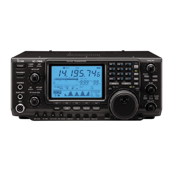
IC-746PRO
Front Panel
or
Rear Panel
Advertisement
Table of Contents

Subscribe to Our Youtube Channel
Related Manuals for Icom IC-746PRO


Summary of Contents for Icom IC-746PRO
- Page 1 IC-746PRO • Thank you for checking the interactive view of the IC-746PRO. – Use your mouse to navigate through the presentation by clicking the desired control or function. – To start this tour click either the Front Panel Rear Panel view.
-
Page 2: Front Panel
Front Panel Rear Panel... -
Page 3: Rear Panel
Rear Panel Front Panel... -
Page 4: Power Connector
POWER Connector • Accepts 13.8 V DC through the supplied DC power cable (OPC-025D). - Page 5 TX Indicator • Lights red while transmitting.
- Page 6 RX Indicator • Lights green while receiving a signal and when the squelch is open.
-
Page 7: Lock Indicator
Lock Indicator • Lights when the dial lock function is activated. • The dial lock function prevents accidental changes caused by the tuning dial. – Push [LOCK/SPCH] to turn the dial lock function ON and OFF. – “LOCK” indicator lights while the dial lock function is activated. –... - Page 8 Split Indicator • Lights during split operation. • Split frequency operation allows you to transmit and receive in the same mode on two different frequencies. • The split frequency operation is basically performed using 2 frequencies in VFO A and VFO B. •...
- Page 9 Frequency Input Indicator • Lights during frequency input from the keypad is enable. • The transceiver has a keypad for direct frequency. – Push [F-INP]. • F-INP indicator lights – Input the desired frequency. – Input “•” (decimal point) between the MHz units and kHz units. –...
-
Page 10: Power Switch
POWER Switch • Push momentarily to turn power ON. – Turn the optional DC power supply ON in advance. • Push for 1 sec. to turn power OFF. - Page 11 AH-4 Connector • Connection for the AH-4 Automatic Antenna Tuner.
-
Page 12: Acc Connectors
ACC Connectors • Connectors used for Accessories... -
Page 13: Ground Connectors
Ground Connectors • To prevent electrical shock, television interference (TVI), broadcast interference (BCI) and other problems, ground the transceiver through the GROUND terminal on the rear panel. • For best results, connect a heavy gauge wire or strap to a long earth- sunk copper rod. -
Page 14: Remote Connector
LEVEL CONVERTER to a personal computer equipped with an RS- 232C port. The Icom Communications Interface-V (CI-V) controls the following functions of the transceiver. • Up to 4 Icom CI-V transceivers or transceivers can be connected to a personal computer equipped with an RS-232C port. -
Page 15: External Speaker
External Speaker • Jack for an External speaker. – 2-conductor • 3.5 (d) mm • 8W • More than 2.0 W at 10% distortion with an 8Ω load... - Page 16 SEND Connector • Goes to ground while transmitting to control external equipment such as a linear amplifier. – Max. control level: 16 V DC/0.5 A...
- Page 17 ALC Connector • Connects to the ALC output jack of a non- Icom linear amplifier. – WARNING: Set the transceiver output power and linear amplifier ALC output level referring to the linear amplifier instruction manual. • The ALC input level must be in the range 0 V to –4 V, and the transceiver does not...
- Page 18 Key Jack Rear • Jack to be used for Keying via a Straight Key or Computer.
-
Page 19: Data Connector
Data Connector • Data connection for Packet operation. -
Page 20: Transmit Frequency Check
TRANSMIT FREQUENCY CHECK • Monitors the transmit frequency when pushed and held. – While pushing this switch, the transmit frequency can be changed with the tuning dial, keypad or memo pad. – When the split lock function is turned ON, pushing [XFC] cancels the dial lock function. - Page 21 – [GENE] selects the general coverage band. – Pushing the same key 2 or 3 times calls up other stacked frequencies in the band. • ICOM's triple band stacking register memorizes 3 frequencies in each band. – After pushing [F-INP], enters a keyed frequency.
- Page 22 Triple BSR Example • Push [14 5], then select a frequency and an operating mode. – Frequency and operating mode are memorized in the first band stacking register. • Push [14 5] again, then select another frequency and operating mode. –...
- Page 23 Triple Band Stacking Register • The transceiver has a triple band stacking register. – This means that the last 3 operating frequencies and modes used on a particular band are automatically memorized.
- Page 24 Memory Pad Write • Programs the selected readout frequency and operating mode into a memo pad. – The 5 most recent entries remain in memo pads. – The transmit frequency is programmed when pushed together with [XFC]. • The memo pad capacity can be expanded from 5 to 10 in set mode for your convenience.
- Page 25 Memory Pad Read • Each push calls up a frequency and operating mode in a memo pad. The 5 (or 10) most recently programmed frequencies and operating modes can be recalled, starting from the most recent. – The memo pad capacity can be expanded from 5 to 10 in set mode for your convenience.
- Page 26 • Push to toggle between VFO A and VFO B. – Push for 1 sec. to equalize the frequency and operating mode of the two VFO’s.
- Page 27 Split • Turns the split function ON and OFF when pushed. • Turns the quick split function ON, when pushed for 1 sec. – The offset frequency is shifted from the displayed frequency. – The quick split function can be turned OFF using set mode.
-
Page 28: Frequency Input
Frequency Input • Push to toggle keypad input between frequency and band. – The frequency input indicator lights during frequency input is selected for the keypad. - Page 29 M-CH Knob • Selects a memory channel. – Rotate clockwise to increase the memory channel; rotate counterclockwise to decrease the memory channel.
- Page 30 • Switches the selected readout operating mode between the VFO mode memory mode when pushed. – Transfers the memory contents to VFO when pushed for 1 sec.
-
Page 31: Memory Write
Memory Write • Stores the selected readout frequency and operating mode into the displayed memory channel when pushed for 1 sec. – This function is available both in VFO and memory modes. -
Page 32: Memory Channels
Memory Channels • The transceiver has 101 memory channels (plus 1 call channel). The memory mode is very useful for quickly changing to often-used frequencies. – All 101 memory channels are tunable which means the programmed frequency can be tuned temporarily with the tuning dial, etc. in memory mode. - Page 33 M-CL • Clears the selected readout memory channel contents when pushed for 1 sec. in memory mode. – The channel becomes a blank channel. • Any unnecessary memory channels can be cleared. – This switch does not function in VFO mode.
- Page 34 PBTC • Clears the Twin PBT settings when pushed for 1 sec.
- Page 35 Twin PBT • General PBT (Passband Tuning) function electronically narrows the IF passband width by shifting the IF frequency to slightly outside of the IF filter passband to reject interference. This transceiver uses the DSP circuit for the PBT function. Moving both [TWIN PBT] controls to the same position shifts the IF.
- Page 36 Advanced Twin PBT • Passband width and shift frequency are displayed in the multi-function switch indicator. • [TWIN PBT] should normally be set to the center positions or when the (PBT setting is cleared) best when there is no interference. –...
- Page 37 Advanced Twin PBT Graphs...
- Page 38 • Shows the operating frequency, function switch menus, band scope screen, memory name screen, set mode settings, etc. Click on display for more details...
- Page 39 LCD Breakdown...
-
Page 40: Frequency Readout
Frequency Readout • Show the operating frequency. – Showing MHz, KHz, and depending on the Quick Tuning Step Setting, 1 Hz resolution. - Page 41 RIT Readout • Shows the RIT or ∆TX frequency offset.
- Page 42 VFO Readout • Indicates whether VFO A or VFO B is selected.
- Page 43 Dual VFO • The transceiver has 2 VFOs and are called VFO A and VFO B. You can use the desired VFO to call up a frequency and operating mode for your operation. • Selecting the VFO A/B – Push [A/B] to switch between the VFO A and VFO B. •...
- Page 44 Memory Channel Readout • Appears when the selected memory channel is set as a select memory channel. – Also indicates when the memory channel is blank.
- Page 45 RIT Readout • Shows the RIT or ∆TX frequency offset.
- Page 46 Antenna Readout • Display outlines the antenna being used, Mode, and Voice Scanning Conditions.
- Page 47 Tune Indicators • “TUNE” appears when the antenna tuner is ON; • “TUNE” appears and flashes during manual tuning. – “EXT” appears when the optional AH-4 external antenna tuner is connected to [ANT1].
- Page 48 AH-4 Antenna Tuner Outline • The AH-4 matches the IC-746PRO to a long wire antenna more than 7 m/23 ft long (3.5 MHz and above). – NEVER operate the AH-4 without an antenna wire. The tuner and transceiver will be damaged.
- Page 49 AH-4 Antenna Tuner Outline • The AH-4 matches the IC-746PRO to a long wire antenna more than 7 m/23 ft long (3.5 MHz and above). – NEVER operate the AH-4 without an antenna wire. The tuner and transceiver will be damaged.
- Page 50 AH-4 Antenna Tuner Installation...
- Page 51 – Antenna Selections: • For each operating band the IC-746PRO covers, there is a band memory which can memorize a selected antenna. When you change the operating frequency beyond a band, the previously used antenna is automatically selected (see below) for the new band. This function is convenient when you use 2 antennas...
-
Page 52: Mode Of Operation
Mode of Operation • Shows the selected operating mode. • To select a mode of operation, push the desired mode switch momentarily. Push the switch again to toggle between USB and LSB, CW/CW-R and RTTY/RTTYR, AM and FM, if necessary. –... -
Page 53: Multifunction Display
Multi Function Display • Indicates the functions assigned to the multi-function switches ([F1]–[F5]). – Toggles between menu 1 (M1) and menu 2 (M2). - Page 54 Multi Function Meter Indicator • .Shows receiving signal strength, etc. during receive. – Shows transmit output power, ALC and SWR during transmit.
-
Page 55: Common Functions
Common Functions • Shows the status of commonly used functions. - Page 56 Call • Toggles between the call channel and normal operation when pushed momentarily. • It’s convenient to program a most-often-used frequency into the call channel for quick recall. As with memory channels, the call channel can also hold split frequencies. –...
-
Page 57: Tuning Knob
Tuning Knob • The transceiver has several tuning methods for convenient frequency tuning. • When rotating the tuning dial rapidly, the tuning step automatically changes several times as selected. • The operating frequency can be changed in kHz steps (0.1, 1, 5, 9, 10, 12.5, 20 or 25 kHz selectable) for quick tuning. - Page 58 Auto Tuning Steps • This item sets the auto tuning step function. When rotating the tuning dial rapidly, the tuning step automatically changes several times as selected. – There are 2 type of auto tuning steps: HIGH (Fastest) and LOW (Faster). •...
-
Page 59: Tuning Steps
Tuning Steps • Turns the quick tuning step ON and OFF. – While the quick tuning indicator is displayed, the frequency can be changed in programmed kHz steps. •0.1, 1, 5, 9, 10, 12.5, 20 and 25 kHz quick tuning steps are available. - Page 60 Lock • Push momentarily to toggle the dial lock function ON and OFF. • Pushing for 1 sec. announces the selected readout frequency and S- meter indication when an optional UT-102 is installed.
- Page 61 UT-102 • The UT-102 announces the accessed readout’s frequency, mode, etc. (S- meter level can also be announced in a clear, electronically-generated voice, in English (or Japanese). – Push [LOCK/SPCH] for 1 sec. to announce the frequency, etc.
- Page 62 Knob Tension • The tension of the tuning dial may be adjusted to suit your preference. – The brake adjustment screw is located on the right side of the tuning dial. – Turn the brake adjustment screw clockwise or counterclockwise to obtain a comfortable tension level while turning the dial continuously and evenly in one direction.
- Page 63 RIT Knob • Shifts the receive frequency without changing the transmit frequency while the RIT function is ON. – Rotate the control clockwise to increase the frequency, or rotate the control counterclockwise to decrease the frequency. – The shift frequency range is ±9.99 kHz in 10 Hz steps (or ±9.999 kHz in 1 Hz steps).
- Page 64 ∆TX Knob • Shifts the transmit frequency without changing the receive frequency while the ∆TX function is ON. – Rotate the control clockwise to increase the frequency, or rotate the control counterclockwise to decrease the frequency. – The shift frequency range is ±9.99 kHz in 10 Hz steps (or ±9.999 kHz in 1 Hz steps).
- Page 65 • The RIT (Receiver Incremental Tuning) shifts the receive frequency without shifting the transmit frequency. • This is useful for fine tuning stations calling you on an off-frequency or when you prefer to listen to slightly different sounding voice characteristics, etc.
- Page 66 ∆TX • The ∆TX shifts the transmit frequency without shifting the receive frequency. This is useful for simple split frequency operation in CW, etc.
- Page 67 CLEAR • User selectable on how to clear the RIT/∆TX shift frequency. – Quick RIT Clear this item selects the RIT/∆TX frequency clearing. • ON : Clears the RIT/∆TX frequency when [CLEAR] is pushed momentarily. • OFF : Clears the RIT/∆TX frequency when [CLEAR] is pushed for 1 sec.
- Page 68 PREAMP/ATTENUATOR • Push momentarily to toggle between preamp-1 and preamp-2. – “P.AMP1” activates 10 dB preamp for HF all bands. – “P.AMP2” activates 16 dB high-gain preamp for 24 MHz band and above. • Push for 1 sec. to toggle the attenuator function ON and OFF. –...
-
Page 69: Noise Blanker
Noise Blanker • Switches the noise blanker ON and OFF when pushed. The noise blanker reduces pulse-type noise such as that generated by automobile ignition systems. This function cannot be used for FM, or non-pulse-type noise. – “NB” appears while the noise blanker is activated. –... - Page 70 Noise Blanker • Switches the noise blanker ON and OFF when pushed. The noise blanker reduces pulse-type noise such as that generated by automobile ignition systems. This function cannot be used for FM, or non-pulse-type noise. – “NB” appears while the noise blanker is activated. –...
- Page 71 • Used for VOX and Break-In operations • In SSB, AM and FM modes, push momentarily to turn the VOX function ON and OFF. – Push for 1 sec. to enter VOX set mode. • What is the VOX function? –...
- Page 72 BREAK-IN • In CW mode, push momentarily to turn the semi break-in, full break-in or break-in OFF. – Push for 1 sec. to enter Break-in set mode mode. – What is the break-in function? • The break-in function switches transmit and receive with CW keying. Full break- in (QSK) can monitor the receive signal during keying.
- Page 73 BREAK-IN • In CW mode, push momentarily to turn the semi break-in, full break-in or break-in OFF. – Push for 1 sec. to enter Break-in set mode mode. – What is the break-in function? • The break-in function switches transmit and receive with CW keying. Full break- in (QSK) can monitor the receive signal during keying.
- Page 74 • Used for VOX and Break-In operations • In SSB, AM and FM modes, push momentarily to turn the VOX function ON and OFF. – Push for 1 sec. to enter VOX set mode. • What is the VOX function? –...
- Page 75 VOX/BREAK-IN Set Mode • VOX Set Mode – VOX Gain Sets the sensitivity of the VOX to keep the rig keyed. – Anti VOX Sets the VOX so sounds in the shack do not trigger the VOX. – VOX Delay Sets the interval before returning to receive.
- Page 76 MONITOR • The monitor function allows you to monitor your transmit IF signals in any mode through the speaker. Use this to check voice characteristics while adjusting SSB transmit tones. – The CW sidetone functions when [MONITOR] is OFF in CW mode.
- Page 77 MONITOR • The monitor function allows you to monitor your transmit IF signals in any mode through the speaker. Use this to check voice characteristics while adjusting SSB transmit tones. – The CW sidetone functions when [MONITOR] is OFF in CW mode.
- Page 78 MONITOR Set Mode – Enters to monitor set mode when pushed for 1 sec.
- Page 79 TRANSMIT SWITCH • Selects transmitting or receiving. – The [TX] indicator lights red while transmitting and the [RX] indicator lights green when the squelch is open.
-
Page 80: Headphone Jack
HEADPHONE JACK • Accepts headphones – 1/4‘ mono type jack. • Output power: 5 mW with an 8 Ω load. • When headphones are connected, the internal speaker or connected external speaker does not function. - Page 81 ELECTRONIC KEYER JACK • Accepts a paddle to activate the internal electronic keyer for CW operation. – Selection between the internal electronic keyer, bug-key and straight key operation can be made in keyer set mode. – A straight key jack is separately available on the rear panel. –...
-
Page 82: Microphone Connector
MICROPHONE CONNECTOR • Accepts the supplied or optional microphone. - Page 83 AF/RF/SQUELCH CONTROL • Concentric control for the AF Control RF/Squelch.
- Page 84 AF CONTROL • Inner control varies the audio output level from the speaker or Headphone outputs.
- Page 85 RF/SQUELCH CONTROL • Adjusts the RF gain and squelch threshold level. – The squelch removes noise output from the speaker (closed condition) when no signal is received. • The squelch is particularly effective for FM. It is also available for other modes.
-
Page 86: Mic Gain Control
MIC GAIN CONTROL • Adjusts microphone input gain. – The transmit audio tone in SSB, AM and FM modes can be adjusted in tone control set mode. – How to set the microphone gain. • Set the [MIC] control so that the ALC meter sometimes swings during normal voice transmission in SSB mode. -
Page 87: Rf Power Control
RF POWER CONTROL • Continuously varies the RF output power from minimum – (less than 5 W*) to maximum (100 W*). – * AM mode: less than 5 W to 40 W... -
Page 88: Cw Pitch Control
CW PITCH CONTROL • Shifts the received CW audio pitch and monitored CW audio pitch without changing the operating frequency. – The pitch can be changed from 300 to 900 Hz in approx. 25 Hz steps. - Page 89 ELECTRONIC CW KEYER SPEED • Adjusts the internal electronic CW keyer’s speed. – 6 wpm (min.) to 60 wpm (max.) can be set.
- Page 90 AUTO/MANUAL NOTCH • Toggles the notch function between Manual Notch Automatic Notch when pushed. – What is the notch function? • The notch function eliminates unwanted CW or AM carrier tones while preserving the desired signal’s audio response. • The filtering frequency is adjusted to effectively eliminate unwanted tones via the DSP circuit.
- Page 91 AUTO/MANUAL NOTCH • Toggles the notch function between Manual Notch Automatic Notch when pushed. – What is the notch function? • The notch function eliminates unwanted CW or AM carrier tones while preserving the desired signal’s audio response. • The filtering frequency is adjusted to effectively eliminate unwanted tones via the DSP circuit.
- Page 92 AUTO NOTCH – The auto notch function automatically attenuates more than 3 beat tones, tuning signals, etc., even if they are moving. • “ANOTCH” appears when auto notch is in use. • “NOTCH” appears when manual notch is in use.
- Page 93 NR/NOTCH CONTROL • Concentric control for the Noise Reduction Manual Notch features.
- Page 94 NOTCH – What is the notch function? • The notch function eliminates unwanted CW or AM carrier tones while preserving the desired signal’s audio response. • The filtering frequency is adjusted to effectively eliminate unwanted tones via the DSP circuit.
- Page 95 NOTCH CONTROL • Adjusts the notch filter frequency to remove a interference signal by varying the peak frequency of the manual notch filter to pick out a receive signal from interference while the manual notch function is – Notch filter center frequency: •...
- Page 96 NOISE REDUCTION • Switches the noise reduction ON and OFF. – “NR” appears while the noise reduction is activated. – Used in conjunction with the Noise Reduction control.
- Page 97 NOISE REDUCTION • Switches the noise reduction ON and OFF. – “NR” appears while the noise reduction is activated. – Used in conjunction with the Noise Reduction control.
- Page 98 NOISE REDUCTION LEVEL • Adjusts the noise reduction level when the noise reduction is in use. – The noise reduction function reduces noise components and picks out desired signals which are buried in noise. The received signals are converted to digital signals and then the desired signals are separated from the noise.
- Page 99 [ANT1] and [ANT2], and 1 antenna connector for the 144 MHz band; a total of 3 antenna connectors. – For each operating band the IC-746PRO covers, there is a band memory which can memorize a selected antenna. When you change the operating frequency beyond a band, the previously used antenna is automatically selected.
-
Page 100: Antenna Tuner
ANTENNA TUNER • Momentary pushing the switch turns the antenna tuner ON and OFF. • Pushing for 1 second manually starts the antenna tuner. – The internal automatic antenna tuner matches the transceiver to the connected antenna automatically. Once the tuner matches an antenna, the variable capacitor angles are memorized as a preset point for each frequency range (100 kHz steps). - Page 101 M1 Multi Function Buttons • Push to select the function indicated in the LCD display above these switches. – Functions vary depending on the operating condition. • Push to input a character for memory keyer programming or memory name. • M2 Multi Function Buttons...
- Page 102 M1 Multi Function Buttons • Push to select the function indicated in the LCD display above these switches. – Functions vary depending on the operating condition. • Push to input a character for memory keyer programming or memory name. • M2 Multi Function Buttons...
- Page 103 M2 Multi Function Buttons • Secondary functions for the control of Scanning, Memory Channels, SWR Scope, and Tone Control. – SCN Selects the scan menu. – MEM Selects the memory name screen. – SWR Selects the SWR graph screen. – TCN Selects the audio tone set mode. –...
- Page 104 M2 Multi Function Buttons • Secondary functions for the control of Scanning, Memory Channels, SWR Scope, and Tone Control. – SCN Selects the scan menu. – MEM Selects the memory name screen. – SWR Selects the SWR graph screen. – TCN Selects the audio tone set mode. –...
- Page 105 SCAN • The selection of the type of scanning and the settings for control of the scanning function of the IC-746PRO is found under the SCN Menu. – Scan speed and the scan resume condition can be set using the scan...
-
Page 106: Memory Name
Memory Name • All memory channels (including scan edges) can be tagged with alphanumeric names of up to 9 characters each. Like “DX spot” into memory channel 10. – Push [F1] several times to select the type of characters for input. •... - Page 107 The IC-746PRO has a built-in circuit for measuring antenna SWR— no external equipment or special adjustments are necessary. – The IC-746PRO can measure SWR in 2 ways— spot measurement and plot measurement are available. • Spot Measurement gives the operator the SWR for the given operating frequency.
-
Page 108: Tone Control
Tone Control • Tone levels (bass and treble) for each transmit and receive audio can be set for each phone mode independently. • TX Bass This item adjusts the bass level of the transmit audio tone from –5 dB to +5 dB in 1 dB steps. •... -
Page 109: Program Scanning
PROGRAM Scanning • When in VFO mode, programmed scan searches for signals between scan edge memory channels P1 and P2. The default frequencies for these memories are 0.500000 MHz and 29.99999 MHz, respectively. – If the same frequencies are programmed into the scan edge memory channel P1 and P2, programmed scan does not start. -
Page 110: Fine Programmed Scan
Fine Programmed Scan • Similar to a programmed scan, except when a signal is received. Temporarily the scan continues as the tuning step set to 10 Hz. - Page 111 ∆F scan The ∆F scan searches for signals • within the specified range with the displayed VFO or memory channel frequency as for center frequency. The frequency range is specified by the span. – Set the ∆F span • ±5 kHz, ±10 kHz, ±20 kHz, ±50 kHz, ±100 kHz, ±500 kHz and ±1 MHz are selectable.
- Page 112 Fine ∆F Scan • During ∆F scan, when a signal is received, scan continues, but the tuning step is temporarily set to 10 Hz.
-
Page 113: Memory Scanning
MEMORY Scanning • Memory scan searches through memory channel 1 to 99 for signals. – Blank (un-programmed) memory channels are skipped. • Select Memory Scan searches through memory channel set as “select” for signals. See below for setting and deleting select memory channels. - Page 114 Fine Scanning • There are two types of Fine Scanning. – Fine Program Scan – Fine DF Scan...
- Page 115 Select Memory Scanning • Select memory scan searches through memory channel set as “select” for signals.
- Page 116 SPAN • Sets the ∆F span by pushing. – ±5 kHz, ±10 kHz, ±20 kHz, ±50 kHz, ±100 kHz, ±500 kHz and ±1 MHz are selectable.
- Page 117 Scan Set Mode • When the squelch is open, scan continues until it is stopped manually— it does not pause on detected signals. • When squelch is closed, scan stops when detecting a signal, then resumes according to the scan resume condition. –...
- Page 118 Scan Speed • Rotate the tuning dial to select scan speed from high and low. – “HIGH” : scan is faster – “LOW” : scan is slower...
-
Page 119: Scan Resume
Scan Resume • “ON” : when detecting a signal, scan pauses for 10 sec., then resumes. When a signal disappears, scan resumes 2 sec. later. • “OFF” : when detecting a signal, cancels scanning. - Page 120 • This function is useful when you don’t want unmodulated signals pausing or canceling a scan. When the voice scan control function is activated, the receiver checks received signals for voice components. • If a receiver signal includes voice components, and the tone of the voice components changes within 1 sec., scan pauses (or stops).
- Page 121 SSB Multi Function Buttons • ICOM Smart Menu system adjusts to the mode you are operating. For SSB Operation these are the following functions – AGC Automatic Gain Control – DUP Duplex Operation – CMP RF Speech Compression – TBW Transmit Band Width...
- Page 122 • TBW (Transmit Band Width) – The transmit filter width for SSB mode can be selected from wide, middle and narrow. – Push for 1 sec. to select the transmission passband width. – One of “TX BW=WIDE,” “TX BW=MID” or “TX BW=NAR”...
- Page 123 • AGC (Automatic Gain Control) – What is the AGC? • The AGC controls receiver gain to produce a constant audio output level, even when the received signal strength is varied by fading, etc. Select “FAST” for tuning and select “MID” or “SLOW” depending on the receiving condition.
- Page 124 • AGC (Automatic Gain Control) – What is the AGC? • The AGC controls receiver gain to produce a constant audio output level, even when the received signal strength is varied by fading, etc. Select “FAST” for tuning and select “MID” or “SLOW” depending on the receiving condition.
- Page 125 RTTY Menu • The transceiver has a number of convenient functions for the RTTY operation that can be accessed from the RTTY menu. – RTTY Filter This item sets the RTTY filter width. 250, 300, 350, 500 Hz and 1 kHz can be selected. •...
- Page 126 RTTY Map • The transceiver has a number of convenient functions for the RTTY operation that can be accessed from the RTTY menu.
- Page 127 RTTY Filter • The transceiver has 5 RTTY filters in addition to normal IF filters. The passband width can be selected from 1 kHz, 500 Hz, 350 Hz, 300 Hz and 250 – When the RTTY filter is turned ON, the RTTY tuning meter can be used.
-
Page 128: Rtty Decoder
RTTY Decoder • The transceiver has an RTTY decoder for Baudot – (mark freq.: 2125 Hz, shift freq.: 170 Hz, 45 bps). • An external terminal unit (TU) or terminal node controller (TNC) is not necessary for receiving a Baudot signal. -
Page 129: Rtty Set Mode
RTTY Set mode • This set mode is used to set the mark and shift frequencies, keying type, decode USOS function, etc. – RTTY Mark Sets the mark frequency for RTTY operation. • 1275, 1615 and 2125 Hz are selectable. –... - Page 130 Speech Compression • Push momentarily to turn the RF speech compression function ON/OFF. – “COMP” indicator appears when the speech compressor is ON. • Push for 1 sec. to enter to the compression set mode. – What is the speech compressor? •...
- Page 131 Speech Compression • Push momentarily to turn the RF speech compression function ON/OFF. – “COMP” indicator appears when the speech compressor is ON. • Push for 1 sec. to enter to the compression set mode. – What is the speech compressor? •...
- Page 132 Speech Compression Set Mode • To set up the RF Speech compression, speak normally into the microphone. Rotating the tuning dial so the COMP meter reads within the COMP zone. – When meter peaks above the COMP zone, your transmitted audio may be distorted.
- Page 133 Duplex • Push momentarily to selects the duplex direction or turn the function OFF. – “DUP–” or “DUP+” indicator appears during duplex operation. • Push for 1 sec. to turn the one-touch repeater function ON/OFF.
-
Page 134: One Touch Repeater
One Touch Repeater • This function allow you to set repeater operation with push of one switch. – To set the transceiver for repeater operation using the one-touch repeater function, follow the steps push for 1 sec. • NOTE: Set the offset shift direction and frequency in advance as well as the tone frequency. - Page 135 AGC Set Mode • The AGC (auto gain control) controls receiver gain to produce a constant audio output level even when the received signal strength is varied by fading, etc. – The transceiver has 3 AGC characteristics (time constant; fast, mid, slow) for non-FM mode.
-
Page 136: Band Scope
Band Scope • Allows operators to visually check signal condition around a specified frequency in any operating mode and frequency band. • Reading the Band Scope – Sweep indicator Gives visual indication of scope status. Received audio is not emitted from the speaker while the band scope is “sweeping.”... - Page 137 Band Scope View...
- Page 138 SSB Data Multi Function Buttons • ICOM Smart Menu system adjusts to the mode you are operating. For SSB Operation these are the following functions – AGC Automatic Gain Control – DUP Duplex Operation – ¼ Turn tuning control – SCP RX Band Scope...
- Page 139 ¼ Turn Tuning Control • While operating in SSB data/CW/RTTY, the ¼ function is available for critical tuning. Dial rotation is reduced to ¼ of normal when the ¼ function is in use.
- Page 140 CW Multi Function Buttons • ICOM Smart Menu system adjusts to the mode you are operating. For SSB Operation these are the following functions – AGC Automatic Gain Control – DUP Duplex Operation – ¼ Turn tuning control – KEY Key functions...
- Page 141 Memory Keyer Function • The transceiver has a number of convenient functions for the electronic keyer that can be accessed from the memory keyer menu. – Push to select the memory keyer or keyer send menu.
- Page 142 Memory Keyer Function Map...
- Page 143 Keyer Send Menu • ICOM Pre-set characters can be sent using the keyer send menu. Contents of the memory keyer are set using the edit menu. • Push one of the function keys ([F1] to [F4]) to send the contents of the memory keyer.
- Page 144 Memory Keyer Edit Menu • The contents of the memory keyer memories can be set using the memory keyer edit menu. The memory keyer can memorize and re- transmit 4 CW key codes for often- used CW sentences, contact numbers, etc.
-
Page 145: Contest Number Set Mode
Contest Number Set Mode • This menu is used to set the contest (serial) number and count up trigger, etc. Number Style This item sets the numbering system used for contact (serial) numbers— normal or Morse cut numbers. – NORMAL: Does not use morse cut number (default) –... - Page 146 Keyer Setup Menu • Set mode is used to set the CW side tone, memory keyer repeat time, dash weight, paddle specifications, keyer type, etc. Side Tone Level This item sets the CW side tone output level. – 0 to 100% in 1% step can be selected. Side Tone L-imt This item sets the CW side tone level limit.
- Page 147 Keyer Setup Menu Rise Time This item set the envelop time period which the output power becomes the set transmit power. – 2, 4, 6 or 8 m sec. can be selected. Paddle Polarity This item sets the paddle polarity. –...
- Page 148 RTTY Multi Function Buttons • ICOM Smart Menu system adjusts to the mode you are operating. For SSB Operation these are the following functions – AGC Automatic Gain Control – DUP Duplex Operation – ¼ Turn tuning control – RTY Transmit Band Width...
- Page 149 AM Multi Function Buttons • ICOM Smart Menu system adjusts to the mode you are operating. For SSB Operation these are the following functions – AGC Automatic Gain Control – DUP Duplex Operation – CMP RF Speech Compression – SCP RX Band Scope...
- Page 150 FM Multi Function Buttons • ICOM Smart Menu system adjusts to the mode you are operating. For SSB Operation these are the following functions – AGC Automatic Gain Control – DUP Duplex Operation – CMP RF Speech Compression – TON Tones CTCSS or DTCS...
- Page 151 Tone • Two of the possible signaling formats available on the IC-746PRO CTCSS and DTCS. • Tone squelch or CTCSS operation is a method of communications using selective calling. Only received signal having a matching tone will open the squelch.
- Page 152 CTCSS • Tone squelch or CTCSS operation is a method of communications using selective calling. Only received signal having a matching tone will open the squelch. • Also has decode scan capability.
- Page 153 CTCSS • Tone squelch or CTCSS operation is a method of communications using selective calling. Only received signal having a matching tone will open the squelch. • Also has decode scan capability.
- Page 154 Decode Scan • By monitoring a signal that is being operated with a repeater, tone squelch or DTCS, you can determine the tone frequency necessary to open a repeater or the squelch. • When matched tone or code is found, the scan pauses and the tone frequency or code is set for the selected tone as in step –...
- Page 155 DTCS • DTCS function is an another method of communications using selective calling. Only received signal having a matching 3-digit code will open the squelch. • Also has decode scan capability...
- Page 156 DTCS • DTCS function is an another method of communications using selective calling. Only received signal having a matching 3-digit code will open the squelch. • Also has decode scan capability...
- Page 157 Menu • Push to change the set of functions assigned to the multi-function switches. – Toggles between menu 1 (M1) and menu 2 (M2).
- Page 158 • Selects USB and LSB mode alternately. – Selects SSB data mode (USB-D, LSB-D)when pushed for 1 sec. in SSB mode.
- Page 159 CW/RTTY • Selects CW and RTTY mode alternately. – in CW mode, switches CW and CW-R (CW reverse) mode when pushed for 1 sec. – In RTTY mode, switches RTTY and RTTY-R (RTTY reverse) mode when pushed for 1 sec.
- Page 160 AM/FM • Selects AM and FM mode alternately. – Selects AM/FM data mode (AM-D, FM-D) when pushed for 1 sec. AM/FM mode.
- Page 161 Filter • Selects one of 3 IF filter settings. – Enters the filter set mode when pushed for 1 sec. • For SSB and CW modes, the passband width can be set within 50 to 3600 Hz in 50 or 100 Hz steps. A total of 41 passband widths are available.
- Page 162 Filter • Selects one of 3 IF filter settings. – Enters the filter set mode when pushed for 1 sec. • For SSB and CW modes, the passband width can be set within 50 to 3600 Hz in 50 or 100 Hz steps. A total of 41 passband widths are available.
- Page 163 Filter Set Mode • In SSB and CW modes, the passband width can be set within the following range. – 50 to 500 Hz 50 Hz steps 600 to 3600 Hz 100 Hz steps • In RTTY mode, the passband width can be set within the following range.
- Page 164 ANTENNA Selections • Antenna select function: “Auto” – Once an antenna has been selected for use with a band by pushing [ANT], the antenna is automatically selected whenever that band is accessed. • Antenna select function: “Manual” – When “Manual” is selected, you can use the [ANT1] and [ANT2], however, band memory does not function.
Need help?
Do you have a question about the IC-746PRO and is the answer not in the manual?
Questions and answers