
Subscribe to Our Youtube Channel
Related Manuals for Allied Telesis AT-FS716


Summary of Contents for Allied Telesis AT-FS716
-
Page 1: Installation Guide
AT-FS716 AT-FS716E AT-FS724i Fast Ethernet Switches Installation Guide PN 613-10804-00 Rev F... - Page 2 Copyright 2002 Allied Telesyn, Inc. 960 Stewart Drive Suite B, Sunnyvale CA 94086, USA All rights reserved. No part of this publication may be reproduced without prior written permission from Allied Telesyn, Inc. Ethernet is a registered trademark of Xerox Corporation. All other product names, company names, logos or other designations mentioned herein are trademarks or registered trademarks of their respective owners.
-
Page 3: Electrical Safety And Emissions Compliance Statement
Electrical Safety and Emissions Compliance Statement For AT-FS716 and AT-FS716E Standards: This product meets the following standards. U.S. Federal Communications Commission Radiated Energy Note: This equipment has been tested and found to comply with the limits for a Class A digital device pursuant to Part 15 of FCC Rules. -
Page 4: For At-Fs724I
Electrical Safety and Emissions Compliance Statement For AT-FS724i Standards: This product meets the following standards. U.S. Federal Communications Commission Declaration Of Conformity Manufacture Name: Allied Telesyn, Inc. Manufacture Address: 960 Stewart Drive, Suite B Sunnyvale, CA 94085 USA Manufacture Telephone: 408-730-0950 Declares that the product: Fast Ethernet Switch... -
Page 5: For All Models
AT-FS716 Series and AT-FS724i Installation Guide For All Models EN55024 ! 4 Immunity TUV-EN60950, UL 1950 (UL/cUL) ! 5 Electrical Safety Important: Appendix B contains translated safety statements for installing this equipment. When you see the !, go to Appendix B for the translated safety statement in your language. -
Page 7: Table Of Contents
Table of Contents Electrical Safety and Emissions Compliance Statement ....iii For AT-FS716 and AT-FS716E.................iii For AT-FS724i ....................iv For All Models..................... v Welcome to Allied Telesyn ................ix Where to Find Related Guides................ix Document Conventions ..................ix Contacting Allied Telesyn Technical Support........... x Online Support .................... - Page 8 Technical Specifications ................17 Physical ......................17 Environmental ....................17 Electrical Rating ....................18 Agency Compliance................... 18 Pinout Assignments..................19 Appendix B Translated Safety and Emission Information ........21 For AT-FS716 and AT-FS716E ................ 22 For AT-FS724i....................24 All Models......................25 viii...
-
Page 9: Welcome To Allied Telesyn
Welcome to Allied Telesyn This guide contains instructions on how to install the AT-FS716, AT-FS716E, and AT-FS724i Fast Ethernet Switches. Where to Find Related Guides The Allied Telesyn web site at www.alliedtelesyn.com offers you an easy way to access the most recent documentation, software, and technical information for all of our products. -
Page 10: Contacting Allied Telesyn Technical Support
Welcome to Allied Telesyn Contacting Allied Telesyn Technical Support You can contact Allied Telesyn technical support online or by telephone or e-mail. Online Support You can request technical support online by accessing the Knowledge Base at http://kb.alliedtelesyn.com. You can use the Knowledge Base to submit questions to our technical support staff and review answers to previously asked questions. -
Page 11: E-Mail Support
AT-FS716 Series and AT-FS724i Installation Guide E-mail Support Latin America, Mexico, Puerto Rico, Caribbean, and Virgin Islands latin_america@alliedtelesyn.com Europe support_europe@alliedtelesyn.com Returning Products Products for return or repair must first be assigned a Return Materials Authorization (RMA) number. A product sent to Allied Telesyn without a RMA number will be returned to the sender at the sender’s expense. -
Page 12: For Sales Or Corporate Information
Welcome to Allied Telesyn For Sales or Corporate Information You can contact Allied Telesyn for sales or corporate information at the location below: Allied Telesyn, Inc. 19800 North Creek Parkway, Suite 200 Bothell, WA 98011 Tel: 1 (425) 487-8880 Fax: 1 (425) 489-9191 Tell Us What You Think If you have any comments or suggestions on how we might improve this or other Allied Telesyn documents, please fill out the General Enquiry Form... -
Page 13: Chapter 1 Overview
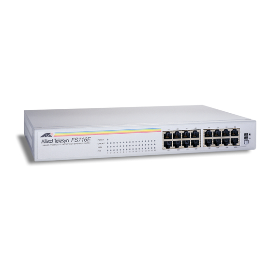
100 meters (328 feet). These ports are capable of auto-negotiating at 10 or 100 Mbps and feature half- and full-duplex operation. The AT-FS716 and AT-FS724i feature an internal power supply and are designed for desktop or rackmount installation. The AT-FS716E features an external power supply and is designed for desktop use only. -
Page 14: Key Features
RJ-45 100 m (328 ft) AT-FS724i RJ-45 100 m (328 ft) Key Features The AT-FS716 Series and AT-FS724i switches have the following key features: " LEDs for unit and port status " 16 or 24 auto-negotiating 10/100Base-TX ports " Auto MDI/MDI-X on all ports "... -
Page 15: Status Leds
AT-FS716 Series and AT-FS724i Installation Guide Status LEDs Table 2 lists the status LEDs for the AT-FS716 Series and AT-FS724i switches. Table 2 Status LEDs Color Description POWER Green Power is applied to the switch. LINK/ACTIVITY Green A valid link has been established on the port. -
Page 16: Auto Mdi/Mdi-X
However, an end-node operating in full-duplex can send and receive data simultaneously. The best network performance is achieved when an end-node can operate in full-duplex mode. The AT-FS716 Series and AT-FS724i switches can operate in either full- or half-duplex mode. -
Page 17: Network Topologies
AT-FS716 Series and AT-FS724i Installation Guide Network Topologies The AT-FS716 Series and AT-FS724i switches can be used in a variety of network topologies, such as a power workgroup or cascade. Both topologies are described below. Power Workgroup Topology A power workgroup topology, shown in Figure 3, allows each end-node to directly connect to a 10/100Base-TX port on an AT-FS716 switch. -
Page 18: Cascade Topology
Connecting two similar networking devices together is called ‘cascading’. Figure 4 illustrates this topology where Port 24 on the AT-FS724i switch is connected to Port 8 on the AT-FS716 switch. Since Port 24 is wired as auto MDI/MDI-X, a crossover or straight-through Category 5 or better twisted pair cable can be used. -
Page 19: Chapter 2 Installation
Make sure the following items are included in your package. If any item is missing or damaged, contact your Allied Telesyn sales representative for assistance. One AT-FS716, AT-FS716E, or AT-FS724i Fast Ethernet Switch Four protective feet (for desktop use only) This installation guide... -
Page 20: Planning The Installation
Installation Planning the Installation Be sure to observe the following guidelines when planning the installation of your switch. The end-nodes connected to the twisted pair port can operated at either 10 Mbps or 100 Mbps and half- or full-duplex mode. The end-node connected to a port on the switch can be a network adapter card, repeater, router, hub, or another switch. -
Page 21: Reviewing Safety Guidelines
AT-FS716 Series and AT-FS724i Installation Guide Reviewing Safety Guidelines Please review the following safety guidelines before you begin to install the switch. Caution Power to the hub must be sourced only from the adapter. (AT-FS716E) Warning Electrical Shock Hazard: To prevent electrical shock, do not remove the cover. -
Page 22: Installing The Switch On A Table Or Desktop
Installation Installing the Switch on a Table or Desktop If you are rackmounting an AT-FS716 or AT-FS724i switch, refer to “Rackmounting the Switch” on page 11. Note The AT-FS716E switch can only be use on a table or desktop. To install the switch on a table or desktop, perform the following procedure: 1. -
Page 23: Rackmounting The Switch
The switch is now ready for use. Rackmounting the Switch The AT-FS716 and AT-FS724i switches can be used on a desktop or installed in a rack. For desktop installation, refer to “Installing the Switch on a Table or Desktop” on page 10. - Page 24 Installation 3. Attach the rackmounting brackets to each side of the switch using the screws provided. See Figure 7. Figure 7 Attaching the Rackmounting Brackets to the Switch 4. Secure the switch to the rack using 2 screws (not provided) for each side as shown in Figure 8.
-
Page 25: Warranty Registration
AT-FS716 Series and AT-FS724i Installation Guide Note The switch performs a self-diagnostic test upon power up. This takes about 20 seconds to complete. 6. Connect the twisted pair cables to a twisted pair ports on the switch and on the end-nodes. -
Page 27: Chapter 3 Troubleshooting
Chapter 3 Troubleshooting Follow the guidelines below to test and troubleshoot the installation in the event a problem occurs. If the POWER LED is OFF, do the following: " For an external power supply, check to be sure that the power adapter is securely connected to a power outlet and that the power adapter cable is securely connected to the back of the switch. -
Page 29: Technical Specifications
Appendix A Technical Specifications Physical Dimensions: W x D x H AT-FS716/AT-FS716E 330 mm x 203 mm x 44 mm (13.0 in x 8.0 in x 1.73 in) AT-FS724i 440 mm x 174 mm x 41 mm (17.32 in x 6.85 in x 1.61 in) -
Page 30: Electrical Rating
Technical Specifications Electrical Rating Internal Universal Power Supply: AT-FS716/AT-FS724i 100 - 240 V AC, 50/60 Hz, 0.5A input External Power Adapter: AT-FS716E 5 ± 5% V DC, 1.6A maximum Agency Compliance EMI/RFI: AT-FS716/AT-FS716E FCC Class A, EN55022 Class A, VCCI Class A, CISPR Class A... -
Page 31: Pinout Assignments
AT-FS716 Series and AT-FS724i Installation Guide Pinout Assignments Figure 9 shows the pin assignments of the RJ-45 connector. Pin 8 Pin 1 Figure 9 RJ-45 Connector Table 4 lists the 100Base-TX connector pins and their signals when the port is operating in either MDI or MDI-X configuration. -
Page 33: Translated Safety And Emission Information
Appendix B Translated Safety and Emission Information Important: This appendix contains multiple-language translations for the safety statements in this guide. Wichtig: Dieser Anhang enthält Übersetzungen der in diesem Handbuch enthaltenen Sicherheitshinweise in mehreren Sprachen. Vigtigt: Dette tillæg indeholder oversættelser i flere sprog af sikkerhedsadvarslerne i denne håndbog. -
Page 34: For At-Fs716 And At-Fs716E
Translated Safety and Emission Information For AT-FS716 and AT-FS716E Standards: This product meets the following standards. U.S. Federal Communications Commission Radiated Energy Note: This equipment has been tested and found to comply with the limits for a Class A digital device pursuant to Part 15 of FCC Rules. These limits are designed to provide reasonable protection against harmful interference when the equipment is operated in a commercial environment. - Page 35 AT-FS716 Series and AT-FS724i Installation Guide RFI Emissie EN55022 Klasse A Waarschuwing: Binnenshuis kan dit product radiostoring veroorzaken, in welk geval de. Stroom mag alleen via de adapter naar het apparaat toegevoerd worden. (AT- FS716E) Emission d’interférences radioélectriquesEN55022 Classe A Mise En Garde: dans un environnement domestique, ce produit peut provoquer des interférences radioélectriques.
-
Page 36: For At-Fs724I
Translated Safety and Emission Information La energía para el dispositivo central o “hub” debe provenir únicamente del adaptador. (AT-FS716E) Radiostörning EN55022 Klass A Varning: Denna produkt kan ge upphov till radiostörningar i hemmet, vilket kan tvinga användaren till att vidtaga erforderliga åtgärder. Endast anslutningsenheten får vara kraftkälla till centralen. -
Page 37: All Models
AT-FS716 Series and AT-FS724i Installation Guide All Models Immunity EN55024 Electrical Safety TUV-EN60950, UL 1950 (UL/cUL) Safety Electrical Notices Warning: Electric Shock Hazard To prevent ELECTRIC shock, do not remove cover. No user-serviceable parts inside. This unit contains HAZARDOUS VOLTAGES and should only be opened by a trained and qualified technician. - Page 38 Translated Safety and Emission Information Installation Steckbares Gerät: Die Anschlußbuchse sollte in der Nähe der Einrichtung angebracht werden und leicht zugänglich sein.” Automatische Spannungseinstellung Dieses Gerät stellt sich automatisch auf die auf dem Etikett aufgeführten Spannungswerte ein. Geräte Der Klasse 1 DIESE GERÄTE MÜSSEN GEERDET SEIN.
- Page 39 AT-FS716 Series and AT-FS724i Installation Guide Alle Lande: Installation af produktet skal ske i overensstemmelse med lokal og national lovgivning for elektriske installationer. Normen: Dit product voldoet aan de volgende veiligheidsnormen. Immuniteit EN55024 Electrische Veiligheid TUV-EN60950, UL 1950 (UL/cUL) Veiligheid...
- Page 40 Translated Safety and Emission Information Installation Equipement Pour Branchement Electrique, la prise de sortie doit être placée près de l’équipement et facilement accessible”. Réglage De Tension Automatique Électrique Ce matériel peut s’ajuster automatiquement sur n’importe quelle tension comprise dans la plage indiquée sur l’étiquette. Équipement De Classe 1 Électrique CE MATÉRIEL DOIT ÊTRE MIS A LA TERRE.
- Page 41 AT-FS716 Series and AT-FS724i Installation Guide Kaikki Maat: Asenna tuote paikallisten ja kansallisten sähköturvallisuusmääräysten mukaisesti. Standard: questo prodotto soddisfa i seguenti standard di sicurezza. Immunità EN55024 Sicurezza elettrica TUV-EN60950, UL 1950 (UL/cUL) Norme Di Sicurezza Avvertenze Elettriche Attenzione: PERICOLO DI SCOSSE ELETTRICHE Per evitare SCOSSE ELETTRICHE non asportare il coperchio.
- Page 42 Translated Safety and Emission Information Fare For Lynnedslag Fare: ARBEID IKKE på utstyr eller KABLER i TORDENVÆR. Installasjon Utstyr For Stikkontakt. Stikkontakten skal monteres i nærheten av utstyret og skal være lett tilgjengelig.” Elektrisk—Auto Spenningstilpasning Dette produktet vil automatisk bli tilpasset hvilken som helst strømspenning i de områdene som vises på...
- Page 43 AT-FS716 Series and AT-FS724i Installation Guide Temperatura De Funcionamento: Este produto foi projetado para uma temperatura ambiente máxima de 40 graus centígrados. Todos Os Países: Instale o produto de acordo com as normas nacionais e locais para instalações elétricas. Normas: este producto cumple con las siguientes normas de seguridad.
- Page 44 Translated Safety and Emission Information Normer: Denna produkt uppfyller följande säkerhetsnormer. Immunitet EN55024 Elsäkerhet TUV-EN60950, UL 1950 (UL/cUL) Säkerhet Tillkännagivanden Beträffande Elektricitetsrisk: RISK FÖR ELEKTRISK STÖTFör att undvika ELEKTRISK stöt, ta ej av locket. Det finns inga delar inuti som behöver underhållas. Denna apparat är under HÖGSPÄNNING och får endast öppnas av en utbildad kvalificerad tekniker.
Need help?
Do you have a question about the AT-FS716 and is the answer not in the manual?
Questions and answers