Sign In
Upload
Download
Table of Contents
Contents
Add to my manuals
Delete from my manuals
Share
URL of this page:
HTML Link:
Bookmark this page
Add
Manual will be automatically added to "My Manuals"
Print this page
×
Bookmark added
×
Added to my manuals
Manuals
Brands
Allied Telesis Manuals
Switch
AT-GS950
Installation manual
Allied Telesis AT-GS950 Installation Manual
Gigabit ethernet smart switch
Hide thumbs
Also See for AT-GS950
:
Datasheet
(2 pages)
,
Datasheet
(2 pages)
1
2
3
4
Table Of Contents
5
6
7
8
9
10
11
12
13
14
15
16
17
18
19
20
21
22
23
24
25
26
27
28
29
30
31
32
33
34
35
36
37
38
39
40
41
42
43
44
45
46
page
of
46
Go
/
46
Contents
Table of Contents
Troubleshooting
Bookmarks
Table of Contents
Gigabit Ethernet
Installation Guide
Electrical Safety and Emissions Standards
Translated Safety Statements
Table of Contents
Preface
Safety Symbols Used in this Document
Table 1. Safety Symbols
Where to Find Web-Based Guides
Contacting Allied Telesis
Online Support
Email and Telephone Support
Warranty
Returning Products
Sales or Corporate Information
Management Software Updates
Chapter 1: Overview
Features
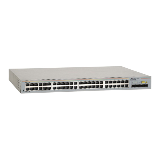
Front and Back Panels
Figure 1. AT-GS950/48 and Front and Back Panels
Ports
Twisted Pair Ports
SFP Ports
Leds
Power LED
Port Leds
Figure 2. Power LED
Figure 3. Port Leds
Table 2. Power LED
Table 3. 10/100Base-T POE Port Leds
Power Supply
Ethernet Switching Basics
MAC Address Table
Duplex Mode
Store and Forward
Back Pressure and Flow Control
Network Topologies
Power Workgroup Topology
Figure 4. Power Workgroup Topology
Collapsed Backbone
Figure 5. Collapsed Backbone - Hub Topology
Chapter 2: Installation
Reviewing Safety Precautions
Selecting a Site for the Switch
Cabling
Table 4. Twisted Pair Cabling and Distances
Unpacking the Switch
Installing the Switch on a Desktop
Figure 6. Attaching the Rubber Feet
Installing the Switch in a Rack
Figure 7. Attaching the Rack-Mount Bracket
Figure 8. Mounting the Switch on the Rack
Installing an Optional SFP Transceiver
Figure 9. Removing the Dust Plug from the SFP Slot
Figure 10. Inserting the SFP
Cabling and Powering on the Switch
Connecting the Twisted Pair Cables
Connecting the Fiber Optic Cables
Figure 11. Connecting the Twisted Pair Data Cables
Powering on the Switch
Figure 12. Removing the Dust Plug from the SFP
Figure 13. Connecting the Fiber Optic Cable
Figure 14. Plugging in the AC Power Cord
Starting a Management Session
Figure 15. AT-S87 Management Software Main Page
Chapter 3: Troubleshooting
Appendix A: Technical Specifications
Physical Specifications
Environmental Specifications
Power Specifications
Safety and Electromagnetic Emissions Certifications
Advertisement
Quick Links
Download this manual
Gigabit Ethernet
Smart Switch
AT-GS950/48
Installation Guide
613-000535 Rev. B
Table of
Contents
Previous
Page
Next
Page
1
2
3
4
5
Advertisement
Table of Contents
Need help?
Do you have a question about the AT-GS950 and is the answer not in the manual?
Ask a question
Questions and answers
Related Manuals for Allied Telesis AT-GS950
Switch Allied Telesis AT-GS950/24 Datasheet
16 port gigabit websmart switch (2 pages)
Switch Allied Telesis AT-GS950 Datasheet
48 port gigabit websmart switch (2 pages)
Switch Allied Telesis AT-GS950/16 Datasheet
16 port gigabit websmart switch (2 pages)
Switch Allied Telesis AT-GS950/24 Datasheet
24 port gigabit websmart switch (2 pages)
Switch Allied Telesis AT-GS950/8 Datasheet
8 port gigabit websmart switch (2 pages)
Switch Allied Telesis AT-GS950/8POE Datasheet
8 port gigabit fanless poe websmart switch (2 pages)
Switch Allied Telesis AT-GS950/48 Installation Manual
Gigabit ethernet websmart switch (60 pages)
Switch Allied Telesis AT-GS950/48 User Manual
Gigabit ethernet poe+ switch (378 pages)
Switch Allied Telesis AT-GS950/48 User Manual
Gigabit ethernet switch (406 pages)
Switch Allied Telesis AT-GS950/48 User Manual
(410 pages)
Switch Allied Telesis GS950 PS Series Product Information
Gs950 ps series gigabit websmart poe+ edge switches (2 pages)
Switch Allied Telesis GS950 PS Series Product Information
Gs950 ps series gigabit websmart poe+ edge switches (3 pages)
Switch Allied Telesis AT-GS950/16PS User Manual
Gigabit ethernet poe+ switch (386 pages)
Switch Allied Telesis AT-GS950/10PS User Manual
Gigabit ethernet poe switches (86 pages)
Switch Allied Telesis AT-GS950/28PS Installation Manual
Gigabit ethernet poe+ switches (72 pages)
Switch Allied Telesis AT-GS900/16 Installation Manual
Gigabit ethernet switches (59 pages)
This manual is also suitable for:
At-gs948
Table of Contents
Print
Rename the bookmark
Delete bookmark?
Delete from my manuals?
Login
Sign In
OR
Sign in with Facebook
Sign in with Google
Upload manual
Upload from disk
Upload from URL


Need help?
Do you have a question about the AT-GS950 and is the answer not in the manual?
Questions and answers