
Related Manuals for ADTRAN 1748F


Summary of Contents for ADTRAN 1748F
- Page 1 ADTRAN 1748F Switch Hardware Installation Guide 1700558F1 ADTRAN 1748F 61700558F1-34B December 2016...
- Page 2 To the Holder of the Manual The contents of this manual are current as of the date of publication. ADTRAN reserves the right to change the contents without prior notice. In no event will ADTRAN be liable for any special, incidental, or consequential damages or for commercial losses even if ADTRAN has been advised thereof as a result of issue of this publication.
- Page 3 ADTRAN 1748F Switch Conventions Conventions Notes provide additional useful information. Cautions signify information that could prevent service interruption or damage to the equipment. Warnings provide information that could prevent injury or endangerment to human life. 61700558F1-34B Copyright © 2016 ADTRAN, Inc.
- Page 4 These units contain no user-serviceable parts. They should only be serviced by qualified service personnel. Additional safety guidelines, such as Waste Electrical and Electronic Equipment (WEEE), are given in the document NetVanta Safety and Regulatory Information available at https://supportforums.adtran.com. Save These Important Safety Instructions Copyright © 2016 ADTRAN, Inc. 61700558F1-34B...
- Page 5 Department of Communications. Cet appareil numérique respecte les limites de bruits radioelectriques applicables aux appareils numériques de Class A prescrites dans la norme sur le materiel brouilleur: “Appareils Numériques,” NMB-003 edictee par le ministre des Communications. 61700558F1-34B Copyright © 2016 ADTRAN, Inc.
- Page 6 Denial of Service (DoS) attacks, loss or theft of data, and the unauthorized or illegal use of said equipment. ADTRAN OFFERS NO WARRANTIES, EITHER EXPRESSED OR IMPLIED, REGARDING THE PREVENTION, DETECTION, OR DETERRENCE OF TOLL FRAUD, NETWORKING ATTACKS, OR UNAUTHORIZED, ILLEGAL, OR IMPROPER USE OF ADTRAN EQUIPMENT OR SOFTWARE.
-
Page 7: Table Of Contents
Installation ..............41 61700558F1-34B Copyright © 2016 ADTRAN, Inc. - Page 8 Table of Contents ADTRAN 1748F Switch Copyright © 2016 ADTRAN, Inc. 61700558F1-34B...
- Page 9 ADTRAN 1748F Front Panel Layout ........
- Page 10 List of Figures ADTRAN 1748F Switch Copyright © 2016 ADTRAN, Inc. 61700558F1-34B...
- Page 11 Troubleshooting Chart ............41 61700558F1-34B Copyright © 2016 ADTRAN, Inc.
- Page 12 List of Tables ADTRAN 1748F Switch Copyright © 2016 ADTRAN, Inc. 61700558F1-34B...
-
Page 13: Introduction
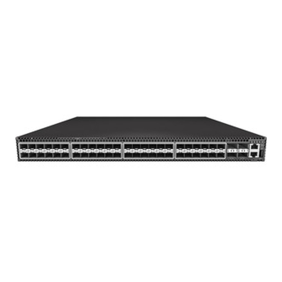
Switch Overview The ADTRAN 1748F switch is a high-performance top-of-rack switch, designed for campus local area network (LAN) and data center operating environments. The switch provides 48 10G Ethernet Small Form Factor Pluggable Plus (SFP+) transceiver slots, four 40G Quad-SFP+ (QSFP+) ports, and two 1G RJ-45 ports. The switch also includes replaceable dual power supply units and a fan tray module. -
Page 14: Figure 2. Adtran 1748F Rear Panel Layout
For more information on port status LED indicators, refer to Understanding the Port Status LEDs on page ADTRAN 1748F Rear Panel Design The ADTRAN 1748F rear panel is shown below. Figure 2. ADTRAN 1748F Rear Panel Layout Copyright © 2016 ADTRAN, Inc. 61700558F1-34B... -
Page 15: Product Specifications
• 400 Watts at 240 V/100 V per module Power Consumption • 165 Watts maximum Out-of-Band Management • RS-232 RJ-45 console port In-Band Management • SSH, Telnet, or SNMP Software Loading • FTP/TFTP in-band 61700558F1-34B Copyright © 2016 ADTRAN, Inc. -
Page 16: Deployment
Most rack-mounted blade servers draw cool air from the front and expel hot air at the rear. The top-of-rack switch includes power supply units and a fan tray module that have a front-to-back (F2B) airflow direction that maintains cool aisles in the data center. Copyright © 2016 ADTRAN, Inc. 61700558F1-34B... -
Page 17: Figure 3. F2B Airflow Cooling
This enables various deployment options for the switch in the data center. Hot Aisle Cool Aisle ToR Switch Servers Front of Rack Rear of Rack Figure 4. B2F Airflow Cooling 61700558F1-34B Copyright © 2016 ADTRAN, Inc. -
Page 18: Unit Installation
Supplying Power to the Unit on page 22 Shipping Contents Each ADTRAN 1748F Switch unit is shipped in its own cardboard shipping carton. Open each carton carefully, and avoid deep penetration into the carton with sharp objects. After unpacking the unit, inspect it for possible shipping damage. If the equipment has been damaged in transit,... -
Page 19: Figure 5. Attach Mounting Brackets
Wear an anti-static wrist strap or take other suitable measures to prevent electrostatic discharge when handling this equipment. • The ADTRAN 1748F is intended to be installed, maintained, and serviced by qualified service personnel only and should be installed in a restricted access location as described in UL/IEC 60950-1. -
Page 20: Switch Cooling Requirements
F2B or B2F airflow direction. For proper switch cooling, all installed modules must have a matching airflow direction.The following figure shows the airflow through the switch. B2F Airflow F2B Airflow Figure 7. Switch Cooling Copyright © 2016 ADTRAN, Inc. 61700558F1-34B... -
Page 21: Replacing The Fan Tray
The fan speed is dynamically controlled as a function of temperature: the higher the internal temperature, the faster the speed of the fans. The fan tray module does not include LED indicators. Label Indicates Airflow Direction Figure 8. Fan Tray 61700558F1-34B Copyright © 2016 ADTRAN, Inc. -
Page 22: Supplying Power To The Unit
All installed modules must have a matching airflow direction. That is, all modules must have a front-to-back (F2B) airflow direction, or all modules must have a back-to-front (B2F) airflow direction. The airflow direction of PSUs and fan trays is indicated by labels on the modules. Copyright © 2016 ADTRAN, Inc. 61700558F1-34B... -
Page 23: Figure 9. Ac Power Supply Module
Green (solid) External AC power is connected to the module. Grounding the Chassis The switch chassis must be connected to ground to ensure proper operation and to meet electromagnetic interference (EMI) and safety requirements. 61700558F1-34B Copyright © 2016 ADTRAN, Inc. -
Page 24: Figure 10. Grounding Terminal
Then attach the grounding wire to the ground point on the rack. Connecting to AC Power To supply AC power to the switch, first verify that the external AC power supply can provide 100 to 240 VAC, 50-60 Hz, 3 A minimum. Copyright © 2016 ADTRAN, Inc. 61700558F1-34B... -
Page 25: Figure 11. Ac Psu And Power Socket
Check the LED indicators on the PSU and switch front panel as the unit is powered on to verify that power is being received. If not, recheck the PSU and power cord connections at the AC supply source and PSU. If you have installed a second PSU, repeat steps 2 to 4. 61700558F1-34B Copyright © 2016 ADTRAN, Inc. -
Page 26: Port Connections
Use sequential numbers for cables that originate from the same equipment. • Differentiate between racks by naming accordingly. • Label each separate piece of equipment. • Display a copy of your equipment map, including keys to all abbreviations at each equipment rack. Copyright © 2016 ADTRAN, Inc. 61700558F1-34B... -
Page 27: Understanding The Port Status Leds
1000 Mbps Ethernet SFP transceivers • SFP/SFP+/QSFP+ transceivers are hot-swappable. The switch does not need to be powered off before installing or removing a transceiver. • SFP/SFP+/QSFP+ transceivers are not provided in the switch package. 61700558F1-34B Copyright © 2016 ADTRAN, Inc. -
Page 28: Connecting To Twisted-Pair Copper Ports
Connecting to Twisted-Pair Copper Ports The RJ-45 management port on the switch supports automatic MDI/MDI-X pinout configuration, so you can use standard straight-through twisted-pair cables to connect to any other network device (PCs, servers, switches, routers, or hubs). Copyright © 2016 ADTRAN, Inc. 61700558F1-34B... -
Page 29: Table 4. Maximum Twisted-Pair Copper Cable Lengths
PCs, switches, or hubs. In straight-through cable, pins 1, 2, 3, and 6, at one end of the cable, are connected straight through to pins 1, 2, 3, and 6 at the other end of the cable. RJ-45 Pin Numbers 61700558F1-34B Copyright © 2016 ADTRAN, Inc. -
Page 30: Figure 14. Rj-45 Connector
1000BASE-T is a simple test of the cable installation to be sure that it complies with the IEEE 802.3-2008 standards. Connection Procedure The switch has one 10/100/1000BASE-T port for dedicated management access. Making a connection to this port is described in Connecting to the Management Port on page Copyright © 2016 ADTRAN, Inc. 61700558F1-34B... -
Page 31: Connecting To Sfp/Sfp+ Fiber Optic Ports
• When selecting a fiber SFP/SFP+ device, considering safety, please make sure that it can function at a temperature that is not less than the recommended maximum operational temperature of the product. You must also use an approved Laser Class 1 SFP/SFP+ transceiver. 61700558F1-34B Copyright © 2016 ADTRAN, Inc. -
Page 32: Connecting To Qsfp+ Fiber Optic Ports
The switch includes four slots for 40 Gigabit Ethernet QSFP+ fiber-optic transceivers. Note that 40G fiber optic ports can provide either one 40 Gbps full duplex link, four independent 10G fiber optic links. Connecting a 40G QSFP+ port to four 10G SFP+ ports requires the use of a breakout cable. Copyright © 2016 ADTRAN, Inc. 61700558F1-34B... -
Page 33: Table 9. Maximum 40 Gigabit Ethernet Fiber Cable Lengths
(typically a few inches). Use cable ties to bundle cables together and secure coiled loops of excess cable. Do not let cables hang free supporting their own weight or pull in any way that puts stress on the connectors. 61700558F1-34B Copyright © 2016 ADTRAN, Inc. -
Page 34: Dac Connections
Table 11. Maximum 40GBASE-CR4 40 Gigabit Ethernet Cable Lengths Cable Type Cable Lengths Connector Pre-terminated Direct Attach Cable 1 m (3.28 ft) QSFP+ (DAC) — (twinaxial copper cable) 2 m (6.56 ft) 3 m (9.8 ft) 5 m (16.4 ft) Copyright © 2016 ADTRAN, Inc. 61700558F1-34B... -
Page 35: Figure 17. Making Dac Connections
Check that the Link LED on the switch turns on green to indicate that the connection is valid. Connecting a 40G QSFP+ port to four 10G SFP+ ports requires the use of a breakout DAC cable. 10G SFP+ DAC Cable Figure 17. Making DAC Connections 61700558F1-34B Copyright © 2016 ADTRAN, Inc. -
Page 36: Switch Management
The switch includes a display panel of key system LED indicators. The LEDs, which are located on the front panel, are shown below and described in the following table. System Status LEDs Figure 18. System LEDs Copyright © 2016 ADTRAN, Inc. 61700558F1-34B... -
Page 37: Connecting To The Management Port
Port has established a valid network connection Green (flashing) There is activity on the port. Speed Green (solid) There is a valid 10/100 Mbps link. Amber (solid) There is a valid 1000 Mbps link. 61700558F1-34B Copyright © 2016 ADTRAN, Inc. -
Page 38: Connecting To The Console Port
To connect to notebooks or other PCs that do not have a DB-9 COM port, use a USB to male DB-9 adapter cable (not included with the switch). Console Port Figure 20. Console Port Copyright © 2016 ADTRAN, Inc. 61700558F1-34B... -
Page 39: Figure 21. Console Port Connection
Configure the PC’s COM port required settings using VT-100 terminal emulator software (such as HyperTerminal) running on the management PC. Log in to the command-line interface (CLI) using default settings: User admin, Password null (there is no default password). 61700558F1-34B Copyright © 2016 ADTRAN, Inc. -
Page 40: Connecting To The Usb Port
Use a long thin object, such as the end of a paper clip, to press the reset button. One push of the button restarts the system software using default values. Reset Button Figure 23. Reset Button Copyright © 2016 ADTRAN, Inc. 61700558F1-34B... -
Page 41: Troubleshooting
Verify that all system components have been properly installed. If one or more components appear to be malfunctioning (such as the power cord or network cabling), test them in an alternate environment where you are sure that all the other components are functioning properly. 61700558F1-34B Copyright © 2016 ADTRAN, Inc. - Page 42 Troubleshooting ADTRAN 1748F Switch Copyright © 2016 ADTRAN, Inc. 61700558F1-34B...
Need help?
Do you have a question about the 1748F and is the answer not in the manual?
Questions and answers