Weider 9000 User Manual
Uk manual
Hide thumbs
Also See for 9000:
- Gebruiksaanwijzing (28 pages) ,
- Manuel de l'utilisateur (28 pages) ,
- Bedienungsanleitung (28 pages)
Table of Contents
Advertisement
Model No. WEEMBE39221
Serial No.
Write the serial number in the
space above for reference.
Serial Number Decal (under seat)
QUESTIONS?
As a manufacturer, we are com-
mitted to providing complete
customer satisfaction. If you
have questions, or if there are
missing or damaged parts,
please call:
08457 089 009
Or write:
ICON Health & Fitness, Ltd.
Unit 4
Revie Road Industrial Estate
Revie Road
Beeston
Leeds
LS11 8JG
UK
csuk@iconeurope.com
CAUTION
Read all precautions and instruc-
tions in this manual before
using this equipment. Save this
manual for future reference.
USER'S MANUAL
Visit our website at
www.iconeurope.com
Advertisement
Table of Contents

Related Manuals for Weider 9000


Summary of Contents for Weider 9000
- Page 1 Model No. WEEMBE39221 Serial No. USER’S MANUAL Write the serial number in the space above for reference. Serial Number Decal (under seat) QUESTIONS? As a manufacturer, we are com- mitted to providing complete customer satisfaction. If you have questions, or if there are missing or damaged parts, please call: 08457 089 009...
-
Page 2: Table Of Contents
TABLE OF CONTENTS WARNING DECAL PLACEMENT ............. 2 IMPORTANT PRECAUTIONS . -
Page 3: Important Precautions
IMPORTANT PRECAUTIONS WARNING: To reduce the risk of serious injury, read the following important precautions before using the weight bench. 1. Read all instructions in this manual before 10. Always set both weight rests and both safety using the weight bench. Use the weight spotters at the same height. -
Page 4: Before You Begin
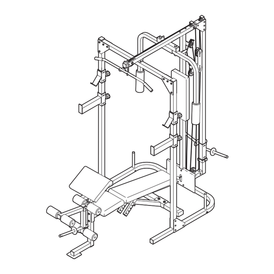
(see the front cover of this manual for the WEIDER ® 9000 weight bench will help you to the location). achieve the specific results you want. Before reading further, please review the drawing... -
Page 5: Assembly
ASSEMBLY • As you assemble the weight bench, make sure all Make Things Easier for Yourself parts are oriented as shown in the drawings. Everything in this manual is designed to ensure • For help identifying small parts, use the PART that the weight bench can be assembled suc- IDENTIFICATION CHART in the centre of this cessfully by anyone. - Page 6 2. Slide the Centre Upright (5) onto the M10 x 60mm Carriage Bolts (50) in the Right and Left Bases (1, 2). Make sure that the Centre Upright is turned so the indicated bracket is on the Bracket side shown. Hand tighten two M10 Nylon Locknuts (49) onto the Bolts.
- Page 7 4. Attach one of the Uprights (3) to the Right Base (1) with four M10 x 68mm Bolts (46), two Support Plates (14), and four M10 Nylon Locknuts (49). Do not tighten the Nylon Locknuts yet. Repeat this step with the other Upright (not shown) and the Left Base (not shown).
- Page 8 7. Slide the Carriage Stop (19) onto the Rear Upright (6). Make sure that the Carriage Stop is oriented so the Carriage Stop Bushing (20) and the indicated hole are in the positions shown. Attach the Carriage Stop to the hole near the bottom of the Rear Upright with an M8 x 70mm Bolt (58) and an M8 Nylon Locknut (48).
- Page 9 11. Identify the Right and Left Butterfly Arms (11, 12) by noting the positions of the welded brackets. Bracket Press two 45mm Square Inner Caps (42) into the ends of the Left Butterfly Arm (12). Wet the bot- Lubricate tom end of the Butterfly Arm with soapy water. Axle Slide a Large Foam Pad (18) onto the end of the Welded...
- Page 10 14. Wrap the Butterfly Cable (32) around a “V”-Pulley (25). Attach the Pulley and a Large Cable Trap (27) to the bracket on the Centre Upright (5) with an M10 x 60mm Bolt (47) and an M10 Nylon Bracket Locknut (49). 15.
- Page 11 18. Identify the High Cable (31), which is the shorter of the two remaining cables. Route the eyelet end of the Cable up through the indicated hole in the Top Frame (8). Wrap the High Cable (31) around a 90mm Pulley (24).
- Page 12 22. Attach the High Cable (31) to the M10 x 19mm Bolt (not shown) in the bracket on the Weight Carriage (10) with an M10 Nylon Locknut (49). Bracket 23. Locate the Low Cable (33). Route the eyelet end of the Cable through the hole in the Foot Plate (9) and through the Centre Upright (5).
- Page 13 26. Wrap the Low Cable (33) around a 90mm Pulley (24). Attach the Pulley and a Cable Trap (26) to the second hole from the bottom of the two Pulley Plates (28) with an M10 x 45mm Bolt (57) and an M10 Nylon Locknut (49).
- Page 14 Bench Assembly 29. Press two 51mm x 76mm Outer Caps (79) onto the Stabiliser (62). Attach the Stabiliser to the Bench Frame (63) with two M10 x 60mm Carriage Bolts (50) and two M10 Nylon Locknuts (49). 30. Press three 50mm Square Inner Caps (43) into the Front Leg (64).
- Page 15 33. Orient the Seat (70) with the wide end on the side shown. Attach the Seat to the Bench Frame (63) with four M6 x 16mm Bolts (80). Wide 34. Press three 45mm Square Inner Caps (42) into the Leg Lever (66). Attach the Weight Tube (65) to the Leg Lever (66) with an M8 x 58mm Bolt (41), two M8 Washers (53), a 13mm x 10mm Spacer (75), and an M8...
-
Page 16: Adjustments
37. Attach the Curl Pad (84) to the Curl Post (83) with two M6 x 16mm Bolts (80). 38. Make sure that all parts have been properly tight- ened. The use of the remaining parts will be explained in ADJUSTMENTS, below. ADJUSTMENTS This section explains how to adjust the weight bench. - Page 17 ATTACHING THE LAT BAR TO THE HIGH PULLEY STATION OR THE LOW PULLEY STATION To use the high or low pulley station, attach the Lat Bar (73) to the High Cable (31) or the Low Cable (not shown) using a Cable Clip (30). The Row Bar (not shown) can be attached in the same manner.
- Page 18 USING THE CURL PAD Remove the 50mm Square Inner Cap (43) from the Front Leg (64). Align a hole in the Curl Post (83) with the hole in the Front Leg (64). Secure the Curl Post with the Curl Knob (4). Be sure the Knob is fully tightened. Note: When not using the Curl Pad (84), store it away from the weight bench.
-
Page 19: Weight Resistance Chart
WEIGHT RESISTANCE CHART This chart shows the approximate weight resistance at each weight station. The column labeled “WEIGHT” refers to the amount of weight, in pounds, placed on the weight carriage. The weight resistance shown for the butterfly arm station is for each butterfly arm. Note: The actual resistance at each station may vary due to friction between the cables, pulleys, and weight carriage. -
Page 20: Cable Diagrams
CABLE DIAGRAMS The cable diagrams below show the proper routing of the High Cable (31), the Butterfly Cable (32), and the Low Cable (33). Use the diagram to make sure that the cables and the cable traps have been assembled correctly. If the cables have not been correctly routed, the weight bench will not function properly and damage may occur. -
Page 21: Troubleshooting And Maintenance
TROUBLESHOOTING AND MAINTENANCE Make sure all parts are properly tightened each time you use the weight bench. Replace any worn parts immedi- ately. The weight bench can be cleaned using a damp cloth and mild non-abrasive detergent. Do not use solvents. TIGHTENING THE CABLES Woven cable, the type of cable used on the weight rack, can stretch slightly when it is first used. -
Page 22: Exercise Guidelines
EXERCISE GUIDELINES THE FOUR BASIC TYPES OF WORKOUTS PERSONALISING YOUR EXERCISE PROGRAM Muscle Building Determining the exact length of time for each workout, To increase the size and strength of your muscles, as well as the number of repetitions or sets completed, push them close to their maximum capacity. - Page 23 Rest for a short period of time after each set. The slowly as you stretch and do not bounce. Ease into ideal resting periods are: each stretch gradually and go only as far as you can • Rest for three minutes after each set for a muscle without strain.
-
Page 24: Ordering Replacement Parts
• the KEY NUMBER and DESCRIPTION of the part(s) (see the PART LIST and the EXPLODED DRAWING in the centre of this manual) WEIDER is a registered trademark of ICON Health & Fitness, Inc. Part No. 197080 R0303A Printed in China © 2003 ICON Health & Fitness, Inc. - Page 25 PART IDENTIFICATION CHART Refer to the drawings below to identify small parts used in assembly. The number in parentheses by each draw- ing is the key number of the part, from the PART LIST in the centre of this manual. Note: Some small parts may have been pre-attached.
- Page 26 19mm Round Inner Cap (81) 51mm x 76mm Outer Cap (79) 25mm Round Inner Cap (45) 25mm x 50mm Inner Cap (82) 13mm x 12mm Spacer (38) 50mm Square Inner Cap (43) 15mm x 8mm Spacer (55) 13mm x 10mm Spacer (75) 15mm x 13mm Spacer (39) 15mm x 10mm Spacer (40) 45mm Square Inner Cap (42)
- Page 27 PART LIST—Model No. WEEMBE39221 R0303A Key No. Qty. Description Key No. Qty. Description Right Base 25mm Round Inner Cap Left Base M10 x 68mm Bolt Upright M10 x 60mm Bolt Curl Knob M8 Nylon Locknut Centre Upright M10 Nylon Locknut Rear Upright M10 x 60mm Carriage Bolt Crossbar...
- Page 28 EXPLODED DRAWING—Model No. WEEMBE39221 R0303A...
Need help?
Do you have a question about the 9000 and is the answer not in the manual?
Questions and answers