AOR AR-2300 Operating Manual
Black-box receiver i/q special edition
Hide thumbs
Also See for AR-2300:
- Operating manual (67 pages) ,
- Operating manual (24 pages) ,
- Operating manual (67 pages)

Subscribe to Our Youtube Channel
Related Manuals for AOR AR-2300


Summary of Contents for AOR AR-2300
- Page 1 AR2300 BLACK-BOX RECEIVER “I/Q SPECIAL EDITION” OPERATING MANUAL OCTOBER 1, 2021 AOR, LTD. www.aorja.com...
- Page 3 INTRODUCTION Thank you for purchasing the AR2300. AR2300 is a high-end black-box type receiver with wide band coverage between 40kHz and 3.15GHz. Some of its outstanding features are: 1) Digital signal processing: Input signals after the 45.05MHz IF are converted from analog to digital by a DSP processor. There is no AGC in the analog processing unit, as all processing, including AGC, is done by DSP.
- Page 4 Immediately turn OFF the receiver power and remove the power cable from the receiver if it emits an abnormal odor, sound or smoke. Contact your AOR dealer or distributor for advice. DO NOT put the receiver on an unstable place where the receiver may suddenly move or fall. This could cause an injury or damage the receiver.
-
Page 5: Table Of Contents
TABLE OF CONTENTS Supplied items ........................... 1 Front/rear panel description ...................... 2 2.1. Front panel ..........................2 2.2. Rear panel........................... 3 Preparing for PC control (Controlsoft: Full receiver control & memory management) ..... 5 3.1. PC requirements ......................... 5 3.2. Connecting the receiver to the PC .................... -
Page 6: Supplied Items
A list of optional accessories is available at: http://www.aorja.com/accessories/receiver_accessories.html The full control command set pdf for system integrators can be downloaded at: http://www.aorja.com/support/manuals2/AR2300_command_list.html AOR software and utilities are listed at: http://www.aorja.com/support/software.html A list of 3 party software solutions is available at:... -
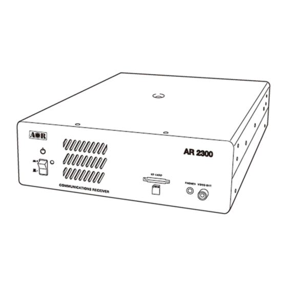
Page 7: Front/Rear Panel Description
2. FRONT/REAR PANEL DESCRIPTION 2.1. Front panel If you need to disconnect the AC power adapter, make sure that the receiver is shut ① Power switch down before. ② Status LED Green: Power on and receiving, Orange/yellow: Stand-by, Not lit: Off To mute the speaker audio while setting up the receiver and control software, simply ③... -
Page 8: Rear Panel
2.2. Rear panel ① ANT 1 Type N socket (50Ω) for frequencies over 25MHz only. ② ANT2/HF Type N socket (50Ω) for all frequencies, including HF. SMA type socket (50Ω) ③ 10MHz IN External reference clock input of 10MHz (2dBm±2dB). When a valid 10MHz is entered, it automatically switches to that external input. - Page 9 Φ3.5mm monaural jack (Up to 2W with 8Ω load) ⑧ SP OUT To connect to an external speaker. Φ3.5mm stereo jack (600Ω -10dBm) To connect to an external recording device, or an audio amplifier. Can be ⑨ LINE OUT switched to output a 12kHz wide analog I/Q signal. In dual-band reception, the main frequency is audible at the right side and the sub-frequency at the left side.
-
Page 10: Preparing For Pc Control (Controlsoft: Full Receiver Control & Memory Management)
3. PREPARING FOR PC CONTROL The supplied AR2300 CONTROLSOFT software features complete receiver control, audio recording/playback and memory bank management for the AR2300 receiver. 3.1 PC requirements Minimum PC system: Supported OS: Windows 7/8.1/10 2GHz Dual Core CPU ... - Page 11 4. After Windows has automatically downloaded and installed the driver, Device Manager will list it as pictured: The auto-assigned COM number depends on your PC configuration. If manual USB driver installation is required, you will find it in the supplied USB key in the following directory: (your USB key) >...
-
Page 12: Control Software Operation
4. CONTROL SOFTWARE OPERATION 4.1 Connecting power Connect the supplied AC power adapter. If using another power supply, make sure it provides DC10.7V〜16V with at least 2 A of power. 4.2 Power on Push the power switch on the receiver’s front panel. The LED will turn orange/yellow, indicating the stand-by mode. -
Page 13: Software Windows Description
4.4 Software windows description Any or all of the following windows can be displayed. Main Control Spectrum display / Menu bar / database Ctrl1 S-Meter Ctrl2 Mode etc. Ctrl3 AF, RF, SQL control Ctrl4 FFT control Ctrl5 Option settings Ctrl6 Frequency panel In the menu bar, go to WINDOW to select your choice of windows to display. -
Page 14: Main Control Window Description
4.4.1 MAIN CONTROL WINDOW DESCRIPTION FREQUENCY (Min.: 0000.040000 MHz, max.: 3150.000000 MHz) Change the receive frequency by either: -Hovering with the mouse over each digit and scrolling the mouse wheel up or down. -Entering the frequency via the PC keyboard + ENTER key for MHz. -
Page 15: Spectrum Display Description
4.4.2 SPECTRUM DISPLAY DESCRIPTION Click the icon to switch to waterfall display. SPECTRUM DISPLAY Spectrum displayed in real time. Receive frequency is A waterfall display is the variation of signal strength in the center frequency. conjunction with the time elapsed. The color will vary Left (single) click on spectrum: Receiver is tuned to the depending on the signal amplitude. - Page 16 4.4.3 MENU BAR DESCRIPTION (continued) Here you can select whether or not to display the toolbar and status bar, depending on the available desktop space. Power the receiver ON or OFF. Power off does actually put the receiver in standby mode, as to be completely off, the receiver’s front panel switch has to be used.
- Page 17 4.4.3 MENU BAR DESCRIPTION (continued) Area: Select the band plan region (USA, Japan or Europe). Initialize Receiver: This will revert all settings to factory default and erase ALL memory data. It is advised to do a backup to SD before using this function.
-
Page 18: Database Window Description
4.4.4 DATABASE WINDOW DESCRIPTION MAIN MEMORY LIST SEARCH BOX Single left click: Highlights the line Allows incremental and case sensitive word search, Left double click: Activates the related function narrows down to the column selected on the left Slow left double click: Edits the content of this cell side of the box. -
Page 19: Description Of Control Windows 1 And 2
4.4.5 DESCRIPTION OF CONTROL WINDOWS 1 AND 2 The S-meter indicator shows the relative strength for the received signal in dB. Stored tunable data that contains frequency, step, attenuator, etc. Each click on this icon toggles between the 4 available VFOs (A~D). SEARCH The receiver sweeps between previously set start and end frequencies, in search of active frequencies. -
Page 20: Description Of Control Windows 3 And 4
4.4.6 DESCRIPTION OF CONTROL WINDOWS 3 AND 4 STEP This is the frequency increment used when selecting a frequency using the blue tuning dial, or the PC keyboard's left and right arrows. 0.001kHz to 999.999kHz in 0.001kHz increments. AF GAIN Speaker and headphone volume slider. -
Page 21: Description Of Control Window 5
4.4.7 DESCRIPTION OF CONTROL WINDOW 5 CTCSS Select a CTCSS tone frequency between 60 and 254.1Hz. The squelch will only open if that tone is received on the audio signal. Set a code between 017 and 754 (or all). The squelch will only open if this signal code is received. -
Page 22: Description Of Control Window 6
4.4.8 DESCRIPTION OF CONTROL WINDOW 6 To input a frequency, click on the ten-key digits and validate with kHz or MHz. To cancel the last entered digit, click the CLR key. -
Page 23: Ar2300 Specifications
5. AR2300 “I/Q SPECIAL EDITION” SPECIFICATIONS 50Ω 0.1ppm 8Ω 0.9MHz bandwidth. dependant SUPPLIED ACCESSORIES AC power adapter, SD card, two USB cables, printed operating manual WINDOWS software: “AR-IQ-III” with USB license dongle, “AR2300 Controlsoft”, “IQ converter for GNURadio on Windows”, “AR2300 Editing Software”. LINUX software: “ARL2300 local”, “REL”. -
Page 24: Windows Software
6. WINDOWS SOFTWARE 6.1 AR-IQ-III (Receiver control, I/Q REC & playback) 1. Introduction and software description To obtain the best possible results from your receiver, we strongly recommend that you read these instructions entirely. Every effort has been made to make this manual correct and up to date. Due to continuous developments of the receivers and this software, we acknowledge that there might be some changes, errors or omissions. - Page 25 ( ( ( ( AR2300 rear panel) ) ) ) I/Q output Receiver control 4. Installing the drivers There are 2 drivers to install: One for the I/Q output and one for the receiver control. (All following instructions and screenshots are based on the Windows 10 operating system) Switch the receiver ON.
- Page 26 4-1 I/Q OUTPUT DRIVER INSTALL PROCEDURE: The I/Q connection will first be detected as an “unknown device”. This is how the I/Q driver will Right-click it and select appear in device manager, once “update driver” the driver is installed. Insert the supplied USB key into your computer. Navigate to: (the USB key drive)>...
- Page 27 4-2 RECEIVER CONTROL USB DRIVER INSTALL PROCEDURE: Only necessary if for some reason the USB SERIAL PORT driver has not been automatically installed by Windows or your PC is not connected to Internet and you need to manually install the driver from the supplied CD. The connection has been flagged with a yellow exclamation mark under...
- Page 28 5. License dongle ① Insert the supplied USB license dongle in an available USB port of your PC. Windows will automatically install a driver, recognize it as a common USB flash drive and assign a drive letter such as “D:”, “E:” etc.… (Design may change) WARNING: Our USB dongles are guaranteed without virus infection, nevertheless some virus detection software may incorrectly detect some of its files as a virus (or Trojan).
- Page 29 6. AR-IQ III software operation AR-IQ III interface: 6-1 Frequency tuning 6-1-1 Frequency tuning with mouse wheel Tuning with mouse wheel while hovering on the digits of the frequency indicator panel. The digit of the currently tuned frequency will be shifted upwards or downwards depending on wheel rotation direction. Example: Let’s say you are tuned to 101.756 MHz and you hover the mouse over the third digit “1”.
- Page 30 6-1-2 Frequency tuning by ten-key input Double click on the marked frequency indicator panel to display the ten-key window. This allows direct frequency input. Enter the desired frequency by clicking on the digits of the ten-key, including the [.] if necessary.
- Page 31 6-1-5 Frequency tuning with the secondary spectrum window Allows to fine-tune the filter passband in 3 modes: PBT, NOTCH and AMREJ. a) PBT mode (Passband tuning) Centers the carrier frequency you have double clicked on the secondary spectrum. Press the left mouse button while dragging left or right does retune the center frequency.
- Page 32 6-2 The main spectrum / waterfall window Displays the spectrum with a bandwidth of up to 900 kHz. (+/- 450 kHz around the center frequency). You can choose between spectrum view and waterfall view. (Main spectrum view) (Waterfall view) 6-2-1 Wheel step This is the value by which the spectrum will be shifted by scrolling the mouse wheel, when the mouse is hovered anywhere over the spectrum or waterfall.
- Page 33 6-2-3 Frequency tuning by mouse drag on spectrum Note: CENTER button in TUNING panel must be unchecked. A faster way to quickly change frequencies ”visually” on the spectrum is to hover your mouse inside the grayed-out range of the IF filter until the mouse pointer changes to a horizontal double arrow, then drag the mouse either left or right on to the spectrum while pressing the left mouse button.
- Page 34 6-2-6 Span The span is the width of the main spectrum window. You can choose between 900.9kHz, 450.4kHz, 225.2kHz, 112.6kHz, 56.3kHz, 28.2kHz, 14.1kHz, 7.0kHz, 3.5kHz. Used in both live reception and playback. Please note that in order to provide the best possible spectrum accuracy, as per the rule 1FFT bin = 1 pixel, and to avoid resampling the spectral data, the full bandwidth of 900kHz can only be displayed when the program window is shrinked to its minimum width.
- Page 35 c) FFT resolution The FFT sharpness (spectral resolution) can be improved at the expense of refresh rate. This function is particularly useful when analyzing strong carrier signals and carrier feed-through on adjacent bins has to be reduced at minimum. Freq: offers the best performance at the expense of a slight degradation of the signal amplitude accuracy and refresh rate.
- Page 36 【Clr】button: Clears the marker arrows from the spectrum / waterfall display. 【Delta】button: This button changes the values from the markers 2 to 8 to delta values (different from MRK 1) 【Labels】button: Activates a vertical scale at the left side of the spectrum window.
- Page 37 The resulting .wav file can only be played back with the AR-IQ III software! It will not work in other media player software. Controls: Recording date Recording time (UTC) Stop Play Record Progress bar File location & name Available disk space The recording date is based on your PC’s system date;...
- Page 38 To loop the playback over a smaller selection, simply left click and hold at the desired spot on the progress bar. Drag the mouse pointer along to the right to create a new line, which will be a much paler shade of yellow. Release the mouse button to start playback immediately from the new desired spot.
- Page 39 8-5 Demodulation modes The following modes can be used: AM, SAM (SYNC AM), CW, RTTY, LSB, USB, FM, WFM, USER (no function) 8-6 Volume & mute Volume control is on the bottom right of the software, though many users prefer to use the volume on their external amplifiers.
- Page 40 You can also force MONO reception by clicking the “Mono” button as follows: The S-meter can be operated in RMS mode (input signal RMS power displayed) or in Peak mode (input signal peak power displayed) clicking the “RMS” or “Peak” at the right side of the S-meter. 8-10 Squelch &...
- Page 41 8-11 AGC (automatic gain control) The Automatic Gain Control keeps the audio output at a constant output level, disregarding the input signal power. Three-time decay constants can be selected with the buttons “Fast”, “Med”, and “Low” in the AGC control bar. The AGC can be excluded with the “Off”...
- Page 42 RESET: To restore default values, click this button followed by the “apply changes” button. Troubleshooting “audio stuttering”: If you notice “audio stuttering” due to insufficient PC resources, it is possible to adjust the software’s “Buffer Reads/Interval” to match your PC’s specifications. This parameter controls the amount of data that the software reads from its data queue in a given time interval.
-
Page 43: Iq For Gnuradio (I/Q Converter For Use With Gnuradio On Windows)
6.2 IQ for GNURadio (I/Q converter for use with GNURadio on Windows) Tools to convert an AR-IQ3 recording made with the AR5700D receiver, to make it compatible with GNU RADIO on WINDOWS. GNU Radio is a free & open-source software development toolkit that provides signal processing blocks to implement software radios. - Page 44 C:\Users\AOR> (“AOR” will obviously be something else on your PC) Now you have to change the current working directory to the “IQ for GNURadio Windows” folder on your desktop. Type as follows: cd C:\Users\AOR\Desktop\IQ for GNURadio Windows Press Enter You will then see: C:\Users\AOR\Desktop\IQ for GNURadio Windows>...
- Page 45 You are almost done. The last thing to do is to teach GNU Radio where you have placed your converted *.raw files. Right click the FILE SOURCE block marked “A” and select PROPERTIES. Click the box marked by the red arrow and select the “REC_000_transI.raw” file. Now proceed likewise for the FILE SOURCE block marked “B”...
- Page 46 You should now hear the FM broadcast audio, and see the spectrum display being played back as follows: 5. What next? The supplied GNU Radio template is just a demonstration of the numerous and exciting things which can be done with an I/Q source file in GNU Radio.
-
Page 47: Ar2300 Editing Software (Memory Channel Editor)
6.3 AR2300 Editing Software (Memory channel editor) Conveniently manage memory channels, memory banks, search banks, scan groups and search groups. 1. Connect the hardware: Push the power switch on the receiver’s front panel. The LED will turn orange/yellow, indicating the stand-by ... - Page 48 3. Using the software: Copy the file “AR2300 editing software v.x.x.x.x.exe” from inside the USB key (navigate to WINDOWS>Memory management) to any folder on your PC. The software does not need to be installed; it can be run as is. Double click “AR2300 editing software v.x.x.x.x.exe”...
-
Page 49: Linux Software
7. LINUX SOFTWARE 7.1 ARL2300 Local (Receiver control for Linux) Following instructions are based on version 4.0.10. Confirmed to work on: Raspberry Pi O.S on RPI3/RPI4/RPI400 Linux MINT 20 on Intel Celeron PC Ubuntu 18 on Atom PC Ubuntu 20 on Intel I5 PC. It is likely to work on any recent version of DEBIAN, UBUNTU and RASPBIAN. - Page 50 Check if the USB connection is correctly detected: $ ls -l /dev |egrep ttyUSB0 If the reply is terminated by “ttyUSB0” as below, then it is detected correctly. crw-rw---- 1 root dialout 188, <date & time stamp> ttyUSB0 Copy “ARL2300LOCALv.x.x.xx.jar” (located in the supplied USB key at LINUX > Receiver control) to your LINUX computer.
- Page 51 Software user guide: (Originally for the ARL2300 Ethernet Controller client software, but instructions are identical except for login)
-
Page 54: Rel (I/Q Capture For Linux)
7.2 REL (I/Q capture for Linux) GNU/Linux OS I/Q recording program for AOR AR5700D as well as AR2300 / AR5001D / AR6000 equipped with the IQ5001 option. Instructions for data version “rel_210601”. Some instructions have changed, please read this manual again thoroughly. - Page 55 Copy 98-iqfk.rules to /etc/udev/rules.d/ Execute the following command in terminal: $ sudo udevadm control -R Power on the receiver, connect the I/Q output USB cable to the PC. (The receiver’s second USB connection for receiver control is not required) Run the following command to download the firmware to the receiver. $ source iqwr.sh REMEMBER: This command must be executed every time the receiver is turned on! ariq_rcv.cc needs to be compiled on each PC hardware/operating system you want to use.
- Page 56 Bus 001 Device 007: ID 08d0:a001 AOR, LTD. DIGI-RECEIVER (Bus and Device number will depend on your system and are not important here.) However, if "AOR, LTD. DIGI-RECEIVER" is missing, then the firmware download has failed. 2. If you entered the following command: $ lsusb -d 08d0: a001 and there is no response at all, then the system is unaware of the receiver.
- Page 57 I recorded I/Q on H.F, but when played back in GQRX or GNU Radio, there seem to be no signal. Why is that? Remember that as described in the AR-IQ3 manual, when using the I/Q stream and receiving frequencies below 25MHz, the HF antenna should be physically connected to the antenna socket #1, even though it’s usually #2 when the receiver is used “stand-alone”.
- Page 60 AOR, LTD. 2-6-4 Misuji, Taito-ku, Tokyo 111-0055, Japan www.aorja.com Authority on Radio Communications No portion of this manual may be reproduced in English or any other language without the permission of AOR, LTD. ©2021 AOR, LTD. All rights reserved.
Need help?
Do you have a question about the AR-2300 and is the answer not in the manual?
Questions and answers