Table of Contents
Advertisement
Quick Links
Advertisement
Table of Contents
Troubleshooting

Related Manuals for Dell 1815 Mono Laser


Summary of Contents for Dell 1815 Mono Laser
-
Page 1: Service Manual
Dell 1815dn Service Manual 27 Mar 2006... -
Page 3: Safety Warning
High voltages and lasers inside this product are dangerous. This printer should only be serviced by a suitably trained and qualified service engineer. (2) Use only Dell replacement parts There are no user serviceable parts inside the printer . Do not make any unauthorized changes or additions to the printer, these could cause the printer to malfunction and create electric shock or fire haz-ards. -
Page 4: Caution For Safety
Take care not to cut or damage the power cable or plugs when moving the machine. (9) Use caution during thunder or lightening storms. Dell recommend s that this machine be disconnected from the power source when such weather conditions are expected. Do not touch the machine or the power cord if it is still connected to the wall socket in these weather conditions. -
Page 5: Handling Precautions
1.2.4 Assembly / Disassembly Precautions Replace parts carefully, always use Dell parts. Take care to note the exact location of parts and also cable routing before dismantling any part of the machine. Ensure all parts and cables are replaced correctly . -
Page 6: Disregarding This Warning May Cause Bodily Injury
Precautions 1.2.5 Disregarding this warning may cause bodily injury (1) Be careful with the high temperature part. The fuser unit works at a high temperature. Use caution when working on the printer . Wait for the fuser to cool down before disassembly. (2) Do not put finger or hair into the rotating parts. -
Page 7: Esd Precautions
Precautions 1.3 ESD Precautions Certain semiconductor devices can be easily damaged by static electricity . Such components are commonly called “Electrostatically Sensitive (ES) Devices”, or ESDs. Examples of typical ESDs are: integrated circuits, some field effect transistors, and semiconductor “chip” components. The techniques outlined below should be followed to help reduce the incidence of component damage caused by static electricity. -
Page 8: Reference Information
Reference Information 2. Reference Information This chapter contains the tools list, list of abbreviations used in this manual, and a guide to the location space required when installing the printer . A definition of tests pages and Wireless Network information definition is also included. 2.1 Tool for Troubleshooting The following tools are recommended safe and easy troubleshooting as described in this service manual. -
Page 9: Acronyms And Abbreviations
Reference Information 2.2 Acronyms and Abbreviations The table in the below explains abbreviations used in this service manual. The contents of this service manual are declared with abbreviations in many parts. Please refer to the table. Alternating Current integrated circuit Automatic Document Feeder Intelligent Drive electronics or Imbedded Drive Electronics... -
Page 10: The Sample Pattern For The Test
Reference Information 2.3 The Sample Pattern for the Test The sample pattern shown in below is the standard pattern used in the factory . The life of the toner cartridge and the printing speed are measured using the pattern shown below . (The image is 70% of the actual A4 size). -
Page 11: Product Specifications
Product Specifications 3. Product Specifications Specfications are correct at the time of printing. Product specifications are subject to change without notice. See below for product specifications. 3.1 Product Overview Concept: MFP of high speed Target User : Small & Medium Business Customer Benefits (Sales Points) - Fast Printing Speed (25ppm in A4 / 27ppm in Letter) -
Page 12: Product General Specifications
Product Specifications 3.2 Product General Specifications Items Remarks General Major Features Fax, Copier, Print, Scan, ADF, Scan to USB Key Size (W*D*H) w/o Hand Set 450mmx423mmx456mm) (17.7x16.7x18") Net Weight(Inc. Toner Cartridge) 17.5kg Net Weight(exc. Toner Cartridge) 16.5kg Gross Weight(with package) 22.5kg 16*2 Char w/o back light... - Page 13 Product Specifications Items Remarks DELL Laser MFP 1815 / 1815d EMI Approval Class B Device Memory Standard / Max. 64MB / 192MB(Std./Max) Duplex (Standard / Max) Program , Font (8M) + Data (2M) + : 64MB + 32MB / 192MB...
- Page 14 Product Specifications Items Dell Laser MFP 1815dn Remarks DELL Laser MFP 1815 / 1815d Resolution Optical 600*1200dpi 75, 300, 600dpi horizontal Enhanced 4800dpi*4800dpi Halftone 256level for only optical resolution Scan Size Max. Document Width Max.216mm(8.5") Effective Scan Width Max 208mm(8.2inch)
- Page 15 Product Specifications Items Dell Laser MFP 1815dn Remarks DELL Laser MFP 1815 / 1815d COPY(Continued) Collation Copy Auto return to default mode Time can be changeable; 15,30,60,180sec, Off Changeable Default mode Contrast, Image, Reduce/Enlarge, No. of Copies Special Copy N-up copy...
- Page 16 Product Specifications Items Dell Laser MFP 1815dn Remarks DELL Laser MFP 1815 / 1815d Compatibility ITU-T G3 Communication System PSTN/PABX Modem Speed 33.6Kbps TX Speed 3sec LRT/MMR/CCITT No.1 Chart/33.6Kbps Compression MH/MR/MMR/JPEG Color Fax Yes(Sending Only) Resolution 203*98dpi Fine 203*196dpi S.Fine...
- Page 17 Product Specifications Items Dell Laser MFP 1815dn Remarks DELL Laser MFP 1815 / 1815d Paper Handling Capacity Main Tray 250sheets (20lbs) Bypass 50 Sheets Optional Cassette 250sheets Output Capacity Face Down: 150Sheets/20lb Face Up: 1Sheet Paper Handling (Continued) Output Control...
- Page 18 Product Specifications Items Dell Laser MFP 1815dn Remarks DELL Laser MFP 1815 / 1815d Software Compatibility Win 3.x Win 95 Win 98 Win ME Win NT 4.0 Win 2000 Win 2003 Addition Win2003 Win XP Longhorn 64 bit Yes, English only web version...
-
Page 19: System Outline
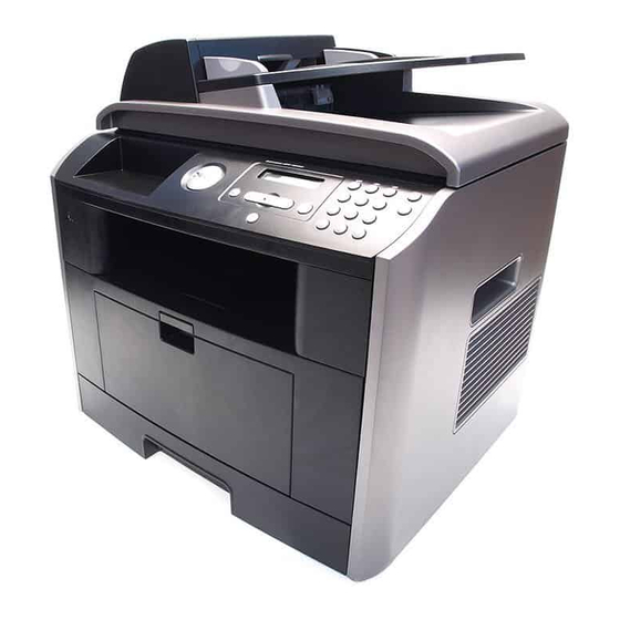
This document is the product specification for Dell 1815dn . Dell 1815dn is a Multi-Function Peripheral (MFP) integrating a plain fax, a B/W laser printer , a color flatbed scanner, and a B/W copier. Dell 1815dn i s devel- oped for small workgroup and personal of fice customers. The main product concept is ° High Speed and High Quality.°±... - Page 20 System Outline 3) SDRAM : is used as Swath Buffer in Printing, Scan Buffer in Scanning, ECM Buffer in FAX receiving, and System Working Memory Area - size : 64Mbyte(Basic) , 96Mbyte(Duplex) 4MB : System Working Memory Area and Scan Buffer 4MB : FAX Memory Receive Area 16MB : Printing System Working Memory Area - Max Frequency : 166MHz...
- Page 21 System Outline Modem (SFX336) specification. 2-wire half-duplex fax modem modes with send and receive data rates up to 33,600 bps V.17, V.34, V.29, V.27 ter, and V.21 Channel 2 Short train option in V.17 and V.27 ter PSTN session starting V.8 and V.8bis signaling HDLC support at all speeds Flag generation, 0-bit stuffing, ITU CRC-16 or CRC-32 calculation and generation...
- Page 22 System Outline Signal Transition of DAA Solution Line Interface Signal of Tel Line and LSD is Analog Signal. 2) there is A/D, D/A Converter in LSD, so Analog Signal from Tel Line is converted in Digital through A/D Converter in DAA and transfer to SSD by DIB Capacitor Digital Signal from SSD is converted to Analog by D/A Converter in DAA and transfer to Tel Line Transformer transfer Clock from SSD to LSD and Clock Frequency is 4.032MHz.
- Page 23 System Outline 4.1.3 Line Interface Part This is Connection Part between system and PSTN(Public Switched Telephone Network), and primary circuit is usually located. Main functions are Line Interface, Telephone Connection and Line Condition Monitoring. 1 Telephone Line Connection Modular Plug : RJ-11C LIU PBA Modular Type : 623 PCB4-4 Line Code Length : 2500 50mm...
- Page 24 System Outline 4.1.4 Scan Part Pictorial signal input part: output signal of CCD passes through Bypass Cap change to ADC at HT82V26, and defined signal between HT82V26 and CHORUSm processes the Image signal. When AFE accept each pixel, CDS(Correlated Double Sampling ) technique which samples arm-level twice is used on each pixel by using CIP4e signal.
-
Page 25: Printer Section
System Outline 4.1.6 Printer Section Printer is consisted of the Engine parts and F/W , and engine parts is consisted of the mechanical parts comprising Frame, Feeding, Developing, Driving, Transferring, Fusing, Cabinet and H/W comprising the main control board, power board, operation panel, PC Interface. The main controller is consisted of ASIC (CHORUSm) parts, Memory parts, Engine Interface parts and it functions as Bus Control, I/O Handling, drivers &... - Page 26 System Outline ASIC Items Specification Remark Process 0.13um (STDH150) Package - 496 PBGA (total pad number:597ea) *PWR & GND pin : - Function pin: about 367pins 114ea*Dedicated PWR - PWR & GND pin: 130pins ( (130/496) 100 = 26.2 %) &...
-
Page 27: Specification
System Outline Items Specification Remark Fully Hardware Rotator/Scaler/Halftoner support Engine Controller - LSU Interface unit, contained APC function. - Step Motor: 4 Phase - PWM: 8 Channels - ADC: 8 Channels - BLDC clock support. DAC(2 ea) I2C Controller I2C bus(SM bus) Slave Device Support (I2C Version 2.1) RTC Core Voltage: 3V 2 PLL (MAIN / (H)PVC ) Service Manual... - Page 28 System Outline Service Manual 4-10...
- Page 29 System Outline 4.1.7 Copier Section Copy Mode: Black and White Scanner Type; CCD with Flatbed/Platen and ADF Maximum Size of Original: Platen: 216 x 297 mm (max. width = 218 mm, ADF: Legal (216 x 356 mm) max length =400 mm) Optical Resolution: 600 x 600 dpi Copy Quality - H x V:...
-
Page 30: Telephone Section
System Outline 4.1.8 Telephone Section Speed Dial: 400 Locations (46 digits maximum per location) On-hook Dial (manual fax): Last Number Redial: Automatic Redial: Pause: Yes (using Redial key) Ringer Volume: Off, Low, Medium, High Tone/Pulse: Selectable (Tech Mode Only no Telecom certification for Pulse mode) 4.1.9 SMPS &... - Page 31 System Outline Charge Voltage (MHV) Input Voltage : 24 V DC Output Voltage : -1.2KV ~ -1.8KV DC Output Voltage Rising Time : 50 ms Max Output Voltage Falling Time : 50 ms Max Output Control Signal(MHV-PWM) : CPU is HV output when PWM is Low Cleaning Voltage (THV-) The (+) Transfer Voltage is not outputted because the THV PWM is controlled with high.
- Page 32 System Outline SMPS (Switching Mode Power Supply) It is the power source of entire system. It is assembled by an independent module, so it is possible to use for common use. It is mounted at the bottom of the set. It is consisted of the AMPS part, which supplies the DC power for driving the system, and the AC heater control part, which supplies the power to fuser.
- Page 33 System Outline Length of Power Cord : 1830 50mm Power Switch : Use Feature Insulating Resistance : 100 or more (at DC 500V) Withstanding Voltage : Must be no problem within 1 min. (at 1000V -LV model / 1500Vac-HV model,10mA) Leaking Current : under 3.5mA Running Current : under 40A PEAK (AT 25 , COLD START) under 60A PEAK (In other conditions)
-
Page 34: Toner Cartridge
System Outline 4.1.10 Toner Cartridge In the toner cartridge, the OPC unit and the developer unit are in a body . The OPC unit has OPC drum and charging roller , and the developer unit has toner, toner cartridge, supply roller, devel- oping roller, and the blade. -
Page 35: Duty Cycle
System Outline 4.1.15 Feeding Part Feeding Type: Universal Cassette Type Feeding Standard: Center Loading Feeding Qty: Cassette 250 sheets (75g/ , 20lb paper standard) Bypass 50 sheet (Paper, OHP, Envelope etc.) Separating Type: Cassette - Friction Pad Type Bypass - Friction Pad Type Driver Type: Driving by Gearing from Main Motor Pick_up Roller Driver: Solenoid 4.1.16 Duty Cycle... -
Page 36: Disassembly And Reassembly
Precautions 5. Disassembly and Reassembly 5.1 General Precautions on Disassembly When you disassemble and reassemble compo- Releasing Plastic Latches nents, you must use extreme caution. The close proximity of cables to moving parts makes proper Many of the parts are held in place with plastic routing a must. -
Page 37: Front Cover
Precautions 5.2 Front Cover 1. Take out the Cassette. 3. If necessary, remove the Toner Cartridge. Toner Cartridge Cassette 2. Open the Cover. 4. To remove the Front Cover, first pull the part below the both side of the Front Cover with a light pressure to the direction of arrow. -
Page 38: Mp Tray Ass'y
Precautions 5.3 MP Tray Ass'y 1. Open the MP Tray Ass'y 3. Apply light pressure to the both side of the MP Tray Ass'y and pull it in the direction of arrow , as shown below. MP Tray Ass'y MP Tray Ass'y 2. -
Page 39: Rear Cover
Precautions 5.4 Rear Cover 1. Open the DIMM Cover from the Left Side Cover in the 3. Remove the four screws securing the Rear Cover and direction of arrow, as shown below. then Release the Rear Cover from the Set. Rear Cover DIMM Cover 2. - Page 40 Precautions 5. Unlatch the Face Up Cover from the Rear Cover and then release the Face Up Cover, as shown below. Face Up Cover Service Manual...
-
Page 41: Fuser Ass'y
Precautions 5.5 Fuser Ass'y 1. Before you remove the Fuser Ass'y, you should 4. To remove the Halogen Lamp, first release REC remove: Harness from the left side of the Halogen Lamp and - Rear Cover (Refer to 5.4) then release the CON Harness from the right side of the Halogen Lamp, as shown below. - Page 42 Precautions 6. Remove the two screws securing the IInput Guide 8. Remove the three screws securing the Idle Gear and remove it. Bracket and remove it. Idle Gear Bracket Input Guide 9. Remove the one screw securing the Fuser Cover and release the Fuser Cover from the Fuser Frame.
- Page 43 Precautions 10. Release the Fuser Gear and HR Bush and then 11. Remove the Jam Link Lever (L,R) and Jam Holder remove the Heat Roller, as shown below. (L,R) and then remove the Pressure Roller, as shown below. Jam Link Lever Heat Roller HR Bush Jam Holder...
-
Page 44: Side Cover (Left, Right)
Precautions 5.6 Side Cover (Left, Right) 1. Before you remove the Side Cover (Left, Right), you 4. Remove the two screws securing the Left Side Cover , should remove: as shown below. - Rear Cover (Refer to 5.4) 2. Remove the two screws securing the Right Side Cover, as shown below. - Page 45 Precautions 6. To remove the DIMM Cover, first open the DIMM Cover (refer to 5.4.1) and then release the DIMM Cover, as shown below. DIMM Cover Notice : Be careful not to damage the hooks when remove the Side Cover (Left, Right). Service Manual 5-10...
-
Page 46: Scanner Ass'y
Precautions 5.7 Scanner Ass'y 1. Before you remove the Scanner Ass'y, you should 4. Pull up the Scanner Ass'y, as shown below. remove: - Rear Cover (Refer to 5.4) Scanner Ass'y - Side Cover (Left, Right) (Refer to 5.6) 2. Remove the two screws securing the Scanner Ass'y, as shown below. - Page 47 Precautions 6. Lift the ADF Ass'y upward to remove it. 9. Remove the four screws securing the Scan Upper . ADF Ass'y Scanner 10. Release the four hooks securing the Scan Upper to the Scan Lower and remove it, as shown below . 7.
- Page 48 Precautions 12. Pull up the CCD Shaft and take out the CCDM. 15. If necessary, remove the two screws securing the Scan Motor and remove it, as shown below. CCDM CCD Shaft Gear Bracket Ass'y Scan Motor 13. Squeeze the spring to release the tension in the Belt and lift from the pulleys, as shown below.
- Page 49 Precautions 16. Unplug the connector from the Open Sensor Ass'y. 19. Unplug the Harness from the CCD Home Sensor and release the CCD Home Sensor, as shown below. CCD Home Sensor Harness 17. Unlatch the Open Sensor and remove it, as shown below.
- Page 50 Precautions 5.8 ADF Ass'y 1. Before you remove the ADF Ass'y, you should 4. Remove the Open Cover, as shown below. remove: - Rear Cover (Refer to 5.4) - Side Cover (Left, Right) (Refer to 5.6) Open Cover - Scanner Ass'y (Refer to 5.7) 2.
- Page 51 Precautions 6. Remo the two screws securing the ADF Upper and 7. Unplug the one connector and remove four screws remove it, as shown below. securing the ADF Motor Ass'y and then remove the one screw securing the Ground Cable, as shown below.
-
Page 52: Ope Unit
Precautions 5.9 OPE Unit 1. Before you remove the OPE Unit, you should remove: 4. Remove the Keys from the OPE Cover. - Rear Cover (Refer to 5.4) - Side Cover (Left, Right) (Refer to 5.6) - Scanner Ass'y (Refer to 5.7) 2. -
Page 53: Shield Controller Ass'y
Precautions 5.10 Shield Controller Ass'y 1. Before you remove the Shield Controller Ass'y, you 4. Remove the three screws securing the Main PBA to should remove: the Bracket and unplug the Film Cable and then - Rear Cover (Refer to 5.4) remove the Main PBA. - Page 54 Precautions 6. Remove the three screws securing the Modem PBA 7. Remove the two screws securing the Speaker to the to the Bracket and unplug the Film Cable and then Bracket and unplug the connector from the Modem remove the Modem PBA. PBA and then remove the Speaker.
-
Page 55: Drive Ass'y
Precautions 5.11 Drive Ass'y 1. Before you remove the Drive Ass'y, you should 3. If necessary, remove the four screws securing the remove: BVDC Motor Ass'y and remove it. - Rear Cover (Refer to 5.4) - Side Cover Left (Refer to 5.6.4) - Shield Controller Ass'y (Refer to 5.10) Gear Bracket Ass’y 2. -
Page 56: Duplex Drive Ass'y
Precautions 5.12 Duplex Drive Ass'y 1. Before you remove the Duplex Drive Ass'y, you should 3. If necessary, remove the two screws securing the remove: Duplex Motor and remove it. - Rear Cover (Refer to 5.4) - Side Cover Right (Refer to 5.6.3) 2. -
Page 57: Shield Smps Ass'y
Precautions 5.13 Shield SMPS Ass'y 1. Before you remove the Shield SMPS Ass'y, you 4. Unplug the connector (AC Inlet) and remove the four should remove: screws securing SMPS and remove it. - Rear Cover (Refer to 5.4) - Side Cover Right (Refer to 5.6.3) Shield SMPS - Duplex Drive Ass'y (Refer to 5.12) (With AC Inlet) -
Page 58: Connection Pcb
Precautions 5.14 Connection PCB 1. Before you remove the Connection PCB, you should 4. The connectors are located, as shown below. remove: FAN Duplex Exit Motor - Rear Cover (Refer to 5.4) - Side Cover Right (Refer to 5.6.3) 2. Unplug the all connectors. Duplex Fan Main Motor... -
Page 59: Fuser Drive Ass'y
Precautions 5.15 Fuser Drive Ass'y 1. Before you remove the Fuser Drive Ass'y, you should 4. If necnsary, remove the two screws securing the Step remove: Motor and remove it. - Rear Cover (Refer to 5.4) - Side Cover Right (Refer to 5.6.3) Fuser Exit Bracket Ass'y 2. - Page 60 Precautions 5.16 Fan 1. Before you remove the Fan, you should remove: 3. Remove the two screws securing the Fans and then - Rear Cover (Refer to 5.4) pull the Fans (Main, Duplex). - Side Cover Right (Refer to 5.6.3) 2.
-
Page 61: Pick Up Roller Ass'y
Precautions 5.17 Pick Up Roller Ass'y 1. Take out the Cassette. 3. To remove the Shaft, first release the locker and slide the Shaft from left to right, then lift the notch attached to the Cam so that it's released from the Shaft. Then release the Bush from the Shaft and remove the Shaft from the Duplex Guide Housing, as shown below. -
Page 62: Duplex Guide Housing (With Feed Roller)
Precautions 5.18 Duplex Guide Housing (With Feed Roller) 1. Before you remove the Duplex Guide Housing, you 4. Pull the Feed Roller from the Bushing. should remove: - Pick Up Roller Ass'y (Refer to 5.17) 2. Remove the two screws securing the Duplex Guide Housing. -
Page 63: Hvps Housing
Precautions 5.19 HVPS Housing 1. Before you remove the HVPS Housing, you should 4. If necessary, remove the three screws securing the remove: HVPS and remove it. - Duplex Drive Ass’y (Refer to 5.12) - Pick Up Roller Ass'y (Refer to 5.17) - Duplex Guide Housing (Refer to 5.18) - Unplug the two Connectors (HVPS) (p5-22) 2. -
Page 64: Middle Cover Ass'y
Precautions 5.20 Middle Cover Ass'y 1. Before you remove the Middle Cover Ass'y, you 3. If necessary, remove the two screws securing the should remove: USB Host PBA and remove it. - Rear Cover (Refer to 5.4) Harness - Side Cover (Left, Right) (Refer to 5.6) - Scanner Ass'y (Refer to 5.7) - Shield Controller Ass'y (Refer to 5.10) USB Host PBA... -
Page 65: Mpf Housing
Precautions 5.22 MPF Housing 1. Before you remove the MPF Housing, you should 3. To remove the MP Pick Up Ass'y, first lift the notch remove: attached to the left side Stopper so that it's slide the - Cover Mid Front (Refer to 5.21) right to left from the Shaft, then left side Idle slid the right to left from the Shaft and take out the MP Pick 2. -
Page 66: Feed Roller Parts
Precautions 5.23 Feed Roller Parts 1. Before you remove the Feed Roller Parts, you should 4. Release the E-Ring securing the Feed2 Gear and remove: remove it. - Pick Up Roller Ass'y (Refer to 5.17) - Duplex Guide Housing (Refer to 5.18) - Middle Cover Ass'y (Refer to 5.20) - MPF Housing (Refer to 5.22) 2. - Page 67 Precautions 6. If necessary, release the three E-Rings securing the 8. Pull up the Feed1 Roller from the Bushing, as shown Gears (T2 Idle, Retard, Idle) and then remove the below. Gears from the Feed Bracket, as shown below. Idle Gear Feed1 Roller Bracket E-Ring...
-
Page 68: Pick Up Gear Ass'y & Solenoids
Precautions 5.24 Pick Up Gear Ass'y & Solenoids 1. Before you remove the Pick Up Gear Ass'y & 3. Remove the two screws securing the Manual Solenoids, you should remove: Solenoid and Feed Solenoid and then remove the - Duplex Guide Housing (Refer to 5.18) Solenoids, as shown below. - Page 69 Precautions 5.26 LSU 1. Before you remove the LSU, you should remove: 2. Remove the four screws securing the LSU and - Middle Cover Ass'y (Refer to 5.20) remove it. 5.27 Terminal PBA 1. Before you remove the CRUM2 PBA, you should 2.
-
Page 70: Transfer Roller Parts
Precautions 5.28 Transfer Roller Parts 1. To remove the Transfer Roller, first push the TR Holder and then take out the Transfer Roller, as shown below. Transfer Roller TR Holder Notice : Do not grab the rubber part of the Transfer Roller, it may cause a malfunction due to a foreigen object. -
Page 71: Alignment And Adjustments
Alignment & Adjustments 6. Alignment and Adjustments This chapter describes the main functions for service, such as the product maintenance method, the test output related to maintenance and repair , DCU using method, Jam removing method, and so on. It includes the contents of manual. 6.1 Paper path Scanner Part Roller-Pickup... -
Page 72: Clearing Paper Jams
Alignment & Adjustments 6.2 Clearing Paper Jams Occasionally, paper can be jammed during a print job. Some of the causes include: • The tray is loaded improperly or overfilled. • The tray has been pulled out during a print job. •... -
Page 73: Clearing Document Jams
Alignment & Adjustments 6.2.1 Clearing Document Jams When a document jams while it passes through the ADF, Document Jam appears on the display. NOTE: To prevent document jams, use the document glass for thick, thin or mixed documents. 1. Remove the remaining documents from the ADF. If the document is jammed in the paper feed area: a. - Page 74 Alignment & Adjustments 2. If you cannot see the paper or the paper does not If the document is jammed in the paper exit area: move when you pulled, open the document cover. a. Open the document cover and turn the release knob to remove the misfed documents from the document 3.
-
Page 75: Paper Feed Jam (Tray 1)
Alignment & Adjustments 6.2.2 Clearing Jams in the Paper Paths When a paper jam occurs, Paper Jam appears on the display . Refer to the table below to locate and clear the paper jam. Operator Panel Message Location of Jam Go to Paper Jam 0 Paper Feed Jam (tray 1) -
Page 76: Paper Feed Jam (Optional Tray 2)
Alignment & Adjustments 6.2.4 Paper Feed Jam (optional tray 2) 1. Pull the optional tray 2 open. 3. Pull the tray 1 half. 2. Remove the jammed paper from the printer. 4. Pull the paper straight up and out. If you cannot see the paper in this area or the paper does not move when pulled, go to the next step. -
Page 77: Fuser Area Jam
Alignment & Adjustments 6.2.6 Fuser Area Jam 2. Remove the paper by gently pulling it straight out. NOTICE: The fuser area is hot. Take care when removing paper from the printer. 1. Open the front cover and lightly pull the toner cartridge straight out. - Page 78 Alignment & Adjustments 5. Release the blue strap, the rear cover stopper , and 8. Pull the jammed paper out. fully open the rear cover, as shown. If the jammed paper does not move when you pull, push the two blue pressure levers up to loosen the paper, and then remove it.
-
Page 79: Duplex Jam
Alignment & Adjustments 6.2.8 Duplex Jam 0 1. Pull the duplex unit out of the printer . If the paper does not come out with the duplex unit, remove the paper from the bottom of the printer . 2. Remove the jammed paper from the duplex unit. 3. - Page 80 Alignment & Adjustments 6.2.9 Duplex Jam 1 1. Open the rear cover. 3. Pull the jammed paper out. 2. Unfold the duplex guide fully. 4. Return the duplex guide and close the rear cover . Printing automatically resumes. Service Manual 6-10...
-
Page 81: Maintenance
Alignment & Adjustments 6.3 User Mode(Dell Laser MFP1815dn) The table in the bellow explains the possible setting functions by user . The details about the ways to use are explained in the user manual. In the service manual, the items are about the possible set-up by user . -
Page 82: Tech Mode
Alignment & Adjustments 6.4 Tech Mode 6.4.1 How to Enter Tech Mode In service (tech) mode, the technician can check the machine and perform various test to isolate the cause of a malfunction. While in Tech mode, the machine still performs all normal operations. To enter the Tech mode To enter the Tech mode, press in sequence, and the LCD... -
Page 83: Modem Speed
Alignment & Adjustments 6.4.3 Data Setup SEND LEVEL You can set the level of the transmission signal. Typically, the Tx level should be under -12 dBm. Caution : The Send Fax Level is set at the best condition in the shipment from factory. Never change settings arbitrarily. -
Page 84: Flash Upgrade
Alignment & Adjustments FLASH UPGRADE The Firmware Upgrade function and has two methods, Local and Remote. (1) Local Machine • RCP(Remote Control Panel) mode This method is for Parallel Port.or USB Port Connect to PC and activate RCP(Remote Control Panel) to upgrade the Firmware. -
Page 85: Dram Test
Alignment & Adjustments 6.4.4 Machine Test SWITCH TEST Use this feature to test all keys on the operation control panel. The result is displayed on the LCD window each time you press a key. MODEM TEST Use this feature to hear various transmission signals to the telephone line from the modem and to check the modem. -
Page 86: Protocol List
Alignment & Adjustments 6.4.5 Report PROTOCOL LIST This list shows the sequence of the CCITT group 3 T.30 protocol during the most recent sending or receiving operation. Use this list to check for send and receive errors. If a communication error occurs while the machine is in TECH mode, the protocol list will print automatically. -
Page 87: Engine Test Mode
Alignment & Adjustments 6.5 Engine Test Mode The Engine Tests Mode supplies useful functions to check the condition of the engine. It tests the condition of each device and displays the result of the test on the LCD. It is classified into 5 functions (0~4), and are shown below . Outline - In order to enter “Engine Test ”... - Page 88 Alignment & Adjustments 6.5.3 Detail Description(Engine Test Mode) Function Name Description Display 01.Motor Test The main motor keeps running after the execution key is Main Motor On(Off) chosen and stops when the stop key is chosen. 02.Pick Up Test automatically Tray 1,2 Solenoid On/Off stops, when the execution is chosen.
- Page 89 Alignment & Adjustments 6.6 Identify Sale Date This function confirms the date that consumer bought product and used the product for the first time. When the consumer first operate the machine, it will start a scan and page count. The time the machine was first used is remembered. These settings are are remembered after memory delete (Clear All Memory).
-
Page 90: Consumables And Replacement Parts
Alignment & Adjustments 6.7 Consumables and Replacement Parts The cycle period outlined below is a general guideline for maintenance. The example list is for an average usage of 50 transmitted and received documents per day. Environmental conditions and actual use will may vary. The cycle period given below is for reference only. -
Page 91: Abnormal Image Printing And Defective Roller
Alignment & Adjustments 6.8 Abnormal Image Printing and Defective Roller If abnormal image prints periodically, check the parts shown below. Transfer Roller OPC Drum Heat Roller Charge Roller Pressure Roller Supply Roller Developing Roller Roller Abnormal image period Kind of abnormal image OPC Drum 75.5mm White spot, Block spot... -
Page 92: Error Messages
Start. You need to press the button ach page to be printed. Invalid Cartridge The toner cartridge you have installed Install a Dell-genuine toner cartridge, is not for your printer. designed for your printer. COMM. Error Retry The printer has a communication Ask the sender to try again. - Page 93 Alignment & Adjustments Display Meaning Suggested solutions Memory Full The memory is full. Delete unnecessary documents, Cancel or Start retransmit after more memory becomes available. Memory Full The memory is full. Split the transmission into more than Divide the Job one operation.
-
Page 94: Troubleshooting
Troubleshooting 7. Troubleshooting 7.1 Paper Feeding Problems 7.1.1 Wrong Print Position Printing begins when the paper is in the wrong position. • Description Check and Cause Solution A defective feed sensor actuator can cause incorrect tim - Replace the defective actuator ing. - Page 95 Troubleshooting 7.1.3 JAM 1 1. Recording paper is jammed in front of or inside the fuser . 2. Recording paper is stuck in the discharge roller and in the fuser just after passing through the • Description Actuator-Feed. Check and Cause Solution L S U 1.
-
Page 96: Multi-Feeding
Troubleshooting 7.1.5 Multi-Feeding Multiple sheets of paper are fed at once. • Description Check and Cause Solution 1. Solenoid malfunction(the solenoid does not work 1. Replace the solenoid if necessary. properly): Perform Engine Test Mode : Diagnostic Mode. 2. Friction-Pad is contaminated with foreign matter.(oil..) 2. - Page 97 Troubleshooting 7.1.7 Paper rolled in the OPC Paper is rolled up in the OPC. • Description Check and Cause Solution 1. Paper is too thin. 1. Recommend to use normal paper thickness. 2. The face of paper is curled. 2. How to remove the rolled paper in the OPC. •...
-
Page 98: Defective Lcd Operation
Troubleshooting 7.2. Printing Problems (malfunction) 7.2.1 Defective Operation (LCD WINDOW ) Display Strange characters are displayed on the OPE Panel and buttons are not operated. • Description Check and Cause Solution 1. Clear the memory. 1. Try again after clearing the memory. 2. -
Page 99: Paper Empty Without Indication
Troubleshooting 7.2.3 Not functioning of the fuser gear due to melting away The Motor breaks away from its place due to gear melting away . • Description Check and Cause Solution 1. Check the Heat Lamp. 1. Replace the Fuser. 2. -
Page 100: Door Open
Troubleshooting 7.2.6 Door Open The ERROR lamp is on even when the print Door is closed. • Description Check and Cause Solution 1. The hook lever in the Front Cover may be defective. 1. Replace the hook lever, if defective. 2. -
Page 101: Defective Motor Operation
Troubleshooting 7.2.8 Defective Motor operation Main Motor is not driving when printing, and paper does not feed into the printer , resulting 'Jam 0'. • Description Check and Cause Solution 1. Motor harness or sub PCB may be defective. 1. Check the Motor harness, replace it, if defective. 2. -
Page 102: Vertical Line Getting Curved
Troubleshooting 7.2.10 Vertical Line Getting Curved When printing, vertical line gets curved. • Description Check and Cause Solution 1. If the supply of +24v is unstable in the Main Control board 1. Replace LSU. linking with LSU, check drive by Engine Test Mode : Diagnostic Code 1 LSU Motor on. -
Page 103: Printing Quality Problems
Troubleshooting 7.3 Printing Quality Problems 7.3.1 Vertical Black Line and Band 1. Straight thin black vertical line occurs in the printing. • Description 2. Dark black vertical band occur in the printing. Check and Cause Solution Digital Printer 1. Damaged develop roller in the Developer. 1. -
Page 104: Horizontal Black Band
Troubleshooting 7.3.3 Horizontal Black Band 1. Dark or blurry horizontal stripes occur in the printing periodically . • Description (They may not occur periodically.) Check and Cause Solution Digital Printer 1. Bad contacts of the voltage terminals to 1. Clean each voltage terminal of the Charge, Digital Printer developer. -
Page 105: Light Image
Troubleshooting 7.3.5 Light Image The printed image is light, with no ghost. • Description Check and Cause Solution Digital Printer 1. Develop roller is stained when the toner 1. Check if the Toner Save Mode is off. Digital Printer of developer cartridge is almost con- sumed. -
Page 106: Uneven Density
Troubleshooting 7.3.7 Uneven Density Print density is uneven between left and right. • Description Check and Cause Solution 1. The pressure force on the left and right 1. Replace both the left and right Spring springs of the transfer roller is not even, Holder. - Page 107 Troubleshooting 7.3.9 Ghost (1) Ghost occurs at 75.5 mm intervals of the OPC drum in the whole printing. • Description Check and Cause Solution Digital Printer 1. Bad contacts caused by contamination 1. Clean the contaminated terminals. Digital Printer from toner particles between high voltage Digital Printer terminal in the main body and the elec Digital Printer...
-
Page 108: Stains On The Front Of The Page
Troubleshooting 7.3.11 Ghost (3) White ghost occurs in the black image printing at 35.2 mm intervals. • Description Check and Cause Solution Digital Printer Digital Printer 1. The life of the developer may be expired. 1. Problem in the toner cartridge, replace the toner cartridge and try to print out. - Page 109 Troubleshooting 7.3.14 Stains on back of the page The back of the page is stained at 47.1 mm intervals. • Description Check and Cause Solution Digital 1. Transfer roller is contaminated. 1. Perform the OPC Cleaning Mode Print 2 or Digital Pri 3 times.
-
Page 110: Fax & Phone Problems
Troubleshooting 7.4 Fax & Phone Problems 7.4.1 No Dial Tone While on-hook button is pressed, there is no dial tone. • Description Check and Cause Solution 1. Check if the telephone line cord is connected to 1. If the telephone cord is normal but there is no dial tone, TEL LINE correctly. - Page 111 Troubleshooting 7.4.3 Defective FAX FORWARD/RECEIVE The FAX FORWARD/RECEIVE is not functioning. • Description Check and Cause Solution 1. Check if you can catch a dial tone by pressing 1. If the MODEM testing is normal and there is no dial OHD.
- Page 112 Troubleshooting 7.4.5 Defective FAX RECEIVE (1) FORWARD is functioning, but RECEIVE is not functioning or the received data are broken. • Description Check and Cause Solution 1.Check if there is NOISE when pressing on-hook 1.If it makes NOISE while on-hooking, replace or repair dial.
- Page 113 Troubleshooting 7.4.8 Defective FAX RECEIVE (4) The received data is reduced by more than 50% in the printing. • Description Check and Cause Solution Check the FAX status of the forwarding side. After checking the data of the forwarding side, correct the FAX of the forwarding side.
-
Page 114: Copy Problems
Troubleshooting 7.5 Copy Problems 7.5.1 White Copy Blank page is printed out when copy. • Description Check and Cause Solution 1. Check the Scan-Cover open. 1. Room light ca transit a thin original. 2. Check shading profile. 2. Remake shading profile in the tech mode. 3. -
Page 115: Abnormal Noise
Troubleshooting 7.5.3 Abnormal noise There is noise when copy. • Description Check and Cause Solution 1. Check the Scanner Motor and any mechanical 1. Check the right position of the Scanner Motor , and disturbance. check the any mechanical disturbance in the CCD carriage part. -
Page 116: Scanning Problems
Troubleshooting 7.6 Scanning Problems 7.6.1 Defective PC Scan The PC Scan is not functioning at all. • Description Check and Cause Solution 1. Check the Cable (USB or Parallel) 1. If the PC and the cable are not connected properly , reconnect it. -
Page 117: Toner Cartridge Service
Troubleshooting 7.7 Toner Cartridge Service It is not guaranteed for the default caused by using other toner cartridge other than the cartridge supplied by the or caused by non-licensed refill production. 7.7.1 Precautions on Safe-keeping of Toner Cartridge Excessive exposure to direct light more than a few minutes may cause damage to the cartridge. 7.7.2 Service for the Life of Toner Cartridge If the printed image is light due to the life of the toner , you can temporarily improve the print quality by redistributing the toner(Shake the toner cartridge), however, you should replace the toner cartridge to solve the problem thoroughly . -
Page 118: Signs And Measures At Poor Toner Cartridge
Troubleshooting 7.7.4 Signs and Measures at Poor toner cartridge Fault Signs Cause & Check Solution • The printed image 1. If the image is light or unclean 1. All of 1, 2, 3 above- Light image and is light or unclean and untidy printed image - (1)The weight of the developer partially blank... - Page 119 Troubleshooting Fault Signs Cause & Check Solution 1. If light or dark periodical black • Light or dark black 1. In case of 1 above - White Black spot dots occur, this is because the dots on the image Run OPC Cleaning Mode Print developer rollers are contami - occur periodically.
- Page 120 Troubleshooting Fault Signs Cause & Check Solution • The printed image 1. The printed image is too light 1. All of 1, 2, 3 above Ghost & Image is too light or dark, or dark, or partially contami- (1)Remove toner and foreign sub- Contamination or partially contami- nated black.
-
Page 121: General Problems
Troubleshooting 7.8 Network Problems Troubleshooting 7.8.1 General Problems Problem Solution System does not function with some wrong Possibly the parameters in PortThru are corrupted.Restart the system values entered y mistake while configuring. and set to factory defaults on the printer front panel or on your computer using SyncThru. -
Page 122: Macintosh Problems
Troubleshooting 7.8.2 Macintosh Problems Problem Solution The printer name is not displayed in the 1.Make sure the printer is connected to network correctly. Chooser. 2.Make sure the printer is configured in SyncThru using the new name. 3.After turning on the printer,wait 3 minutes,then check it again. 4.Make sure that your Macintosh is connected to the network through Ethernet. - Page 123 Troubleshooting Problem Solution SyncThru is unable to automatically detect 1.Check LAN cable is connected to the printers. printers. •Check LAN cable is connected to the printers yourself. •Make sure that there are the connected printers shown in network neighborhood.If not, check the communication status of the printers. •If IP address is assigned to the computers, try ping command.
-
Page 124: Exploded Views And Parts List
Exploded View & Parts List 8. Exploded Views and Parts List 8.1. Main Exploded Views ....................page(8-2) 8.2. Cover Ass'y ......................... page(8-3) 8.3. Middle Cover Ass'y ...................... page(8-4) 8.4. Front Cover Ass'y ......................page(8-5) 8.5. Rear Cover Ass'y ......................page(8-6) 8.6. - Page 125 23-1...
- Page 127 Exploded View & Parts List 8.3 Middle Cover Ass'y Service Manual...
- Page 130 Transfer Roller 36-1 52-1 36-2 36-3 36-4 10-3 10-2 10-1...
- Page 131 Exploded View & Parts List 8.7 Fuser Drive Ass'y Service Manual...
- Page 133 17-1 17-2 17-3...
- Page 134 2-10 2-17 1-21 2-18 2-20 2-11 2-15 1-20 2-16 1-13 1-12 1-19 2-11 2-13 1-16 1-17 2-14 2-12 1-11 2-19 1-15 1-14 1-10 4-19 1-18 4-18 4-17 4-11 4-10 4-12 4-8B 4-15 4-16B 4-8A 4-16A 4-15 4-14 4-13 3-2-4 3-2-3 3-2-5 3-2-1 3-2-2...
- Page 135 Exploded View & Parts List 8.11 Cover Platen Ass'y Service Manual 8-12...
- Page 136 Exploded View & Parts List 8.12 OPE Unit Service Manual 8-13...
- Page 137 Exploded View & Parts List 8.13 Scanner Ass'y 1-1-2 1-1-3 1-1-6 1-1-1 1-1-8 1-1-7 2-2-5 2-2-6 2-2-4 2-2-3 2-2-2 2-2-1 2-2-7 2-10 2-12 2-11 2-13 2-13 2-15 2-14 2-17 2-19 2-18 Service Manual 8-14...
-
Page 141: Front Cover Ass'y
Parts List(Model: Dell 1815dn ) 8.1 Main Exploded Views FRU Item Drawer# SEC Parts Code Description and Specification QT'y Remark (O/X) 8.1-0 D e l l 1 8 1 5 d n 8.1-1 JC96-03792A ELA HOU-FRAME 110V 110V 8.1-1 JC96-03791A... -
Page 142: Frame Assembly
FRU Item Drawer# SEC Parts Code Description and Specification QT'y Remark (O/X) 8.5-0 JC97-02422A MEA-COVER REAR 8.5-1 JC63-00951A COVER-M_REAR 8.5-2 JC61-00961A MAGNET-CATCH DELL 8.5-3 JC63-01028A SHEET-PORT 8.5-4 JC63-00936B COVER-M_FACE UP 8.5-5 JC61-00962A PLATE-MAGNET CATCH 8.5-6 JC63-00937B COVER-M-STACKER REAR 8.5-7 JC61-01653A STOPPER-M-STRAP 8.5-8... -
Page 143: Main Drive Ass'y
FRU Item Drawer# SEC Parts Code Description and Specification QT'y Remark (O/X) 8.6-21 JC33-00010A SOLENOID-HB (MANUAL) 8.6-22 JC33-00014A SOLENOID-FEED ROCKY2 8.6-23 JC63-00917A GROUND-P-DRIVE 8.6-24 JC63-00923A GROUND-P-PUSH BUSHING 8.6-25 JC63-00922A GROUND-P-DRIVE2 8.6-26 6502-001093 CABLE CLAMP 8.6-27 JC61-70932A SPRING ETC-GUIDE DEVE 8.6-28 JC72-00984A PMO-PLATE GUIDE DEVE_L 8.6-29... - Page 144 FRU Item Drawer# SEC Parts Code Description and Specification QT'y Remark (O/X) 8.8-4 JC66-01156A GEAR-OPC RDCN 93/61 8.8-5 JC66-01157A GEAR-OPC DRV 113/33 8.8-6 JC66-01162A GEAR-FEED RDCN 55/18 8.8-7 6031-000023 WASHER-PLAIN 8.8-8 6302-001056 GASKET 8.9 MP Ass'y FRU Item Drawer# SEC Parts Code Description and Specification QT'y Remark (O/X)
- Page 145 HOLDER-M-PAD ADF 8.10-3-2-2 JC61-00387A SPRING ETC-PAD 8.10-3-2-3 JC63-00373A SHEET-ADF HOLDER 8.10-3-2-4 JB73-00052A RMO-ADF RUBBER 8.10-3-2-5 JC66-00738A DAMPER-PAD ADF_R2 8.10-4 JC97-01962A MEA UNIT-PICKUP DELL 8.10-4-1 JC72-00734A PMO-COVER ADF 8.10-4-2 JB66-00103A GEAR-ADF 38 8.10-4-3 JC61-00963A STOPPER-M-PICKUP ADF 8.10-4-4 6044-000159 RING-C 8.10-4-4 JC66-00561A SHAFT-ADF PICKUP 8.10-4-5...
-
Page 146: Cassette Ass'y
QT'y Remark (O/X) 8.13-0 JC96-03778A ELA HOU-SCAN 8.13-1 JC97-02445A MEA UNIT-SCAN UPPER 8.13-1-1 JC97-01941A MEA UNIT-SCAN DUMMY 8.13-1-1-1 JC63-00456A COVER-M-SCAN DUMMY DELL 8.13-1-1-2 JC74-00021A MCT-GLASS ADF 8.13-1-1-3 0203-001744 TAPE-DOUBLE FACE 8.13-1-1-6 JC02-00013A TAPE ETC-DOUBLE TAPE SMALL 8.13-1-1-7 JB68-00644A LABEL(P)-SHADING 8.13-1-1-8... -
Page 147: Duplex Unit
FRU Item Drawer# SEC Parts Code Description and Specification QT'y Remark (O/X) 8.14-7 6107-001166 SPRING-CS 8.14-8 JC73-00141A RPR-PAD CASSETTE 8.14-9 JC66-00719A CAM-M-KNOCK UP 8.14-10 JC61-00876G FRAME-M_CASSETTE 8.14-11 JC61-00918L GUIDE-M_EXTENSION_L 8.14-12 JC61-00960A GUIDE-M-EXTEND S_DELL 8.14-13 JC72-00972A PMO-PLATE_LOCKER 8.14-14 JG61-70531A SPRING ETC-LOCKER,PLATE 8.14-15 JC63-00955A COVER-M_SUB CST... - Page 148 FRU Item Drawer# SEC Parts Code Description and Specification QT'y Remark (O/X) 8.16-16 JC66-20901A BELT-TIMMING...
-
Page 149: Block Diagram
Block Diagram 9. Block Diagram Service Manual... -
Page 150: Connection Diagram
Connection Diagram 10. Connection Diagram Service Manual 10-1... - Page 151 Dell 1815dn - recommended spare part list 17 Oct 2006 MFG P/N MFG Part Description Dell Dell Part Description Base Unit SCX-5525DN/DEL 110V Base Printer KG194 Base Printer, 110V, (Advanced Exchange for US), 1815dn SCX-5525DN/DLL 110V Base printer (with Icon Pannel)
- Page 152 JC96-03810A ELA HOU-ADF TH959 ADF Engine Assembly, 1815dn JC96-03774A ELA HOU-OPE KJ544 OP Panel Assembly for America in English, 1815dn JC96-03774B ELA HOU-OPE GJ636 OP Panel Assembly for Europe & Others in symbol, 1815dn JC96-03762A ELA UNIT-DUPLEX DRIVE RF274 Duplex Drive, 1815dn JC97-02652A MEA-TRANSFER ROLLER WJ045...
Need help?
Do you have a question about the 1815 Mono Laser and is the answer not in the manual?
Questions and answers