Table of Contents
Advertisement
Advertisement
Table of Contents

Related Manuals for Vaisala RS92-SGP


Summary of Contents for Vaisala RS92-SGP
- Page 1 USER'S GUIDE Vaisala Radiosonde RS92-SGP M210295EN-H...
- Page 2 The contents are subject to change without prior notice. Please observe that this manual does not create any legally binding obligations for Vaisala towards the customer or end user. All legally binding commitments and agreements are included exclusively in the...
-
Page 3: Table Of Contents
PRODUCT OVERVIEW ........13 Introduction to Vaisala RS92-SGP ....13 CHAPTER 3 OPERATION . - Page 4 Radiosonde Warranty ......48 Vaisala Radiosonde Warranty Statement ... . .48 Storage Conditions .
- Page 5 List of Figures Figure 1 Vaisala Radiosonde RS92-SGP ..... . . 14 Figure 2 Loading Weights onto the Gas Nozzle....16 Figure 3 Attaching the Balloon to the Gas Nozzle .
- Page 6 User's Guide ______________________________________________________________________ 4 ___________________________________________________________________ M210295EN-H...
- Page 7 Table 4 RS92-SGP Battery Sets....... . 28 VAISALA ________________________________________________________________________ 5...
- Page 8 User's Guide ______________________________________________________________________ 6 ___________________________________________________________________ M210295EN-H...
-
Page 9: Chapter 1 General Information
CHAPTER 1 GENERAL INFORMATION This chapter provides general notes for the manual and the product. About This Manual This manual provides information for operating Vaisala Radiosonde RS92-SGP. Contents of This Manual This manual consists of the following chapters: Chapter 1, General Information: This chapter provides general notes for the manual and the product. -
Page 10: Version Information
M210295EN-E Previous version Related Manuals Table 2 Related Manuals Manual Code Manual Name DOC219110 Vaisala Radiosonde RS92 Quick Guide M210507EN AUTOSONDE AS14 User’s Guide M210329EN Ground Check Set GC25 User's Guide M210488EN Vaisala DigiCORA® User's Guide M210547EN Digital Ozonesonde RS92 User's Guide... -
Page 11: Documentation Conventions
Do not use the radiosonde without consultation and cooperation with local and other applicable aviation authorities. CAUTION Do not modify the unit. Improper modification can damage the product or lead to malfunction. CAUTION Do not use the radiosonde for any purpose other than for soundings. VAISALA ________________________________________________________________________ 9... -
Page 12: Recycling
Dispose of batteries and the unit according to statutory regulations. Do not dispose of with regular household refuse. Regulatory Compliances Vaisala Radiosondes RS92-SGP and RS92-D are in conformity with the following EU directive and with national legislation implementing this directive:... -
Page 13: License Agreement
Chapter 1 ________________________________________________________ General Information License Agreement All rights to any software are held by Vaisala or third parties. The customer is allowed to use the software only to the extent that is provided by the applicable supply contract or Software License Agreement. - Page 14 User's Guide ______________________________________________________________________ 12 __________________________________________________________________ M210295EN-H...
-
Page 15: Chapter 2 Product Overview
The RS92-SGP features easy additional sensor capability. The synthesizer-based transmitter is stable and uses a narrow bandwidth. The RS92-SGP is compliant with the European ETSI standard for digital radiosondes operating in the 400 MHz band, EN 302 054. -
Page 16: Figure 1 Vaisala Radiosonde Rs92-Sgp
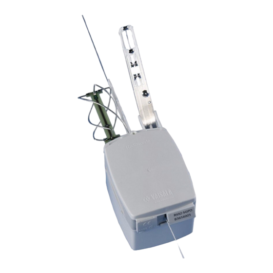
GPS antenna Battery case Additional sensor interface connector Antenna Temperature sensor Humidity sensors Sensor boom GC25 interface Vaisala Radiosonde RS92-SGP can be used with Vaisala Sounding Systems MW41, MW32, MW31 and MW21, and with MW11, MW12, and MW15. 14 __________________________________________________________________ M210295EN-H... -
Page 17: Chapter 3 Operation
Unpack the radiosonde. Prepare the sounding. Connect the battery. Launch the radiosonde. Monitor the sounding with the sounding system. When conducting additional sensor soundings (ozone or radioactivity soundings), follow the procedures and guidelines in the relevant User’s Guides. VAISALA _______________________________________________________________________ 15... -
Page 18: Preparing The Balloon And Optional Sounding
User's Guide ______________________________________________________________________ Preparing the Balloon and Optional Sounding Accessories The balloon and the optional sounding accessories must be prepared before connecting the radiosonde battery and thereby activating the radiosonde. This is necessary because the radiosonde should be launched within 15 minutes of battery connection. WARNING Read the safety instructions in Appendix A before proceeding. -
Page 19: Figure 3 Attaching The Balloon To The Gas Nozzle
Figure 3 Attaching the Balloon to the Gas Nozzle 0705-017 Inflate the balloon following the balloon manufacturer’s inflation instructions. Do not leave the balloon-filling shed while inflating the balloon. Figure 4 Inflating the Balloon 0705-018 VAISALA _______________________________________________________________________ 17... -
Page 20: Figure 5 Balloon Raises The Gas Nozzle
User's Guide ______________________________________________________________________ When the balloon is sufficiently filled, in other words, the balloon just raises the gas nozzle, close the gas valve. Figure 5 Balloon Raises the Gas Nozzle 0705-019 Secure the neck of the balloon tightly with a string before removing the balloon from the gas nozzle. -
Page 21: Figure 7 Removing The Balloon From The Gas Nozzle
Figure 8 Folding the Neck of the Balloon 0705-022 Leave the balloon waiting in the balloon-filling shed while you prepare the radiosonde. Make sure the balloon does not touch anything. Hold the balloon by the neck. VAISALA _______________________________________________________________________ 19... -
Page 22: Optional Sounding Accessories
RS46157 Used with a non-Totex parachute Totex Parachute 5710-5 The recommended parachute is the Totex type 5710-5 (Vaisala code 15046). In the Totex parachute, an elastic ribbon loop hangs the unwinder securely under the spreader. Attach the parachute directly to the balloon with the parachute string. -
Page 23: Radar Reflector
Radar Reflector on page Non-Totex Parachute If you are using a parachute that has no firm objects to prevent the unwinder from twisting, you have to use a hanger board (Vaisala code RS46157). Tie the parachute to the balloon with a string. -
Page 24: Figure 9 Vaisala Radiosonde Sounding Accessories
User's Guide ______________________________________________________________________ Figure 9 Vaisala Radiosonde Sounding Accessories 0908-009 Option 1 = Sounding with a Totex parachute Option 2 = Sounding with no sounding accessories Option 3 = Sounding with a radar reflector Option 4 = Sounding with a non-Totex Parachute Now you can proceed to unpack the radiosonde. -
Page 25: Unpacking The Radiosonde
0912-232 Lift the cardboard flap protecting the sensor boom. Be careful to avoid touching or hitting the sensors on the sensor boom. See Figure 11 on page 24 for information on the contents of the radiosonde package. VAISALA _______________________________________________________________________ 23... -
Page 26: Figure 11 Contents Of The Radiosonde Package
User's Guide ______________________________________________________________________ Figure 11 Contents of the Radiosonde Package 0705-024 Radiosonde Unwinder Battery Remove the radiosonde from the package, free the antenna, and take the unwinder out of the package. Remove the small plastic rubber wire from the unwinder. Figure 12 Unwinder Details 0601-048... -
Page 27: Preparing The Sounding
Chapter 3 ________________________________________________________________ Operation Preparing the Sounding When preparing the sounding, Vaisala Ground Check Set GC25 is connected to the sounding system via cable and operated with the help of the sounding software. NOTE If you are using DigiCORA® Sounding System MW21, software version <... -
Page 28: Figure 14 Radiosonde In The Gc25 With The Communication Cable
User's Guide ______________________________________________________________________ Connect the communication cable to the Ground Check Set interface in the radiosonde. Text "UP" on the connector faces upwards. Figure 14 Radiosonde in the GC25 with the 0705-026 Communication Cable Connected Switch on the PC and start a new sounding with the sounding system software. -
Page 29: Figure 15 Placing The Sensor Boom Into Flight Position
Now proceed to connect the radiosonde battery. NOTE The timer countdown is different for analog (RS92-KL and RS92-K) and digital radiosondes (RS92-SGP, RS92-D): For analog radiosondes, the timer countdown starts on the ground, beginning when the radiosonde is connected to the Ground Check Set. Therefore, you have to add some extra time to the timer to be able to activate and connect the battery and launch the radiosonde. -
Page 30: Connecting The Battery Set
Figure 16 on page 28 Figure 17 on page 29 for examples. The RS92-SGP ordering codes differ depending on the battery type. For instructions on using the Dry-cell Battery Set with switch with AUTOSONDE, see AUTOSONDE AS14 User’s Guide. Table 4... -
Page 31: Connecting The Battery
Chapter 3 ________________________________________________________________ Operation Figure 17 RSB912P Water-activated Battery 0705-030 Connecting the Battery Follow these steps to connect the battery to the radiosonde: Open the foil bag as indicated on the bag. Figure 18 Battery Package 0912-138 VAISALA _______________________________________________________________________ 29... -
Page 32: Figure 19 Battery Connector Shown With Rsb611
User's Guide ______________________________________________________________________ Take out the battery connector (number 1 in Figure 19 on page by gently pulling the wires. Figure 19 Battery Connector Shown with RSB611 0912-140 Connect the battery connector to the radiosonde. Figure 20 Connecting the Battery Connector to the 0705-039 Radiosonde The radiosonde has now been activated. -
Page 33: Connecting The Dry-Cell Battery Set With Switch
Connecting the Dry-cell Battery Set with Switch Follow these steps to connect the Dry-cell Battery Set with switch: Open the foil bag as indicated on the bag. Figure 21 Battery Package for Dry-cell Battery Set with 0706-104 Switch VAISALA _______________________________________________________________________ 31... -
Page 34: Figure 22 Battery Connector
User's Guide ______________________________________________________________________ Take out the battery connector by gently pulling the wires. Figure 22 Battery Connector 0705-031 Take hold of the battery connector (number 1 in the following figures) and fold the wires to the side as shown in Figure 23 on page 32). -
Page 35: Figure 24 Placing Battery Connector Into Connector Holder, Part 2
The wires at the connector end must be located between the connector holder and the batteries, as shown in Figure 24 on page 33, not between the connector holder and the outer wall of the battery case. VAISALA _______________________________________________________________________ 33... -
Page 36: Figure 25 Connecting The Radiosonde To The Battery Case
User's Guide ______________________________________________________________________ Connect the battery connector to the radiosonde, see Figure 25 on page NOTE Make sure the battery connector stays connected into the connector holder all the time. If it becomes loose, battery activation will not work properly. Figure 25 Connecting the Radiosonde to the Battery Case 0705-039... -
Page 37: Checking The Connection
Remove the radiosonde and the battery case from each other, for example using a small coin. See section Removing the Battery Case on page 39 for details. Connect the battery again carefully following the instructions in section Connecting the Dry-cell Battery Set with Switch on page VAISALA _______________________________________________________________________ 35... -
Page 38: Connecting The Water-Activated Battery
User's Guide ______________________________________________________________________ 31, making sure the connector is properly connected to the connector holder in the battery case. Connecting the Water-activated Battery NOTE Wear protective gloves when handling the Water-activated Battery. Follow these steps to connect the Water-activated Battery: Open the foil bag as indicated on the bag. -
Page 39: Figure 29 Battery Immersed In Water
Figure 30 on page Place the battery so that the waxed end points to the small projections on the case. Figure 30 Battery in the Case, Waxed End Circled 0705-041 VAISALA _______________________________________________________________________ 37... -
Page 40: Figure 31 Connecting The Battery Connector To The Radiosonde
User's Guide ______________________________________________________________________ Connect the battery connector to the radiosonde. Figure 31 Connecting the Battery Connector to the 0705-039 Radiosonde The radiosonde has now been activated. Close the battery case. Check from the sounding system software that the telemetry link is working well. -
Page 41: Removing The Battery Case
The unwinder is designed to be tied directly to the balloon. If you cannot attach the unwinder directly to the balloon, for example, when using a radar reflector or a parachute, sounding accessories are VAISALA _______________________________________________________________________ 39... -
Page 42: Attaching The Unwinder To The Balloon
User's Guide ______________________________________________________________________ needed to restrict the movement of the unwinder. For instructions, refer to section Optional Sounding Accessories on page Attaching the Unwinder to the Balloon Follow these steps to attach the unwinder directly to the balloon: Pass the unwinder hook through the loop created by the tied balloon neck. -
Page 43: Totex Parachute
Keep the string length between the radiosonde and the unwinder as short as possible. Checking the Reception Immediately after the release, check the reception of the radiosonde frequency on the receiver. Proceed to monitor the sounding with the sounding system. VAISALA _______________________________________________________________________ 41... -
Page 44: Monitoring The Sounding With The Sounding System
User's Guide ______________________________________________________________________ Monitoring the Sounding with the Sounding System If you have not already done so, enter the surface observation information in the sounding system. Refer to the sounding system documentation for detailed instructions on using the sounding software. 42 __________________________________________________________________ M210295EN-H... -
Page 45: Storage And Transportation
(ref. IEC 60721-3-1 class 1K2): Temperature +5 °C to +40 °C Relative humidity below 85% Vaisala AUTOSONDE storage compartment requirements are: The maximum number of days a radiosonde can be loaded in AUTOSONDE is 24 Relative humidity below 50 % Temperature +15 °C to +35 °C... -
Page 46: Transportation
0 °C, the flight time may be compromised. Transportation Vaisala radiosondes must be transported in their original shipping packages. These packages are designed and built to survive and protect their contents in the environmental conditions described herein with the terminology and standards per standard: IEC 60721-3-2. -
Page 47: Figure 34 Lithium Battery Handling Label
DECLARATION FOR ARTICLES NOT REGULATED AS DANGEROUS GOODS, which should be reused for this purpose after updating the appropriate information. Figure 34 Lithium Battery Handling Label 1002-100 NOTE If the lithium battery is faulty, do not transport it. VAISALA _______________________________________________________________________ 45... - Page 48 User's Guide ______________________________________________________________________ 46 __________________________________________________________________ M210295EN-H...
-
Page 49: Failure Report And Warranty
This chapter presents information about the failure report and radiosonde warranty. Technical Support For technical questions, contact the Vaisala technical support by e-mail at helpdesk@vaisala.com. Follow the instructions below to speed up the repair process and to avoid extra costs to you. -
Page 50: Product Returns
User's Guide ______________________________________________________________________ Product Returns NOTE RMA must always be requested from Vaisala technical support before returning any faulty material. If the product must be returned for service, see www.vaisala.com/ returns. For contact information of Vaisala Service Centers, see www.vaisala.com/services/servicecenters. -
Page 51: Transportation And Handling
Chapter 5 _________________________________________________ Failure Report and Warranty Additional storage requirements for Vaisala AUTOSONDE: the maximum number of days radiosonde can be loaded in AUTOSONDE is 24 relative humidity below 50 % temperature +15 °C to +35 °C Transportation and Handling... -
Page 52: Making Warranty Claims
A failure report shall be provided for each failed radiosonde stating the radiosonde serial number, a description of the failure, and sounding site and date. A template provided by Vaisala can be used for this. A radiosonde found defect prior to launch shall be returned to the nearest Vaisala office. -
Page 53: Safety Instructions For Balloon Operators
Do not touch the balloon with bare hands except when holding it by the neck. Wear soft cotton gloves. Ensure that there are no pointed objects in the shed. Nails, hooks, hinges, padlocks, etc., are dangerous as they might scratch the VAISALA _______________________________________________________________________ 51... - Page 54 User's Guide ______________________________________________________________________ inflated balloon. The balloon film is only 0.05 ... 0.1 mm thick upon launch; the slightest scratch could cause the balloon to burst prematurely. 10. Keep the doors of the shed shut while inflating the balloon on a windy day.
- Page 55 16, 20 DigiCORA® 25, 42 non-Totex parachute ordering codes radar reflector Totex parachute failures covered by warranty ordering codes folding the balloon neck batteries frequency tuning optional sounding accessories ozone sounding VAISALA _______________________________________________________________________ 53...
- Page 56 User's Guide ______________________________________________________________________ securing the balloon neck sensor boom performing sounding preparations sounding monitoring preparations workorder storing the radiosonde radar reflector 21, 41 radioactivity sounding radiosonde activating battery timer setting contents of the package Totex parachute 20, 41 features transportation and handling 43, 49 launching tying the balloon...
- Page 58 *M210295EN*...
Need help?
Do you have a question about the RS92-SGP and is the answer not in the manual?
Questions and answers