Table of Contents
Advertisement
Quick Links
Advertisement
Table of Contents

Related Manuals for Vaisala FS11


Summary of Contents for Vaisala FS11
- Page 1 USER'S GUIDE Visibility Sensor FS11 M211187EN-C...
- Page 2 English versions are applicable, not the translations. The contents of this manual are subject to change without prior notice. This manual does not create any legally binding obligations for Vaisala towards customers or end users. All legally binding obligations and agreements are included exclusively in the applicable supply contract or the General Conditions of Sale and General Conditions of Service of Vaisala.
-
Page 3: Table Of Contents
Cable Selection ..............25 Line Power Cable ............25 Communication Cable ..........27 Installation Procedures ..........28 Foundation Construction ..........28 Mounting when Casting Pad ......... 29 Mounting to Existing Surface ........ 31 Assembling FS11 ............32 VAISALA _________________________________________________________________________ 1... - Page 4 ............. 72 MESSAGE Command ..........73 MESSAGE 1, FS11 ............73 Alarm Status Codes ..........74 MESSAGE 2, FS11 with LM21 ........75 MESSAGE 3, Status Message ........76 MESSAGE 4, Uncompensated Values ....78 MESSAGE 5, Vaisala System Standard ....
- Page 5 ....96 OPEN Command ............96 CLOSE Command ........... 96 Available Commands ........... 97 Parameter Configuration ..........99 Default Settings for FS11 Use ......100 LM21 Standard Initialization ......100 CHAPTER 5 THEORY OF OPERATION ..............101 Hardware Description ........... 103 Measurement Unit FSM102 ........
- Page 6 ............140 Replacing FSC202 ............142 Replacing FSP103 ............146 Replacing Transmitter Module FST102 and Receiver Module FSR102 ......... 149 Replacing/Installing Sensor Cables in FS11 ..155 Replacing Fuses ............. 157 CHAPTER 7 TROUBLESHOOTING ................ 159 Error Messages ............... 160 Errors ................
- Page 7 _________________________________________________________________________________ Electrical Specifications ..........168 Mechanical Specifications ........169 Environmental Specifications ........169 Electromagnetic Compatibility ......... 169 CRC16 Checksum ............170 INDEX ....................... 171 VAISALA _________________________________________________________________________ 5...
- Page 8 ................32 Figure 9 Mounting FS11 Frangible Mast Grounding Cable ..................33 Figure 10 Mounting FS11 Aluminum Mast Using Foundation Kit FS211296 ..........34 Figure 11 Fixing Sensor Arm with Allen Screws ......35 Figure 12 Mounting Rear Panel of Radiation Shield ....
- Page 9 ....152 Figure 56 Transmitter/Receiver Module O-Ring ......152 Figure 57 End Plug with O-Ring ............153 Figure 58 FSP103 and FSC202 Sensor Cable Connections ............... 155 Figure 59 Location of Fuses on FSP103 Board ......157 VAISALA _________________________________________________________________________ 7...
- Page 10 Table 13 LM21 User Level Commands .......... 97 Table 14 LM21 Advanced Level Commands ....... 98 Table 15 Default Settings for LM21 in FS11 Use ...... 100 Table 16 Measurement Unit Event Messages ......112 Table 17 Interface Unit Event Messages ........
-
Page 11: Chapter 1 General Information
First version of this manual. Related Manuals The need for the following manuals, which are for related sensors, computers, displays, and such equipment, depends on the system configuration. (These documents are not included in the standard FS11 delivery.) Table 2 Related Manuals... -
Page 12: Documentation Conventions
Vaisala Oyj and its subsidiaries assume no liability for the consequences of customer's failure to comply with these requirements. - Page 13 CAUTION Because of the danger of introducing additional hazards, do not modify or substitute parts in the instrument. Contact Vaisala or its authorized representative for repairs to ensure that safety features are maintained. VAISALA ________________________________________________________________________ 11...
-
Page 14: Esd Protection
ESD Protection Electrostatic Discharge (ESD) can cause immediate or latent damage to electronic circuits. Vaisala products are adequately protected against ESD for their intended use. However, it is possible to damage the product by delivering electrostatic discharges when touching, removing, or inserting any objects inside the equipment housing. -
Page 15: Recycling
Dispose of batteries and the unit according to statutory regulations. Do not dispose of with regular household refuse. Regulatory Compliances The FS11 (with or without LM21) complies with the following directives and standards: - Low Voltage Directive (2006/95/EC) - EMC-Directive 2004/108/EC) -
Page 16: Trademarks
United States and/or other countries. License Agreement All rights to any software are held by Vaisala or third parties. The customer is allowed to use the software only to the extent that is provided by the applicable supply contract or Software License Agreement. -
Page 17: Chapter 2 Product Overview
The FS11 sensor requires a 115/230 VAC power supply and an RS-232 or an RS-485 cable or a single pair modem line for communication. The instrument sends data and status messages to a remote display unit or a data processing system. -
Page 18: Mechanical Structure
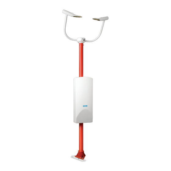
USER'S GUIDE ____________________________________________________________________ Mechanical Structure 1005-009 Figure 1 FS11 System The following numbers refer to Figure 1 above: 1 = Measurement Unit FSM102 2 = Interface Unit FSI102 3 = Pole mast 4 = Background Luminance Sensor LM21 (optional) 5 = FS11OBS Obstruction Light (optional) -
Page 19: Equipment Nomenclature
Chapter 2 ___________________________________________________________ Product Overview The FS11 system is constructed of three main parts (see numbers 1–3 in Figure 1 on page 16): Measurement unit FSM102 includes the measurement CPU, optical parts, transmitter, receiver, and protective hoods equipped with heaters. -
Page 20: Table 4 Fs11 Options Nomenclature
(leased line) DMX501 Modem For remote communication (discontinued) (leased line) LM21 Background Luminance Includes accessories Sensor LM21 for FS11 FSB101 Battery backup QBR101 battery charger and battery 2 Ah FS11OBS Obstruction Light 12 VDC, 7 W obstruction light DRW232138 Sensor Arm... -
Page 21: Chapter 3 Installation
Chapter 3 ________________________________________________________________ Installation CHAPTER 3 INSTALLATION Organizing Installation Before you begin to install FS11 Visibility Sensor, make a plan of the installation steps. The following is an exemplary plan describing how to organize the installation process. Perform site survey:... -
Page 22: Location And Orientation
- FS11 should be located at a minimum distance of 100 m from any large buildings or other constructions that radiate heat and/or obstruct precipitation droplets. The shade of trees should also be avoided because trees may cause changes in the microclimate. - Page 23 LM21 Background Luminance Sensor on page 57). Power supply and communication lines must be available. - When siting the FS11 sensor, consideration must be given to the available power supply and communication lines, as this influences the amount of work and accessories needed, and hence the actual cost of the installation.
-
Page 24: Unloading And Unpacking
Place the packing materials and covers back in the cases and store them for possible reshipment. Storage Information Store FS11 in its packages in dry conditions, not in the open air. The storage conditions are the following: - Temperature -50 °C to +70 °C... -
Page 25: Equipment Grounding And Lightning Protection
Equipment grounding protects the electrical modules of FS11 against, for example, lightning and prevents radio frequency interference. Equipment grounding for the FS11 sensor is done with a jacketed grounding cable and conductive grounding rod(s). The enclosure of the FSI102 interface unit should be grounded using the grounding clamp located under the cable flange (see Figure 3 on page 24). -
Page 26: Figure 3 Fs11 Equipment Grounding
USER'S GUIDE ____________________________________________________________________ 0201-058 Figure 3 FS11 Equipment Grounding The following numbers refer to Figure 3 above: 1 = Grounding clamp 2 = Grounding cable 3 = Grounding rods WARNING A lightning strike can cause a dangerous voltage surge at remote sites through the communication wire if the remote units are not properly grounded. -
Page 27: Cable Selection
Line Power Cable FS11 is supplied with a 3-m power cable with free wire ends. If a local terminal with the power supply of 115/230 VAC is not available, an extended AC (mains) cable from FS11 to the nearest power source is needed. -
Page 28: Figure 4 Junction Box
AC (mains) voltage 230 VAC are shown in Table 6 on page 27. It applies to copper cable and a 5% voltage drop. For the voltage 115 VAC the maximum distances should be divided by four. The maximum power consumption of FS11 is 300 W. 26 ___________________________________________________________________ M211187EN-C... -
Page 29: Communication Cable
3 × 4.0 mm NOTE Cables with diameters more than 15 mm require a separate junction box, such as Termbox1200, available from Vaisala. Communication Cable The customer must provide cables and conduits. The cables used for the transmission of digital and low-level analogue signals should be of the following kind: All field cables should be armored, suitable for underground use, and led to the equipment through conduits. -
Page 30: Installation Procedures
USER'S GUIDE ____________________________________________________________________ Installation Procedures The installation of the FS11 system contains several separate procedures, which are described in the following sections. Foundation Construction Casting a concrete foundation is recommended. An existing level and a rigid construction can also be used. The recommended minimum dimensions for the foundation are illustrated in Figure 5 below. -
Page 31: Mounting When Casting Pad
Mounting when Casting Pad To mount the FS11 system while casting the pad, proceed as follows: Screw on the three reinforcing plates to the lower end of the foundation screws as in Figure 6 on page 30. -
Page 32: Figure 6 Fs11 Foundation Construction
USER'S GUIDE ____________________________________________________________________ 0201-059 Figure 6 FS11 Foundation Construction The following numbers and letter refer to Figure 6 above: 1 = Drilling template 2 = Foundation screw 3 = Reinforcing plate 4 = Background luminance sensor viewing direction (normally North in the Northern hemisphere and South in the Southern... -
Page 33: Mounting To Existing Surface
Chapter 3 ________________________________________________________________ Installation Mounting to Existing Surface To mount the FS11 system to an existing surface, proceed as follows: Place the template on top of the existing foundation. Drill three ∅20 mm holes with a depth of 100 to 260 mm using the drilling template. -
Page 34: Assembling Fs11
USER'S GUIDE ____________________________________________________________________ Assembling FS11 To assemble the FS11 system, proceed as follows: Mount the base plate and level it with six M16 nuts (see Figure 8 below). NOTE If the frangible mast length is more than 3 meters, do not install the tilting support supplied in the Foundation kit FS211296. -
Page 35: Figure 9 Mounting Fs11 Frangible Mast Grounding
Tilt the frangible mast and attach the grounding cable into the grounding support (see Figure 9 below). Raise the mast. 0201-061 Figure 9 Mounting FS11 Frangible Mast Grounding Cable The following numbers refer to Figure 9 above: 1 = Grounding cable 2 = Screw attachment... -
Page 36: Figure 10 Mounting Fs11 Aluminum Mast Using Foundation Kit Fs211296
Foundation Kit FS211296 to mount the pedestal. 0201-062 Figure 10 Mounting FS11 Aluminum Mast Using Foundation Kit FS211296 The following numbers and letter refer to Figure 10 above: 1 = M16 set screws 3 pcs... -
Page 37: Figure 11 Fixing Sensor Arm With Allen Screws
Chapter 3 ________________________________________________________________ Installation 1002-037 Figure 11 Fixing Sensor Arm with Allen Screws 1001-106 Figure 12 Mounting Rear Panel of Radiation Shield VAISALA ________________________________________________________________________ 35... -
Page 38: Figure 13 Tilting Aluminum And Frangible Pole Masts
USER'S GUIDE ____________________________________________________________________ Attach the FSI102 interface unit to the rear panel of the radiation shield (see Figure 19 on page 40). The upper end of the interface unit is mounted by inserting the hook at the back of the interface unit into the groove in the rear panel. -
Page 39: Figure 14 Connecting Measurement Unit
Location and Orientation on page 20 with two 8-mm bolts (see Figure 14 above). The transmitter and receiver heads can be identified by first locating the surface temperature probe, which is closer to the transmitter. Erect the mast. VAISALA ________________________________________________________________________ 37... -
Page 40: Figure 15 Suspending Enclosure From Rear Panel
USER'S GUIDE ____________________________________________________________________ Lift the enclosure of the FSI102 interface unit away from its place and suspend it from the right-side hole in the rear panel by the hook on the backside of the unit. See Figure 15 below. CAUTION Be careful when lifting and suspending the FSI102 interface unit. -
Page 41: Figure 17 Threading Lm21 Cable
LM21 cable connector to make threading easier). Attach the cable to LM21 and mount the LM21 and bracket to the sensor arm. See the correct location for the cable in Figure 17 below. NOTE When connecting LM21, FS11 must be powered off. 1002-043 Figure 17 Threading LM21 Cable Attach the cable connector to the LM21 and mount the LM21 onto the sensor arm as shown in Figure 18 below. -
Page 42: Figure 19 Mounting Interface Unit Enclosure
If the desired LM21 orientation is not possible to obtain by turning the mounting racket, the FS11 rear panel can be adjusted by loosening the screws holding the clamps and rotating the rear panel of the radiation shield. -
Page 43: Figure 20 Sensor Arm Assembly
59 for the wiring inside enclosure. NOTE The cable shield of the Obstruction Light cable must be properly grounded in the cable gland of the interface unit's enclosure. See Figure 25 on page 48. 1011-003 Figure 20 Sensor Arm Assembly VAISALA ________________________________________________________________________ 41... -
Page 44: Inserting Battery For Optional Fsb101
USER'S GUIDE ____________________________________________________________________ Attach the interface unit back in its original place in the rear panel. NOTE Make sure that the cables are not pressed between the interface unit and the rear panel. Attach and close the radiation shield as shown in Figure 21 below. 1001-129 Figure 21 Mounting Radiation Shield... -
Page 45: Figure 22 Backup Battery Without Cover Plate
Attach the cover plate by tightening the four screws holding it. Turn on the AC power switch and the battery backup switch. Close the interface unit and mount the upper interface unit cover after exchange work is finalized. VAISALA ________________________________________________________________________ 43... -
Page 46: Connecting Cables
USER'S GUIDE ____________________________________________________________________ After approximately 5 years of operation, the battery should be replaced to ensure a safe backup operation in case of an AC power outage. NOTE A valve-regulated battery is used for the battery backup. According to the ISO 14001 standard, the battery must be recycled. -
Page 47: Power Cable
NOTE If the line voltage used differs from 230 V (the initial factory setting), check the voltage setting of the FSP103 AC (mains) power supply (alternatives 115 VAC and 230 VAC). See Figure 24 on page 46. VAISALA ________________________________________________________________________ 45... -
Page 48: Figure 24 Cabling Principle
USER'S GUIDE ____________________________________________________________________ 1303-064 Figure 24 Cabling Principle 46 ___________________________________________________________________ M211187EN-C... -
Page 49: Communication Cable
(diameters less than 5mm). Slide the plastic cylinder to the edge of the cable sheath. Turn the cable shield over the cylinder, see Figure 25 below. Tighten the cable with the cable gland and proceed with the wiring. VAISALA ________________________________________________________________________ 47... -
Page 50: Communication Options
Consider your communication needs before the installation. The method of communication depends on the distance between the computer or the display and the FS11 sensor, and on the number of FS11 sensors. The possibilities are described in Table 7 below. -
Page 51: Serial Transmission With
CPU board FSC202. See Figure 26 on page 50. The flow control lines RTS and CTS are not required but they can be used. The hardware flow control can be enabled in FS11 with command SET DATA_PORT RS-232 HW_FLOW_CNTR. During hardware flow control, the control line RTS indicates 'Ready for Receiving'. -
Page 52: Serial Multipoint Transmission With
Figure 26 RS-232 Communication Option Serial Multipoint Transmission with RS-485 The RS-485 transmission standard allows several FS11 sensors to communicate (half-duplex) with the host computer using a single twisted pair. The RS-485 interface is opto-isolated. For the RS-485 communication method, connect the signal wires to the screw terminal at the CPU board. -
Page 53: Figure 27 Rs-485 Communication Option
RS-485 Communication Option Terminate the RS-485 chain with a 120 Ω resistor. This is especially important with long cables. If the FS11 sensor is at the end of the RS-485 chain, the 120 Ω resistor can be connected across the screw terminal pins. -
Page 54: Modem Dxl421 (Optional)
NOTE The DXL421 modem replaces the DMX501 modem. The DMX501 modem is no longer available but it can still be used with FS11. The replacement of the modem does not cause any changes to the data transmission through modem, except that v.22 bis is no longer supported. - Page 55 - Originate or Answer - 1200 baud or 300 baud - Speed buffer for 9600 baud On/Off - 2-wire or 4-wire The default settings are: - Answer - 300 baud - Speed buffer for 9600 baud Off - 2-wire VAISALA ________________________________________________________________________ 53...
-
Page 56: Figure 30 Installing Dxl421
USER'S GUIDE ____________________________________________________________________ 1303-066 Figure 30 Installing DXL421 The following number refers to Figure 30 above: 1 = DXL421 Modem module 2 = Wire set for DXL421 3 = Screw terminals 1 and 2 for DXL421 supply voltage 4 = FSC serial data line 54 ___________________________________________________________________ M211187EN-C... -
Page 57: Multipoint Modem Connection
300 bps V.21. In this configuration the data collection computer or the weather station acts a master that polls all the FS11 sensors and the other possible sensors. The master modem must be in the Originate mode. All other modems on the line must be in the Answer mode and the Carrier signal must be disconnected by default. -
Page 58: Maintenance Terminal Connection
The upper connector is reserved for PWD32 unit (only in use in FS11P) and lower for FS11 (see Figure 31 below). The connector is protected with a cap. Replace the protective cap after disconnecting the maintenance cable. -
Page 59: Background Luminance Options
Chapter 3 ________________________________________________________________ Installation Background Luminance Options FS11 can be fitted with one of two Background Luminance Sensor options: LM21 Background Luminance Sensor, for use in Runway Visual Range (RVR) systems Day/Night Photo Switch, for general nighttime meteorological visibility LM21 Background Luminance Sensor The optional LM21 sensor offers the means for measuring ambient light level or background luminance in RVR applications. -
Page 60: Figure 32 Wiring Day/Night Photo Switch
USER'S GUIDE ____________________________________________________________________ A closed contact of the Day/Night Photo Switch corresponds to darkness, that is, nighttime. NOTE The cable shield of the photo switch cable must be properly grounded in the cable gland of the interface unit's enclosure, see Figure 25 on page 1303-067 Figure 32 Wiring Day/Night Photo Switch... -
Page 61: Obstruction Light Option
The activation of the obstruction light option requires the use of the advanced level command . See Table 10 on page 67 for SET +12VOUT ON a list of advanced level commands. 1303-061 Figure 33 Obstruction Light Wiring VAISALA ________________________________________________________________________ 59... -
Page 62: Startup
USER'S GUIDE ____________________________________________________________________ Startup Before closing the cover of the interface unit's enclosure, a short startup procedure is recommended. Connect a terminal to the sensor through a serial line (see section Serial Transmission with RS-232 on page 49 or Maintenance Terminal on page 56). -
Page 63: Initial Settings
Initial Settings FS11 Visibility Sensor is typically interfaced to a host computer or a data logger in an automatic weather observation system. After the physical connection has been made, the details of the communication can be configured into the FS11 software. - Page 64 USER'S GUIDE ____________________________________________________________________ This page intentionally left blank. 62 ___________________________________________________________________ M211187EN-C...
-
Page 65: Chapter 4 Operation
Entering and Exiting Command Mode Before any commands can be given to the FS11 sensor, the maintenance or data line of FS11 has to be assigned to the operator. Otherwise it is assigned to automatic messages or polled communication. The user enters the command mode with command OPEN. -
Page 66: Open Command
If the device type FS is included in the OPEN command, an ID is not needed. This device type can be used when there is only one FS11 sensor on the line. This command is similar to the OPEN * command with the exception that it only opens the FS11 command mode and not the other possible sensors on the line. -
Page 67: Close Command
If no ID is defined the FS11 sensor answers: FS11 LINE CLOSED If an ID is defined, for example, as A, the FS11 sensor answers: FS11-A LINE CLOSED Available Commands With the HELP command the operator can get information about the available commands. - Page 68 SET MESSAGE TYPE FD12MSG2 Selects the FD12 message 2 emulation mode. The data message, message frames, and polling format are the same as they are in Vaisala FD12 Visibility Meter. SET MESSAGE TYPE FD12MSG7 Selects the FD12 message 7 emulation mode. The data message, message frames, and polling format are the same as they are in Vaisala FD12P Weather Sensor.
-
Page 69: Table 10 Fs11 Advanced Level Commands
NAME Displays the device type, device name given by the user, and ID. VERSION Lists the software version. Table 10 FS11 Advanced Level Commands Command Description CALIBRATE WINDOW_CLEAN Sets the clean references for contamination control (and VISIBILITY_SENSOR backscatter control) in FS11. - Page 70 Selects the FD12 message 2 emulation mode for the FD12MSG2 Second Message. The data message, message frames, and polling format are the same as they are in Vaisala FD12 Visibility Meter. SET MESSAGE SECOND TYPE Selects the FD12 message 7 emulation mode for the FD12MSG7 Second Message.
- Page 71 SET BL_SENSOR PHOTO_SWITCH Enables Day/Night photo switch reading. SET BL_SENSOR OFF Disables Background Luminance Sensor data polling and photo switch reading the in FS11 system (default). SET VIS_SENSOR ON Enables Visibility Sensor data polling in the FS11 system (default). SET VIS_SENSOR OFF Disables Visibility Sensor data polling in the FS11 system.
-
Page 72: Command Completion
USER'S GUIDE ____________________________________________________________________ Command Description a preset level. SET DEW _HEATER BL_ SENSOR OFF Disables dew heaters operation and monitoring. Set OFF when operated in environments where dew heaters are not needed (ambient temperature does not drop below 12 °C). SET MESSAGE FRAME ON Message frames included in data message transmission (default). -
Page 73: Terminal Line Number Adjustment
The general command polling format (with A as the unit ID) is !FSA∀&DO COMMAND−#CSUM∃−∗ where = Start of the heading (ASCII 1) = FS11 sensor identifier = First character of the unit identifier, if the ID is not defined it is replaced by a space character = Start of the text (ASCII 2) ∀... -
Page 74: Message Formats
The polling request can ask for the automatic (default) or some other message (with a message number). When used as a part of an RVR system, the FS11 sensor can emulate the messages of Vaisala MITRAS Transmissometer (Single or Double Baseline), FD12 Visibility Meter and FD12P Weather Detector. -
Page 75: Message Command
MESSAGE command is MESSAGE Message_number If the message number is not specified, FS11 displays a default message. The default message is the message that has been selected for automatic or polled mode with command SET MESSAGE TYPE. -
Page 76: Alarm Status Codes
USER'S GUIDE ____________________________________________________________________ The total amount of characters in the message is 43. The transmission times are: 1.5 s at 300 bps (10-bit char), 0.19 s at 2400 bps, 0.05 s at 9600 bps. Alarm Status Codes The alarm status codes are listed in Table 11 below. Table 11 Alarm Status Codes Code... -
Page 77: Message 2, Fs11 With Lm21
Chapter 4 _________________________________________________________________ Operation MESSAGE 2, FS11 with LM21 Message 2 is a message of fixed length where both visibility and background luminance values are shown. The message 2 format is as follows: !FSA∀VIS 02000 AL 0 BL 01000 AL 0#CSUM∃−∗... -
Page 78: Message 3, Status Message
STATUS command. The short status check message, which contains a short, clear language report of the system status can be requested with command STATUS CHECK. Refer to section FS11 Status Messages on page 111. Example of status message: !FSA∀FS11 SYSTEM STATUS: OK... - Page 79 For a list of alarm status code explanations, see Table 11 on page 74. The count of characters in the message is variable and depends on the configuration and status of the FS11 system. The total amount can be up to 1400 characters. The transmission of 1400 characters needs 47 s at 300 bps (10-bit char), 5.8 s at 2400 bps or 1.5 s at 9600 bps.
-
Page 80: Message 4, Uncompensated Values
!FSA∀VIS 02100 VUC 02100 VIS3M 02000 VIS10M 01900 AL 0 BL 01050 BUC 01050 AL 0#CSUM∃−∗ where Start of the heading FS11 sensor identifier First character of the unit identifier, if the ID is not defined it is replaced by a space character Start of the text ∀... -
Page 81: Message 5, Vaisala System Standard
For a list of alarm status code explanations, refer to Table 11 on page 74. FD12 Emulation For compatibility in the system level, the FS11 sensor also supports the message format, frames, and polling format of Vaisala FD12 Visibility meter and Vaisala FD12P Weather Sensor. The FD12/FD12P polling format is accepted only when the FD12/FD12P message emulation is selected. -
Page 82: Fd12 Message 2
USER'S GUIDE ____________________________________________________________________ FD12 Message 2 The FD12 message 2 emulation mode is selected with command SET MESSAGE TYPE FD12MSG2. The message format of the emulated Vaisala FD12 message number 2 is presented below: !FD A∀00 1810 1353 //// // /////# −∗... -
Page 83: Fd12P Message 7
Chapter 4 _________________________________________________________________ Operation FD12P Message 7 The FD12P message 7 emulation mode is selected with command SET MESSAGE TYPE FD12MSG7. The message format of the emulated Vaisala FD12P message number 7 is presented below: A∀00 22848 24807 // // //... -
Page 84: Mitras Emulation
(1 = day, 0 = night). MITRAS Emulation For compatibility in the system level, the FS11 sensor also supports the message number 6 format, frames, and polling format of Vaisala MITRAS Transmissometer. The MITRAS polling format is accepted only when the MITRAS message emulation is selected. - Page 85 1.3 s at 300 bps (10-bit char), 0.17 s at 2400 bps, 0.04 s at 9600 bps. The binary status is in hexadecimal notation. The status bits emulate the MITRAS status as follows. Transmitter status correspondence between MITRAS and FS11: MITRAS FS11 BIT.0=1 MEAS MODE BIT.1=2...
-
Page 86: Mitras Double Baseline
USER'S GUIDE ____________________________________________________________________ MITRAS Double Baseline The MITRAS Double Baseline emulation mode is selected with command SET MESSAGE TYPE MITRAS_DB. The emulated Vaisala MITRAS Transmissometer message is presented below: ∀ID 1 V 4550 B ///// S010101−∗# ---------------------------------- ¦ ¦ ¦... - Page 87 Chapter 4 _________________________________________________________________ Operation Receiver 1 status correspondence between MITRAS and FS11: MITRAS FS11 BIT.0=1 MEAS MODE BIT.1=2 CONT/OTHER Any other FS11 alarm BIT.2=4 OPTICAL SURFACE BIT.3=8 POWER SUPPLY BIT.4=1 HEATING BIT.5=2 CALIBRATION Receiver saturated BIT.6=4 TEST BIT.7=8 CONSISTENCY Receiver 2 status correspondence between MITRAS and FS11:...
-
Page 88: Message Sending Modes
The automatic message number is also the default number for the MESSAGE command and polling. ACK/NAK Confirmation In the automatic mode the FS11 system can be configured to require an acknowledgement for the message reception from the receiver of the message. By default the ACK/NAK confirmation is disabled. The format... - Page 89 MESSAGE ACKNAK ON. After the transmission of the last character of a message the FS11 system expects an ACK/NAK confirmation within 500 ms. If the FS11 receives an ACK character (ASCII 06) within 500 ms, message sending will continue as configured by the SET MESSAGE INTERVAL command.
-
Page 90: Polled Mode
USER'S GUIDE ____________________________________________________________________ Polled Mode In the polled mode the FS11 sensor sends a data message when the host computer transmits a polling command. The automatic message sending mode is disabled by setting the message interval to zero with the... -
Page 91: Second Message
Chapter 4 _________________________________________________________________ Operation When the FD12, FD12P or MITRAS emulation is on (message types FD12MSG2, FD12MSG7, MITRAS, MITRAS_DB are selected), FS11 does not respond to the above polling command but to polling commands sent in FD12, FD12P and MITRAS formats, respectively. -
Page 92: System Configuration
The CALIBRATE command is available only at the advanced level. For calibration instructions, refer to section FS11 Calibration on page 127. The current system parameters can be displayed by using the PARAMETERS command. The output is as follows: >... -
Page 93: Optional External Sensors
BL_SENSOR PHOTO_SWITCH. A positive voltage is interpreted as a night condition and the background luminance value in the FS11 output message is set to 0. Zero voltage or an open circuit is interpreted as a day condition and the luminance value is set to 1. -
Page 94: Simulated Test Messages
USER'S GUIDE ____________________________________________________________________ Simulated Test Messages Visibility Sensor FS11 can be set to a simulation mode, which includes transmitting fixed or user defined visibility and status information. This function is intended for system testing purposes. The normal visibility detection mode takes effect after a reset. The simulation mode can also be stopped with the advanced level command SIMULATE OFF. -
Page 95: Manual Simulation Message
MANUAL_MESSAGE command in the following way: SIMULATE MANUAL_MESSAGE string The FS11 sensor does not make any validity checks to the message body content which means that the message is transmitted as it is written. Special characters can be added to the message by using the following... - Page 96 USER'S GUIDE ____________________________________________________________________ An example of manual simulation message is as follows: The following command SIMULATE MANUAL_MESSAGE this\sis\stestmessage sends the following message ∀ ∃−∗. this is testmessage EE5E In the automatic message sending mode, the frames are not displayed with the MESSAGE command. 94 ___________________________________________________________________ M211187EN-C...
-
Page 97: Operating Lm21 Through Maintenance Port
(closed) to enable use by the host processor FSC202. This enables the operation of the LM21 as a part of FS11. Serial Communication Settings In this FS11 application the default settings of the serial communications port are as follows: - 9600 baud - No parity... -
Page 98: Entering And Exiting Command Mode
USER'S GUIDE ____________________________________________________________________ Entering and Exiting Command Mode The maintenance line of the sensor must be assigned to the operator with command OPEN. OPEN Command If no device identifier (ID) is defined, type OPEN If ID is defined, for example, as A, type OPEN A If ID is defined but forgotten, type OPEN *... -
Page 99: Available Commands
ID. VERSION Lists the software version. SET DATA_PORT BAUD number yes/no Sets data port serial line baud rate to 300...19200. Verification yes/no asked only if the command is given via DATA PORT (default 9600). VAISALA ________________________________________________________________________ 97... -
Page 100: Table 14 Lm21 Advanced Level Commands
USER'S GUIDE ____________________________________________________________________ Command Description SET DATA_PORT PARITY 7E1 yes/no RS-232 and RS-485 serial lines use the following communication parameters: 7 data bits, even parity, 1 stop bit. Verification yes/no asked only if the command is given via DATA PORT (default). SET DATA_PORT PARITY 8N1 yes/no RS-232 and RS-485 serial lines use the following communication parameters: 8 data bits, no parity, 1... -
Page 101: Parameter Configuration
> PARAMETERS LM21 parameter values: identifier: - name: command terminal: lines: timeout: message: type: interval: port: data data port: speed: 9600 data format:8n1 maintenance port: speed: 9600 The system parameter values are saved in the non-volatile EEPROM memory. VAISALA ________________________________________________________________________ 99... -
Page 102: Default Settings For Fs11 Use
USER'S GUIDE ____________________________________________________________________ Default Settings for FS11 Use Table 15 below lists the default settings for LM21 in FS11 use. Table 15 Default Settings for LM21 in FS11 Use Parameter Default Setting Message type Message interval 0 (Off) Message port... -
Page 103: Theory Of Operation
Chapter 5 _________________________________________________________ Theory of Operation CHAPTER 5 THEORY OF OPERATION Visibility Sensor FS11 is a forward scatter measuring instrument. It consists of Measurement Unit (FSM102), Interface Unit (FSI102), frangible mast (FS25010) and interconnecting cables. Measurement Unit FSM102 consists of the Receiver module, the Transmitter module, and the control board. -
Page 104: Figure 35 Fs11 Block Diagram
USER'S GUIDE ____________________________________________________________________ 1006-120 Figure 35 FS11 Block Diagram 102 __________________________________________________________________ M211187EN-C... -
Page 105: Hardware Description
2.2 kHz. A PIN photodiode monitors the transmitted light intensity and automatically adjusts the light level of the LED to the preset value. This compensates for the temperature and aging effects of the light emitting diode. VAISALA _______________________________________________________________________ 103... -
Page 106: Figure 36 Fst102 Transmitter Block Diagram
USER'S GUIDE ____________________________________________________________________ 0009-005 Figure 36 FST102 Transmitter Block Diagram A pulse signal from the FSR102 Receiver synchronizes the infrared LED timing with the lock-in amplifier of the receiver. An additional photodiode measures the light scattered back from the lens, other objects, or contaminants. -
Page 107: Receiver Unit Fsr102
The receiving PIN photodiode senses the transmitted light pulses scattered from the aerosol particles. The signal voltage is filtered and detected by the phase sensitive lock-in amplifier that is synchronized with the transmitter. VAISALA _______________________________________________________________________ 105... -
Page 108: Figure 38 Fsr102 Receiver Block Diagram
USER'S GUIDE ____________________________________________________________________ 0009-006 Figure 38 FSR102 Receiver Block Diagram An ambient light level as high as 30 kcd/m neither influences the detection of the photodiode, nor saturates the preamplifier. The DC level is monitored for detecting eventual saturation caused by the ambient light. -
Page 109: Controller Board Fsc102
Background Luminance Sensor LM21 and optional Obstruction Light Sensor FS11OBS. The external power input and the communication interfaces of the FS11 sensor are located in the interface unit. All external interfaces are equipped with surge protection circuitry. -
Page 110: Communication Controller Board Fsc202
(FS11OBS) or the photo switch. The maximum output current is 0.8 A. The Pt100 and the humidity measurement inputs are not used in the FS11 Visibility Sensor application. If a Vaisala HMP45D probe is connected to the inputs, T and RH are measured and the values are shown in the status message but not used for anything. -
Page 111: Battery Backup
30 minutes (at 25 °C) in case of a power failure. If the unit is operating in a non-freezing environment and the high power hood heaters are not required, the FS11 sensor can also be operated with DC power. The battery charger QBR101 also provides interfaces for solar panels and larger external batteries. -
Page 112: Software Description
USER'S GUIDE ____________________________________________________________________ Software Description The FS11 sensor has a fixed program tuned by the system parameters. The program code includes the signal processing algorithms and the system timing. After a hardware reset or a power-up, the program initializes its working data structures and reads the system parameters from the non-volatile FLASH memory into the data memory. -
Page 113: Calculations
The FS11 sensor generates a warning if some monitored value does not meet the criteria for optimal operation, but the measurement results are still reliable. For example, slightly contaminated windows or aging transmitter LEDs generate warnings. -
Page 114: Event Messages
USER'S GUIDE ____________________________________________________________________ Event Messages This section describes the Event Messages of the different units. Table 16 Measurement Unit Event Messages Event Message Reason MOR1:MOR underrange Measured MOR above upper measurement range limit MOR2:MOR overrange Measured MOR below lower measurement range limit Cal1:calibration procedure Measurement Unit calibration procedure is... -
Page 115: Table 17 Interface Unit Event Messages
Check connected device for short circuit. To bring the +12 V output back into operation, the interface unit needs a reset. CPU2:memory failure Interface unit CPU detected a memory failure. If the failure persists after power-resets of VAISALA _______________________________________________________________________ 113... -
Page 116: Table 18 Background Luminance Detector Sensor Event Messages
Background luminance sensor total Measurement Failure reflection measurement failure The long status message with numerical internal monitoring measurement values is requested with command STATUS as follows: >STATUS FS11 SYSTEM STATUS: OK Measurement unit: OK Receiver: Window cont: 0 backscatter: 114 __________________________________________________________________ M211187EN-C... - Page 117 Window cont: Contamination compensation: ON Backscatter: CPU: 26.2 hood: 24.6 Heater status: hood: OFF, dew: V5iso: where FS11 System status System level status Measurement unit FSM102 status Receiver: Window cont Reduction in window transmittance, in % Backscatter Signal level from total blockage signal, in %...
- Page 118 USER'S GUIDE ____________________________________________________________________ Hood TX Transmitter hood temperature Voltages: +12 V Regulated positive operating voltage for transmitter, receiver, and FSC101 -12 V Regulated negative operating voltage for transmitter and receiver Voltage which +12 V is regulated from Voltage which +5 V is regulated from Heater status: Hood TX TX hood heater automatic control system...
-
Page 119: Alarm Messages
An asterisk (*) in front of the heater status (ON/OFF) indicates that the heater is currently heating. Alarm Messages This section describes the different alarm message types of the FS11 sensor. Table 19 Error Messages... -
Page 120: Optical Contamination And Blocking Monitoring
Optical Contamination and Blocking Monitoring Optical contamination and blocking of both the transmitter and the receiver are continuously monitored. The FS11 sensor monitors contamination and blocking by measuring window contamination and backscattered signals. The CLEAN command is used to set clean reference values for the contamination and blocking signals. -
Page 121: Contamination Compensation
If the contamination compensation is disabled with command SET CONTAMINATION_COMPENSATION VISIBILITY_SENSOR OFF, no contamination compensation is made. However, in this case the window contamination warning is still generated if the total transmission of the windows has decreased. VAISALA _______________________________________________________________________ 119... -
Page 122: Signal Monitoring
The offset error of the receiver unit in FS11 is monitored regularly. CPU disables the transmitter unit and performs the normal scatter measurement procedure without the transmitted light pulses. In case the high offset signal level is too high, a SIGNAL OFFSET DRIFTED alarm message is given and the visibility data is set as missing (/////). -
Page 123: Heaters Operation
FSC202. If the voltage input value (PVin) is above 15 V, the AC (mains) voltage is connected. If the input voltage is below 15 V, the FS11 sensor is working on the battery and a WORKING ON BATTERY indication is generated. If the voltage input value drops below 11 VDC, a BATTERY LOW warning is generated. -
Page 124: Analog Interfaces
USER'S GUIDE ____________________________________________________________________ The +12 VOUT output voltage line is also monitored. The output is protected with a 0.9 A self-resettable fuse. If the fuse has disconnected a line due to, for example, a temporary short-circuit, the software disconnects the entire output and waits for approximately one minute for the fuse to cool and reset itself back to operation, and then connects the +12 VOUT voltage back on-line. -
Page 125: Memory Tests And Program Operation
Memory Tests and Program Operation After a reset, the FS11 sensor clears and initializes its SRAM data memory. The checksum of the FLASH parameter memory is calculated and checked with a test after the reset. -
Page 126: Background Luminance Sensor
USER'S GUIDE ____________________________________________________________________ Background Luminance Sensor The hardware and measurement monitoring of LM21 Background Luminance Sensor is done by the sensor itself. Refer to the LM21 User's Guide (see section Related Manuals on page 9) for the monitored parameters. Error Log All indications, warnings, alarms, and errors resulting from internal monitoring are stored in the error log for maintenance purposes. -
Page 127: Chapter 6 Maintenance
MAINTENANCE Cleaning FSM102 Windows The cleaning of windows and hoods is the only periodic maintenance task required. The FS11 sensor can compensate for a reasonable amount of window contamination, but when a certain limit is exceeded, cleaning is required. The windows and hoods must be cleaned at least every six months or more often, depending on the conditions (for example, if there are roads nearby). - Page 128 USER'S GUIDE ____________________________________________________________________ If the WINDOW CONT values are not close to zero, give command CALIBRATE WINDOW_CLEAN VISIBILITY_SENSOR. This command has no parameters and it is used to set the clean references for the contamination control. The command also sets the reference for the backscatter measurement.
-
Page 129: Fs11 Calibration
Chapter 6 _______________________________________________________________ Maintenance FS11 Calibration The FS11 sensor has been calibrated at the factory. Normally FS11 needs no recalibration as long as the circuit boards are not replaced or there are no warnings or alarms. The circuit boards need no hardware calibration. -
Page 130: Fsm102 Calibration Check Procedure
USER'S GUIDE ____________________________________________________________________ FSM102 Calibration Check Procedure The calibration check procedure is performed as follows: Clean the windows following the instructions in section Cleaning FSM102 Windows on page 125 and check the condition of the calibrator glass plates, cleaning them also, if necessary. In order to block the light path, install the zero plugs on both receiver and transmitter optics (see Figure 40 below). -
Page 131: Fsm102 Calibration Procedure
FSM102 Calibration Procedure The calibration procedure is performed as follows: Follow the steps in section FSM102 Calibration Check Procedure on page 128 (if not yet done). Install the calibrator assembly on the measurement unit (if not yet done). VAISALA _______________________________________________________________________ 129... -
Page 132: Fsm102 Mechanical Alignment Check Procedure
Check the correct calibrator value from the opaque glass plates. The calibrator value is printed on the labels of the glass plates. When command execution has finished, the FS11 responds DONE and calculates a new scaling factor and stores it in the non-volatile FLASH memory. -
Page 133: Fsm102 Guided Calibration Procedure
If the value produced by the check command is more than 85% of the value recorded without the mask plates, the mechanical alignment is correct. If this is not the case, check the FS11 sensor and the calibrator for electronic or mechanical faults. Also consult your local Vaisala representative. - Page 134 The procedure cannot be aborted or suspended. At the end of the Guided Calibration Procedure a summarizing report is generated. Give the CALIBRATE FS11 command. The instrument responses: Step 1/3 Clean Windows and type YES: YES ..||||||||||...
- Page 135 The test has failed when the deviation is greater than ±20%. Move away from the optical path and enter the signal value written on the calibrator assembly to the data terminal. VAISALA _______________________________________________________________________ 133...
-
Page 136: Evaluating Results Of Guided Calibration Procedure For Measurement Unit
USER'S GUIDE ____________________________________________________________________ Confirm the entered signal value by typing YES and Enter or re- enter the signal value after typing NO and Enter. - The Scatter Signal Test starts and the progress is indicated on the screen. - The test step can take up to two minutes. - When the Scatter Signal Test is finalized a test result summary and a passed/ fail indication for the Scatter Signal Test is given. -
Page 137: Table 23 Successful Guided Calibration Procedure
Chapter 6 _______________________________________________________________ Maintenance Table 23 Successful Guided Calibration Procedure 1> CALIBRATE FS11 Step 1/3 Clean Windows and type YES: YES Step 2/3 Zero Value Test and Scatter Signal Test are passed Install Zero Plugs and type YES: YES successfully. -
Page 138: Table 24 Guided Calibration Procedure, Calibration
Table 24 below shows an example of a successful Guided Calibration Procedure with a calibration update for the measurement unit. Table 24 Guided Calibration Procedure, Calibration Update 1> CALIBRATE FS11 Step 1/3 Clean Windows and type YES: YES Step 2/3 Zero Signal Test is passed successfully. -
Page 139: Calibration Procedure Failed
Calibration Procedure. Table 25 Guided Calibration Procedure, Scatter Signal Test Failed 1> CALIBRATE FS11 Step 1/3 Clean Windows and type YES: YES Step 2/3 Zero Signal Test is passed successfully. -
Page 140: Table 26 Guided Calibration Procedure, Zero Test Failed
Table 26 Guided Calibration Procedure, Zero Test Failed 0> LEVEL 1 Operating level set to: 1 1> CALIBRATE FS11 Step 1/3 Clean Windows and type YES: YES Step 2/3 Zero Signal Test is failing three times in a row. The... -
Page 141: Replacing Fs11 Modules
Sensor Controller FSC102, transmitter module FST102, and receiver module FSR102. Removing the units comes into question when there is reason to suspect that a malfunction of FS11 is caused by faults in the optical units or the rain detector. CAUTION The servicing of the equipment must be performed by qualified personnel only. -
Page 142: Replacing Fsc102
USER'S GUIDE ____________________________________________________________________ Replacing FSC102 Open the central compartment cover of the VS, see Figure 44 on page 141. Make sure that the visibility sensor is switched off Disconnect the (5 pcs.) terminal plugs. Disconnect the transmitter and receiver control cables. Use the special tool to unlock the connectors. -
Page 143: Figure 44 Vs Bottom View, Central Compartment Cover
Close central compartment cover carefully after successful repair. Pay attention to the placement of the compartment cover gasket ring. Fix the four cover screws firmly and hand-tight. Central Compartment Cover Screws (4 pcs.) Figure 44 VS Bottom View, Central Compartment Cover Screws VAISALA _______________________________________________________________________ 141... -
Page 144: Replacing Fsc202
USER'S GUIDE ____________________________________________________________________ Replacing FSC202 Open the FSI102 interface unit shield (number 1 in Figure 45 below) and door (2). 1207-013 Figure 45 FSI102 Interface Unit Make sure that the power switch (number 1 in Figure 46 on page 143) and the battery switch (2) are turned off. 142 __________________________________________________________________ M211187EN-C... -
Page 145: Figure 46 Power And Battery Switch Locations
Chapter 6 _______________________________________________________________ Maintenance 1303-069 Figure 46 Power and Battery Switch Locations The following numbers refer to Figure 46 above. 1 = Power switch 2 = Battery switch VAISALA _______________________________________________________________________ 143... -
Page 146: Figure 47 Fsc202 Connectors And Cover Plate Screws
USER'S GUIDE ____________________________________________________________________ Disconnect all connectors (number 1 in Figure 47 below) from the top of the FSC202 board. 1303-070 Figure 47 FSC202 Connectors and Cover Plate Screws Open the four screws (number 2 in Figure 47 above) holding the cover plate and remove it. -
Page 147: Figure 48 Fsc202 Screws And Connectors
Assemble the new FSC202 board (spare part for FS11P) back in reverse order. Turn on the power and battery switches. Configure the unit with correct parameter settings using the commands described in section Entering and Exiting Command Mode on page 63. VAISALA _______________________________________________________________________ 145... -
Page 148: Replacing Fsp103
USER'S GUIDE ____________________________________________________________________ Replacing FSP103 WARNING High voltages are present in the screw terminals. Switch off the main switch and battery switch shown in Figure 46on page 143 Make sure that the power and battery switches are turned off; see Figure 46 on page 143. -
Page 149: Figure 49 Fsp103 Parts
FSP103 Parts The following numbers refer to Figure 49 above. 1 = Screws 2 = Connectors 3 = Wire set 4 = Battery switch 5 = Mains switch 6 = Input wire set 7 = Surge protector VAISALA _______________________________________________________________________ 147... - Page 150 USER'S GUIDE ____________________________________________________________________ Disconnect all wires and connectors (number 3 in Figure 49 on page 147) from the FSP103 board. Keep track of which wire goes where. Open the 4 spacers holding the FSP103 board. Replace the FSP103 with a new one. Install the new FSP103SP spare part into place in reverse order.
-
Page 151: Replacing Transmitter Module Fst102 And Receiver Module Fsr102
Disconnect the control cable. Use the special tool to unlock the connector. See Figure 50 below. Transmitter Receiver Control Control Cable Cable Figure 50 Visibility Sensor Transmitter and Receiver Control Cables VAISALA _______________________________________________________________________ 149... -
Page 152: Figure 51 End Plug Removal (Shown For Transmitter)
Figure 52 Module Retainer Removal (Shown for Transmitter) Screw the opening tool (Vaisala item DRW011133) into the rear plate of the transmitter/receiver module. Pull the receiver/transmitter module carefully out of the head. - Push the control cable from the center compartment side and pull the module further out until access to the control cable connector is possible. -
Page 153: Figure 53 Pushing Control Cable Into Optics Head
The following numbers refer to Figure 54 above: 1 = Hood thermistor cable 2 = Control cable 3 = Opening tool Use the special tool to unlock the control cable connector and disconnect control cable from the receiver/transmitter module VAISALA _______________________________________________________________________ 151... -
Page 154: Figure 55 Pulling Control Cable Out Of Housing Tube
USER'S GUIDE ____________________________________________________________________ Fix a pulling wire (~1m length) to the control cable at the receiver/transmitter module side. Figure 55 Pulling Control Cable out of Housing Tube Push the module carefully back into the optics head (use the opening tool) and simultaneously pull the control cable from the center compartment end until the control cable connector is fed into the Visibility Sensor housing tube and the receiver/transmitter module can be removed... -
Page 155: Figure 57 End Plug With O-Ring
- Insert the retainer carefully so that the thread is not damaged. - Use a wrench to tighten the retainer hand-tight. Ensure that the O-Ring of the end plug is firmly placed in its groove as shown in Figure 57 below. Figure 57 End Plug with O-Ring VAISALA _______________________________________________________________________ 153... - Page 156 USER'S GUIDE ____________________________________________________________________ Install the end plug with its O-Ring. - Insert the end plug carefully so that the thread is not damaged. - Use a wrench to tighten the end plug hand-tight. Re-connect the receiver/transmitter control cable plug to the Visibility Sensor Controller FSC102.
-
Page 157: Replacing/Installing Sensor Cables In Fs11
Chapter 6 _______________________________________________________________ Maintenance Replacing/Installing Sensor Cables in FS11 Detach the connector side of the cable being replaced. Unthread the cable free from the FS11 sensor arm. Loosen the cable gland. Detach the wiring from the connectors inside FSI102 and remove the cable. -
Page 158: Table 27 Wiring For Lm21 Cable
USER'S GUIDE ____________________________________________________________________ Table 27 Wiring for LM21 Cable Connector Wire Color Connected To Signal Name Pin* Pink Connection strip, upper 1 Gray Connection strip, upper 2 Green Connection strip, upper 3 RS-485+ Yellow Connection strip, upper 4 RS-485- White FSP103 X4.2, pin 9 28VAC Fused 5A Blue... -
Page 159: Replacing Fuses
1 = AC (mains) circuit breaker 2 = DC power supply fuse T5A 3 = Heater line fuse T5A reserved for PWD32 (FS11P only) 4 = LM21 heater line fuse T5A 5 = FSM102 heater line fuse M10A VAISALA _______________________________________________________________________ 157... - Page 160 USER'S GUIDE ____________________________________________________________________ This page intentionally left blank. 158 __________________________________________________________________ M211187EN-C...
-
Page 161: Chapter 7 Troubleshooting
The servicing of the equipment must be performed by qualified personnel only. CAUTION The AC (mains) power switch and the optional battery backup switch must always be turned off before attempting any service actions described in this chapter. VAISALA _______________________________________________________________________ 159... -
Page 162: Error Messages
USER'S GUIDE ____________________________________________________________________ Error Messages Errors Table 29 Error Messages Error Message Probable Cause Remedy SENSOR NOT Measurement unit FSM102 or Check the wire connections RESPONDING Background Luminance Sensor Open the sensor cover and verify that the LM21 not responding to data green status LED is blinking and the red poll from FSC202. -
Page 163: Alarms
CLEAN WINDOW A high Window contamination Clean the windows following the instructions has been detected. The given in section Cleaning FSM102 Windows instrument is in an on page 125. unoperational condition. The data is invalidated. VAISALA _______________________________________________________________________ 161... -
Page 164: Warnings
USER'S GUIDE ____________________________________________________________________ Alarm Message Probable Cause Remedy TRANSMITTER Either of the transmitter Control cable between the transmitter and TOTAL monitoring subsystems does FSC102 is broken or loose; check the cable. REFLECTION not provide operational data. MEASUREMENT FAILURE TRANSMITTER BACKSCATTER MEASUREMENT FAILURE CLOGGING ALARM A very high backscatter signal... -
Page 165: Indications
Check the heating foils visually. If there is a black burned area on the surface, the foil must be replaced. Contact Vaisala. Check the wire connections on the interface unit and the measurement unit. Check the hood temperatures from the status message to see if there is a hood heater temperature sensor failure. -
Page 166: Miscellaneous Problems
Wrong polling command used. In the FD12 and MITRAS emulation modes, the FS11 answers only to FD12 or MITRAS polls, respectively. Wrong data port. Open the terminal program and the... - Page 167 There is an error on the Check the content of the error from the FSI102 is giving four FSC202 board. status message and follow the instructions fast flashes instead above. of blinking at a constant rate of 1 Hz. VAISALA _______________________________________________________________________ 165...
-
Page 168: Technical Support
USER'S GUIDE ____________________________________________________________________ Technical Support For technical questions, contact the Vaisala technical support by e-mail at helpdesk@vaisala.com. Provide at least the following supporting information: - Name and model of the product in question - Serial number of the product - Name and location of the installation site - Name and contact information of a technically competent person who can provide further information on the problem. -
Page 169: Chapter 8 Technical Data
±20% range 10 000 ... 75 000 m Scatter measurement accuracy ±3% Measurement interval 15 seconds Optical Specifications Table 35 FS11 General Optical Specifications Property Description / Value Operating principle Forward scatter measurement 42 ° Scattering angle VAISALA _______________________________________________________________________ 167... -
Page 170: Electrical Specifications
USER'S GUIDE ____________________________________________________________________ Table 36 FS11 Transmitter Optical Specifications Property Description / Value Light source Near infrared Light Emitting Diode Peak wavelength 875 nm Modulation frequency 2.2 kHz Lens diameter 30 mm Optical monitoring Light source stability control Optical path blockage measurement... -
Page 171: Mechanical Specifications
Up to 60 m/s Sun orientation Direct and reflected sunlight into the light receiver must be avoided Electromagnetic Compatibility The FS11 sensor is CE-compliant. This compliance has been verified according to the following EMC directives. Table 41 FS11 CE-Compliance Verification Subject... -
Page 172: Crc16 Checksum
The CRC16 checksum can be calculated using the following algorithm written in the C programming language: /* 16 bit type */ typedef unsigned short Word16; /* Calculate CRC-16 value as used in FS11 protocol */ Word16 crc16(const unsigned char *buf, int len) { Word16 crc; int i,j;... -
Page 173: Index
Advanced level Alarm status codes Closing Alarms 117, 161 Opening User level Ambient light Commands Measuring Advanced level Assembling FS11 Automatic completion Automatic mode Command mode 63, 145 Entering Polling Background luminance sensor 57, 91 User level Backscatter measurement 103, 118... - Page 174 70, 98 HMP45D 108, 116 Message types FD12 msg 2 FD12 msg 7 Fixed test msg Indications FS11 with LM21 msg Installation Manual simulation msg Background luminance sensor MITRAS Double Baseline Day/night photo switch Status msg Location and orientation 20, 37...
- Page 175 Sequence, measuring Compensation serial communications Measurement Serial multipoint transmission RS-485 Measurement principle Serial transmission RS-232 49, 60 Wiring Settings Day/night photo switch Default Modem Initial RS-232 Serial communications RS-485 shutting down Simulation message Software description Zero plugs Specifications VAISALA _______________________________________________________________________ 173...
- Page 176 *M211187EN*...
Need help?
Do you have a question about the FS11 and is the answer not in the manual?
Questions and answers