Vaisala HMP60 series User Manual
Humidity and temperature probes
Hide thumbs
Also See for HMP60 series:
- User manual (98 pages) ,
- Manual (4 pages) ,
- User manual (66 pages)
Table of Contents

Related Manuals for Vaisala HMP60 series


Summary of Contents for Vaisala HMP60 series
- Page 1 USER'S GUIDE Vaisala Humidity and Temperature Probes HMP60 and HMP110 Series M211060EN-G...
- Page 2 This manual does not create any legally binding obligations for Vaisala towards customers or end users. All legally binding obligations and agreements are included exclusively in the applicable supply contract or the General Conditions of Sale and General Conditions of Service of Vaisala.
-
Page 3: Table Of Contents
Drilling Instructions for Duct Installation Kit ....23 Mounting the HMP63 and HMP113 Probes ......24 Wiring ..................25 Wiring with the Loop Power Converter ....... 27 Power Supply Requirements ..........28 Recommendations ............28 CHAPTER 4 VAISALA _________________________________________________________________________ 1... - Page 4 User's Guide _______________________________________________________________________ OPERATION ....................29 Getting Started ................ 29 Serial Line Communication ........... 29 Connecting to the Serial Interface ........30 Installing the Driver for the USB Cable ........ 31 Terminal Application Settings for Digital Probes ....32 Accessing Serial Line Command Interface (RS-485 Mode) from Analog or Modbus Mode ....
- Page 5 Mechanics (HMP63 and HMP113) ........71 Options and Accessories ............72 APPENDIX A MODBUS REFERENCE ................73 Supported Modbus Functions ..........73 Modbus Register Map ............74 Device Identification Objects ..........76 Communication Test Registers ..........76 VAISALA _________________________________________________________________________ 3...
- Page 6 User's Guide _______________________________________________________________________ List of Figures Figure 1 HMP60 and HMP110 Series Probes ........11 Figure 2 Filters for HMP60, HMP110, HMP110D, and HMP110T..13 Figure 3 Filters for HMP63 and HMP113 ..........13 Figure 4 Probe Mounting Clamp in Use ..........14 Figure 5 Aligning Mounting Clamp Slots ..........
-
Page 7: Chapter 1 General Information
HMP60 and HMP110 series probes. - Chapter 6, Troubleshooting, describes common problems, their probable causes and remedies, and contact information for technical support. - Chapter 7, Technical Data, provides the technical data of the HMP60 and HMP110 series probes. VAISALA _________________________________________________________________________ 5... -
Page 8: Version Information
User's Guide _______________________________________________________________________ Version Information Table 1 Manual Revisions Manual Code Description M211060EN-G January 2016. This manual. Modbus protocol added. Updated instructions for switching the probe to serial mode from analog or Modbus mode. Relative humidity factory calibration uncertainty specification updated. Added information about using HMP110 with an MI70 indicator when in analog mode. -
Page 9: Safety
ESD Protection Electrostatic Discharge (ESD) can cause immediate or latent damage to electronic circuits. Vaisala products are adequately protected against ESD for their intended use. It is possible to damage the product, however, by delivering electrostatic discharges when touching, removing, or inserting any objects inside the equipment housing. -
Page 10: Recycling
User's Guide _______________________________________________________________________ Recycling Recycle all applicable material. Do not dispose of with regular household refuse. Regulatory Compliances HMP60 and HMP110 series probes are in conformity with the provisions of the following EU directive(s): ROHS Directive EMC Directive The electromagnetic compatibility of HMP60, HMP110, HMP110D and HMP110T and HMP110REF has been tested according to the following product family standards: - EN 61326-1: Electrical equipment for measurement, control and... -
Page 11: Trademarks
United States and/or other countries. License Agreement All rights to any software are held by Vaisala or third parties. The customer is allowed to use the software only to the extent that is provided by the applicable supply contract or Software License Agreement. -
Page 12: Chapter 2 Product Overview
HMP60 series probes use the interchangeable Vaisala INTERCAP® sensor. No recalibration is required after sensor replacement. HMP110 series probes use the Vaisala HUMICAP® 180R sensor for increased accuracy. HMP110 series probes require calibration after sensor replacement. This can be done on the serial line using the optional Vaisala USB cable. -
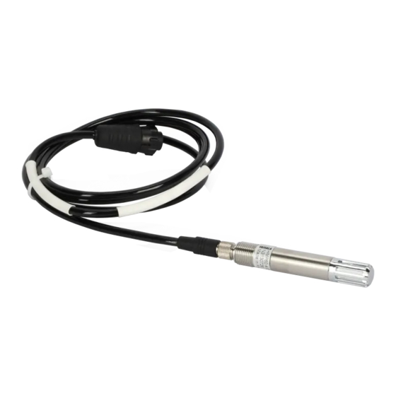
Page 13: Figure 1 Hmp60 And Hmp110 Series Probes
IP54 rated probe with PC/ABS plastic housing and HUMICAP® 180R sensor. Lightweight probe with higher accuracy and faster thermal response time. Not for permanent outdoor use. Two analog output channels. Used with the Vaisala HM40 hand-held meter (requires special software configuration). VAISALA ________________________________________________________________________ 11... -
Page 14: Basic Features And Options
- Plastic M12 installation nuts for HMP60, HMP110, HMP110D and HMP110T. - Plastic locking bushing for HMP63 and HMP113 (for use with Vaisala products, for example HM40 hand-held meter). 12 ___________________________________________________________________ M211060EN-G... -
Page 15: Filter Options
Diameter Pore Size Plastic membrane filter 12 mm 0.2 µm Plastic grid filter for (portable use only, 12 mm fastest response time) Porous PTFE filter 12 mm 8 µm Stainless steel sintered filter 12 mm 38 µm VAISALA ________________________________________________________________________ 13... -
Page 16: Installation Accessories (Optional)
User's Guide _______________________________________________________________________ Installation Accessories (Optional) For order codes, see section Options and Accessories on page 72. Probe Mounting Clamp The optional mounting clamp makes it easy to install the probe on the wall of the measurement environment. The probe can be detached for calibration simply by loosening the lower screw. -
Page 17: Figure 6 Sliding The Lower Clamp Part
Place the clamp to the intended location and secure the upper clamp part with a screw. See Figure 7 below. 1209-003 Figure 7 Securing the Upper Clamp Part Place the probe in the clamp. Tighten the lower clamp part with a screw. VAISALA ________________________________________________________________________ 15... -
Page 18: Probe Mounting Flange
Plastic Locking Bushing for HMP63 and HMP113 HMP63 and HMP113 can be connected to compatible Vaisala instruments using a plastic locking bushing that is placed over the probe. The bushing has a M15x1 thread. It is compatible with the HMT120 and HMT130 transmitters, and the HM40 hand-held meter. -
Page 19: Duct Installation Kit For Hmp60, Hmp110, Hmp110D And Hmp110T
Duct Installation Kit for HMP60, HMP110, HMP110D and HMP110T The duct installation kit includes a plastic pipe with a flange (Vaisala order code: 215619). To install the probe with the duct installation kit, drill a hole to the duct wall, assemble the probe to the duct installation kit, slide the probe head through the hole, and attach the flange to the duct wall with four screws. -
Page 20: Loop Power Converter
User's Guide _______________________________________________________________________ Loop Power Converter The loop power converter is an open frame module that converts one 0 ... 2.5 VDC voltage output to a 4 ... 20 mA current output. To use the loop power converter module, the probe: - must be in the analog output mode - the desired quantity is on channel 1 - channel 1 must be scaled to 0 ... -
Page 21: Cables
The USB Serial Interface Cable has a straight, threaded female M8 connector on one end, and a USB Type A male plug on the other. The USB cable is intended for maintenance purposes only, not for permanent installation. 1210-062 Figure 13 USB Serial Interface Cable VAISALA ________________________________________________________________________ 19... -
Page 22: Chapter 3 Installation
User's Guide _______________________________________________________________________ CHAPTER 3 INSTALLATION This chapter provides you with information that is intended to help you install the HMP60 and HMP110 series probes. NOTE Before you connect an HMP60 or HMP110 series probe to a device, it is recommended to power off the device. -
Page 23: Dimensions For Hmp63 And Hmp113
Chapter 3 ________________________________________________________________ Installation Dimensions for HMP63 and HMP113 0912-103 Figure 16 HMP63 and HMP113 Dimensions 73.5 0912-102 Figure 17 HMP63 and HMP113 with Plastic Locking Bushing, Dimensions VAISALA ________________________________________________________________________ 21... -
Page 24: Mounting The Hmp60, Hmp110, Hmp110D And Hmp110T Probes
User's Guide _______________________________________________________________________ Mounting the HMP60, HMP110, HMP110D and HMP110T Probes HMP60, HMP110, HMP110D and HMP110T are designed to be mounted from the M12 thread on the probe body or from the smooth part of the probe body. For a convenient installation, use the optional installation accessories: - Use the plastic mounting nuts to hold the probe in a through-wall installation. -
Page 25: Drilling Instructions For Duct Installation Kit
Drill holes for the duct installation kit mounting screws around the hole in a square arrangement, 42 mm apart from each other. Use a 3.2-mm drill bit to drill the holes for the mounting screws (four ST4.2×16-C-Z DIN 7981 screws). VAISALA ________________________________________________________________________ 23... -
Page 26: Mounting The Hmp63 And Hmp113 Probes
User's Guide _______________________________________________________________________ Mounting the HMP63 and HMP113 Probes HMP63 and HMP113 probes do not have a thread on the probe body. For a convenient installation, use the optional installation accessories: - Use the probe mounting clamp to hold the probe on a wall. - Use the probe mounting flange to hold the probe in a through-wall installation. -
Page 27: Wiring
Grounding method HMP63 and HMP113 It is recommended to use a shielded cable and connect the shield to ground. In the shielded cables supplied by Vaisala, the threaded connector connects the shield to the probe housing. HMP60, HMP110, There are two ways to ground the probe depending HMP110D, HMP110T, on installation type. -
Page 28: Table 5 Pinout Of The Probe Connector
User's Guide _______________________________________________________________________ Table 5 Pinout of the Probe Connector HMP60 / HMP63 / HMP110 / HMP110D / Wire HMP113 / HMP110T HMP110REF color 5 ... 28 VDC (V 0 ...1 / 0 ... 2.5 V) 5 ... 28 VDC Brown 8 ... -
Page 29: Wiring With The Loop Power Converter
8 ... 28 VDC. The operating voltage for the probe (5 VDC) is delivered by the module. For more information, see the Loop Power Converter Quick Reference Guide. 1210-031 Figure 22 Wiring with the Loop Power Converter Module VAISALA ________________________________________________________________________ 27... -
Page 30: Power Supply Requirements
User's Guide _______________________________________________________________________ Power Supply Requirements The operating voltage for the HMP60 and HMP110 series probes must be in the following range: Table 6 Operating Voltage Ranges HMP60 / HMP63 / HMP110 / HMP113 / HMP110D / HMP110REF HMP110T 5 ... 28 VDC (V 0 ...1 / 0 ... -
Page 31: Operation
57600 bits/s. There is no internal termination for the RS-485 on the probe. Use of termination resistors is not recommended. If the resistors are used, the possible increase in current consumption should be taken into account. VAISALA ________________________________________________________________________ 29... -
Page 32: Connecting To The Serial Interface
22. For temporary use of the serial interface (for example, calibration), you can use the optional USB cable (Vaisala order code: 219690). Before you can use the USB cable, you must install the provided USB driver on your PC, see Installing the Driver for the USB Cable on page 30. -
Page 33: Installing The Driver For The Usb Cable
COM port. There is no reason to uninstall the driver for normal use. However, if you wish to remove the driver files and all Vaisala USB cable devices, you can do so by uninstalling the entry for Vaisala USB Instrument Driver from the Programs and Features menu in the Windows Control Panel. -
Page 34: Terminal Application Settings For Digital Probes
Select the Serial settings category, and check that the correct COM port is selected in the Serial line to connect to field. You can check which port the USB cable is using with the Vaisala USB Instrument Finder program that has been installed in the Windows Start menu. -
Page 35: Figure 23 Putty Terminal Application
Chapter 4 _________________________________________________________________ Operation 0807-004 Figure 23 PuTTY Terminal Application VAISALA ________________________________________________________________________ 33... -
Page 36: Accessing Serial Line Command Interface (Rs-485 Mode) From Analog Or Modbus Mode
Select the Serial settings category, and check that the correct COM port is selected in the Serial line to connect to field. You can check which port the USB cable is using with the Vaisala USB Instrument Finder program that has been installed in the Windows Start menu. -
Page 37: Modbus Communication
HMP 60 and HMP110 series. Address 0 cannot be used on Modbus. *** Extra response delay can be used, for example, to avoid problems caused by direction-switching delays in bus converters. NOTE The instrument must be switched off and on before the communication setting changes take effect. VAISALA ________________________________________________________________________ 35... -
Page 38: List Of Serial Commands
User's Guide _______________________________________________________________________ List of Serial Commands All commands can be issued either in uppercase or lowercase. In the command examples, the keyboard input by the user is in bold type. The notation <cr> refers to pressing the carriage return (Enter) key on your computer keyboard. -
Page 39: Device Information And Status
If the probe is in poll mode, but a connection has not been opened using the OPEN command, issue the ?? command. For a description of the serial interface modes, see section Set Serial Line Settings on page 40. ??<cr> VAISALA ________________________________________________________________________ 37... -
Page 40: View Calibration Information
Examples: cdate Cal. date : 20150109 ctext Cal. info : VAISALA/HEL Enter Calibration Information To enter the calibration date, use the CDATE command ( cdate ). To enter a text string with information about the [YYYYMMDD] calibration, use the CTEXT command ( ctext [string] CDATE [yyyymmdd] <cr>... -
Page 41: View Serial Number
T= 22.6 'C RH= 22.8 %RH Td= 0.3 'C T= 22.6 'C RH= 22.5 %RH Td= 0.2 'C T= 22.6 'C RH= 22.5 %RH Td= 0.2 'C … Example (HMP110T): T= 22.6 'C T= 22.6 'C T= 22.6 'C … VAISALA ________________________________________________________________________ 39... -
Page 42: Stop Measurement Output
User's Guide _______________________________________________________________________ Outputting the results continues in intervals issued with the command INTV. You can stop the output by entering the S command. Stop Measurement Output Use the S command or press the Esc key to stop the continuous measurement output. -
Page 43: Set Serial Interface Mode
Special serial interface mode that is only used for interoperability with Vaisala devices such as HMT120, HMT130, and HM40. This mode is set at Vaisala for probes that are ordered for such use. ANALOG No serial line, analog outputs active. For instructions on how to... -
Page 44: Set Output Interval
User's Guide _______________________________________________________________________ In the RUN mode, the probe may send the measurement data message NOTE right as you are typing the S command to stop the sending. Therefore, you may need to repeat the S command. This must be noted especially when designing computer programs to access the probe. -
Page 45: Set Probe Address
Use the SDELAY command to view or set the serial interface answer minimum delay. SDELAY [delay]<cr> where delay Range 0 ... 255. Value corresponds to four milliseconds (for example, 5 = 0.020 second minimum answer delay) Example: sdelay Serial delay sdelay 50 Serial delay VAISALA ________________________________________________________________________ 43... -
Page 46: Set Measurement Units
User's Guide _______________________________________________________________________ Set Measurement Units Use the UNIT command to view or set the measurement units that are used in the serial line measurement messages. UNIT [M/N]<cr> M is for metric units, N is for non-metric units. Quantity Metric Unit Non-Metric Unit ºC ºF... -
Page 47: Calibration Commands
Remember to allow the humidity to stabilize for 20 - 40 minutes after changing the reference. Example: two-point calibration with LiCl (11 %RH) and NaCL (75 %RH) references: 11.2684 1. ref ? 11 Press any key when ready ... 75.0612 2. ref ? 75 VAISALA ________________________________________________________________________ 45... -
Page 48: Clear Adjustment Of Rh Measurement
User's Guide _______________________________________________________________________ Clear Adjustment of RH Measurement Use the CRHCLR command to clear the adjustment of RH measurement that has been done using the CRH command. This command is not available on the HMP110T. CRHCLR<cr> Example: crhclr Calibrate Temperature Measurement Use the CT command to perform a one-point or two-point temperature (T) calibration. -
Page 49: Clear Adjustment Of T Measurement
- Cp offset and gain: capacitance, calibrated using the CRH command - T offset and gain: calibrated using the CT command Example (shows default values, no user calibration done): Cp offset : 0.00000000E+00 Cp gain 1.00000000E+00 offset : 0.00000000E+00 gain 1.00000000E+00 VAISALA ________________________________________________________________________ 47... -
Page 50: Other Commands
User's Guide _______________________________________________________________________ Other Commands Set Analog Output Mode Use the AMODE command to show or set the operation mode of the analog output. This command is not available on the HMP110D. AMODE [ch1] [ch2]<cr> where ch1 = Analog output mode for channel 1, range 0 ...3. The options are: 0 (0 ... -
Page 51: Set Analog Output Parameters And Scaling
1 to -40 ... 60 °C when prompted): asel t rh Ch1 T -20.00 'C ? -40 Ch1 T 80.00 'C ? 60 Ch2 RH 0.00 %RH ? Ch2 RH 100.00 %RH ? VAISALA ________________________________________________________________________ 49... -
Page 52: Set Analog Output Error Indication Level
User's Guide _______________________________________________________________________ Set Analog Output Error Indication Level If the device is malfunctioning, the analog output is set to a specified level. This overrides the normal measurement output of the channel. The default error level is 0 V, or another value predefined by the customer when ordering the device. -
Page 53: Extend Analog Output Range
RHLIMIT [max_rh]<cr> where max_rh = Maximum reading of the RH parameter. The possible values are 100.0 … 120.0. The default value is 100.0. Example (extend the maximum RH reading to 120%): rhlimit 120 Max. RH % 120.0 %RH VAISALA ________________________________________________________________________ 51... -
Page 54: Display Command List
User's Guide _______________________________________________________________________ Example (on analog output, extend the maximum RH reading to 120% and scale the RH output on channel 2 from (0…1 V) 0...100% to (0…1 V) 0…120%): rhlimit 120 Max. RH % 120.0 %RH asel ? Ch1 T -20.00 'C ? Ch1 T 80.00 'C ? -
Page 55: Close The Connection In Poll Mode
Use the FRESTORE command to restore the factory settings to the probe. All user settings, including the user-performed calibration corrections, will be lost. The probe will revert back to the factory calibrated settings. FRESTORE<cr> Example: frestore Factory settings restored VAISALA ________________________________________________________________________ 53... -
Page 56: Chapter 5 Maintenance
- HMP60 and HMP63: change the INTERCAP® sensor. - HMP110 and HMP113: adjust the measurement yourself, or have it adjusted at a Vaisala Service Center. Light cleaning of the probe, and replacement of the filter should be done only when necessary. -
Page 57: Calibration Procedure
Chapter 5 _______________________________________________________________ Maintenance New filters can be ordered from Vaisala. For available filters, see section Filter Options on page 13. The order codes of the filters are listed in section Options and Accessories on page 72. Calibration Procedure To calibrate your probe, you need a known stable humidity or temperature reference, and a way to read the output of the probe (analog output, serial output, or the MI70 indicator). -
Page 58: Adjustment Procedure Using Serial Line (Hmp110, Hmp110D And Hmp113)
To perform a one-point adjustment to the capacitance measurement of the HMP110, HMP110D or HMP113 using serial line, you need: - The Vaisala USB cable (Vaisala order code: 219690) - PC with a terminal application. - One humidity reference. One-point adjustment with a single <... -
Page 59: Two-Point Adjustment Of Rh Measurement (Hmp110, Hmp110D And Hmp113)
To perform a two-point adjustment to the capacitance measurement of the HMP110, HMP110D or HMP113 using serial line you need: - The Vaisala USB cable (Vaisala order code: 219690) - PC with a terminal application. - Two humidity references. The first point requires a < 50 %RH humidity reference, the second point must be >... - Page 60 User's Guide _______________________________________________________________________ Wait for 20 – 40 minutes for the humidity to stabilize. Start the terminal session and connect the USB cable to the probe. If your probe is in the analog output mode, you need to press Enter a few times to start it in RS-485 mode.
-
Page 61: One-Point Adjustment Of T Measurement (Hmp110, Hmp110D, Hmp113, And Hmp110T)
To perform a one-point adjustment to the temperature measurement of the HMP110, HMP110D, HMP113, or HMP110T using serial line you need: - The Vaisala USB cable (Vaisala order code: 219690) - PC with a terminal application. - One known and stable temperature reference. -
Page 62: Adjustment Procedure Using Mi70 Indicator (Hmp110, Hmp110D And Hmp113)
User's Guide _______________________________________________________________________ Use the ERRS command to see that no errors are active: errs Give the CT command, with the temperature value of the reference as a parameter: ct 23.5 Check with the L command that the user adjustment parameters have changed. -
Page 63: One-Point Adjustment Of Temperature Measurement
In a 1-point adjustment, make sure the reference condition represents the measuring environment. To perform a one-point adjustment to the temperature measurement of the HMP110, HMP110D or HMP113 using the MI70 indicator, you need: - MI70 indicator. - Connection cable for MI70 indicator (219980). VAISALA ________________________________________________________________________ 61... - Page 64 User's Guide _______________________________________________________________________ - One known and stable temperature reference. Connect the probe to Port I of the MI70 indicator. Turn on the MI70 indicator. Start the adjustment sequence from Main menu > Functions > Adjustments. MI70 notifies you that automatic power off is disabled during adjustment mode, press OK to acknowledge.
-
Page 65: Repair Maintenance
Pull out the old INTERCAP® sensor and insert a new one. Refer to Figure 25 below. Handle the new sensor by the plastic frame. DO NOT TOUCH THE SENSOR PLATE. 1210-034 Figure 25 Removing the Sensor Attach a new filter on the probe. VAISALA ________________________________________________________________________ 63... -
Page 66: Changing The Humicap® 180R Sensor (Hmp110, Hmp110D And Hmp113)
User's Guide _______________________________________________________________________ Changing the HUMICAP® 180R Sensor (HMP110, HMP110D and HMP113) NOTE Replacing the humidity sensor of the HMP110, HMP110D and HMP113 is not necessary in normal operation. If the accuracy of the probe does not seem to be within specification, it is likely that the accuracy can be restored by performing the adjustment procedure. -
Page 67: Chapter 6 Troubleshooting
Set Analog Output Error Indication Level on page 50. Solving Typical Problems You can check the error message via the serial interface by using the ERRS command. If you are unable to remove the errors, contact Vaisala technical support. See section Technical Support on page 66. Table 13... -
Page 68: Technical Support
Contact Vaisala technical support. Technical Support For technical questions, contact the Vaisala technical support by e-mail at helpdesk@vaisala.com. Provide at least the following supporting information: - Name and model of the product in question - Serial number of the product... -
Page 69: Chapter 7 Technical Data
0 ... +40 °C when dewpoint depression* < 15 °C ±2 °C temperature range -40 ... 0 °C and +40 ... +60 °C when dewpoint depression* < 10 °C ±3 °C *dewpoint depression = ambient temperature - dewpoint VAISALA ________________________________________________________________________ 67... -
Page 70: Performance (Hmp110 And Hmp110D)
90 ... 100 %RH ±4.0 %RH Factory calibration uncertainty (+20 °C) 0 … 90%RH ±1.1 %RH 90 … 100%RH ±1.8 %RH Humidity sensor Vaisala HUMICAP® 180R Stability ±2 %RH over 2 years Response time (t90) with plastic grid filter approx. 17 s with membrane filter approx. -
Page 71: Performance (Hmp113)
0 ... 90 %RH ±3.0 %RH 90 ... 100 %RH ±4.0 %RH Factory calibration uncertainty (+20 °C) ±1.5 %RH Humidity sensor Vaisala HUMICAP® 180R Stability ±2 %RH over 2 years Temperature Measurement range -40 ... +60 °C Accuracy over temperature range 0 ... -
Page 72: Operating Environment
User's Guide _______________________________________________________________________ Operating Environment Operating temperature range HMP60 -40 ... +60 °C HMP63 -40 ... +60 °C HMP110 -40 ... +80 °C HMP113 -40 ... +60 °C HMP110D -40 ... +80 °C HMP110T -40 ... +80 °C Operating humidity range 0 ... -
Page 73: Mechanics (Hmp60, Hmp110, Hmp110D And Hmp110T)
Materials body PC/ABS blend grid filter PC (glass reinforced) cable Polyurethane of FEP Housing classification IP54 Cable connector 4-pin M8 (IEC 60947-5-2) Cable lengths 0.3 and 3 m Weight probe probe with 0.3 m cable 20 g VAISALA ________________________________________________________________________ 71... -
Page 74: Options And Accessories
Table 14 Options and Accessories Description Item Code Sensors ● ● Vaisala INTERCAP® sensor, 1 piece 15778HM ● ● Vaisala INTERCAP® sensor, 10 pcs INTERCAPSET-10PCS ● ● ● HUMICAP180R Vaisala HUMICAP® 180R sensor Sensor protection ●... -
Page 75: Appendix Amodbus Reference
See Table 17 on page 74 for available registers. 43 14 2B 0E Read Device Identification See Table 18 on page 76 for available device identification objects. NOTE After power-up, wait for two seconds before sending Modbus requests. VAISALA ________________________________________________________________________ 73... -
Page 76: Modbus Register Map
User's Guide _______________________________________________________________________ Modbus Register Map Table 17 Modbus Register Map (Measurement Values and Settings) Logical PDU Address Register Description Data Format Register Notes Address (hexadecimal) Type (decimal) 00 00 RH (measured) * 32-bit float read-only 00 01 00 02 T (measured) 32-bit float read-only... - Page 77 Modbus mode by switching to the serial line mode as instructed in Accessing Serial Line Command Interface (RS-485 Mode) from Analog or Modbus Mode on page 34 and entering correct settings with serial line commands. VAISALA ________________________________________________________________________ 75...
-
Page 78: Device Identification Objects
Communication test registers can be used to find the correct Modbus master configuration for the data types and the byte order of the Vaisala device. Test registers are also useful for testing if the register addresses should be specified as 1-based logical or 0-based PDU addresses on the master. - Page 79 *M211060EN*...
Need help?
Do you have a question about the HMP60 series and is the answer not in the manual?
Questions and answers