Vaisala WINDCAP WMT700 Series User Manual
Ultrasonic wind sensor
Hide thumbs
Also See for WINDCAP WMT700 Series:
- User manual (221 pages) ,
- Quick reference manual (36 pages) ,
- Technical notes (4 pages)
Table of Contents
Advertisement
Advertisement
Table of Contents

Related Manuals for Vaisala WINDCAP WMT700 Series


Summary of Contents for Vaisala WINDCAP WMT700 Series
- Page 1 M211095EN-H User Guide Vaisala WINDCAP® Ultrasonic Wind Sensor Series WMT700...
- Page 2 This product contains software developed The contents of this manual are subject to by Vaisala or third parties. Use of the change without prior notice. software is governed by license terms and Local rules and regulations may vary and...
-
Page 3: Table Of Contents
Table of Contents Table of Contents About This Document..................9 Version Information....................9 Documentation Conventions................9 Trademarks......................10 Product Overview....................11 Introduction to WMT700..................11 Regulatory Compliances..................17 Ordering Options....................18 2.3.1 Measurement Range..................19 2.3.2 Temperature Range..................19 2.3.3 Heating......................20 2.3.4 Digital Communication Interface..............20 2.3.5 Digital Communication Profile..............21 2.3.6... - Page 4 WMT700 User Guide M211095EN-H Serial Communication and Analog Output............39 Serial Communication..................40 3.7.1 Communication Interface................40 3.7.2 Profiles......................40 3.7.3 Protocols......................41 3.7.4 Measurement and Configuration Modes............. 41 3.7.5 Serial Interface Timing..................42 Analog Output..................... 43 3.8.1 Analog Output Types................... 43 3.8.2 Analog Output Scaling.................
- Page 5 Table of Contents Configuration...................... 101 Parameter Handling Commands..............102 5.4.1 S — Set Parameter..................103 5.4.2 G — Get Parameter..................104 5.4.3 BAUD — Display or Set Port Settings............105 Wind Measurement Control Commands............106 5.5.1 MEAS — Single Wind Measurement............106 5.5.2 START — Start Continuous Measurement..........106 5.5.3 STOP —...
- Page 6 WMT700 User Guide M211095EN-H 5.24 WS425 A/B ASCII Profile.................. 147 5.24.1 WS425 A/B ASCII Commands..............148 5.25 WS425 A/B WAT11 Profile.................150 5.25.1 WS425 A/B WAT11 Commands..............151 5.26 SDI-12 Profile (v 1.3).................... 151 5.26.1 SDI-12 Commands..................153 5.27 SDI-12 Data Messages..................160 5.27.1 WS425 A/B SDI-12 Message for C and M Command......
- Page 7 List of Figures List of Figures Figure WMT700 Wind Sensor..................12 Figure 2 WMT700 from Below..................13 Figure 3 FIX70 Mounting Kit...................14 Figure 4 WS425FIX60-POM....................15 Figure 5 WMT700FIX60-POM..................15 Figure 6 WS425FIX60-RST and WS425FIX60............16 Figure 7 WMT700FIX60-RST..................16 Figure 8 Example of WMT703 Configuration............26 Figure 9 Bird Cage......................27 Figure 10...
- Page 8 WMT700 User Guide M211095EN-H Figure 49 System Environment with Serial Port COM1 Only........183 Figure 50 System Environment with Analog Output Only........183 Figure 51 System Environment with Serial Ports COM1 and COM2..... 184 Figure 52 System Environment with Backup Battery..........184 Figure 53 Complete Set of WMT700 Accessories............
- Page 9 List of Tables List of Tables Table Document Versions....................9 Table 2 Environmental Tests....................17 Table 3 Electromagnetic Compatibility Tests............. 17 Table 4 Ordering Options....................18 Table 5 Measurement Ranges of Different Sensor Types........19 Table 6 Temperature Range.................... 19 Table 7 Heating........................20 Table 8 Digital Communication Interface..............
- Page 10 WMT700 User Guide M211095EN-H Table 52 Checksum Table....................146 Table 53 WS425 A/B ASCII Commands...............148 Table 54 Configurable Parameters for WS425 A/B WAT11 Profile......151 Table 55 Configurable Parameters................152 Table 56 SDI-12 Commands..................... 153 Table 57 Error and Event Messages................169 Table 58 Restored Serial Port Settings................171 Table 59...
-
Page 11: About This Document
Chapter 1 – About This Document 1. About This Document 1.1 Version Information Table 1 Document Versions Document Code Date Description M211095EN-H April 2017 Added 3 new commands for WS425 F/G ASOS protocol. Added information about the new ASOS adapter. M211095EN-G February 2017 Previous version 1.2 Documentation Conventions DANGER! -
Page 12: Trademarks
M211095EN-H 1.3 Trademarks Vaisala â and WINDCAP â is a registered trademark of Vaisala Oyj. Windows â is a registered trademark of Microsoft Corporation in the United States and/or other countries. All other product or company names that may be mentioned in this publication are trade... -
Page 13: Product Overview
The WMT700 series wind sensors are based on the advanced, patented Vaisala WINDCAP wind measurement technology that ensures accurate results in all wind directions. The effects of temperature, humidity, and pressure are fully compensated. -
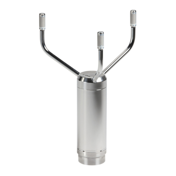
Page 14: Wmt700 Wind Sensor
WMT700 User Guide M211095EN-H Figure 1 WMT700 Wind Sensor The array consists of 1, 8, and 9. Top of WMT700 with North arrow Orange sticker marking North arm Hot warning sticker Type label Mounting screw Mounting adapter Body Transducer arms (3 pcs) Transducers (3 pcs) -
Page 15: Figure 2 Wmt700 From Below
Chapter 2 – Product Overview Figure 2 WMT700 from Below Mounting adapter screw (3 pcs; use 4-mm Allen key) 17-pin M23 male connector Waterproof vent Do not open the sensor. There are no user-serviceable parts inside. -
Page 16: Figure 3 Fix70 Mounting Kit
WMT700 User Guide M211095EN-H Figure 3 FIX70 Mounting Kit Fix body Removable mast guide with mounting hardware Mounting hardware (M6 nuts, washers) U bolts for Ø 30 mm mast (2 pcs) U bolts for Ø 60 mm mast (2 pcs) -
Page 17: Figure 4 Ws425Fix60-Pom
Chapter 2 – Product Overview Figure 4 WS425FIX60-POM Clamp Label Figure 5 WMT700FIX60-POM Clamp Label... -
Page 18: Figure 6 Ws425Fix60-Rst And Ws425Fix60
WMT700 User Guide M211095EN-H Figure 6 WS425FIX60-RST and WS425FIX60 Label Clamp Figure 7 WMT700FIX60-RST Label Clamp... -
Page 19: Regulatory Compliances
Chapter 2 – Product Overview 2.2 Regulatory Compliances Vaisala WINDCAP Ultrasonic Wind Sensor WMT701, WMT702, WMT703, and WMT704 comply with the performance and environmental test standards listed below. Table 2 Environmental Tests Test Setup According to Wind driven rain MIL-STD 810G Method 506.5... -
Page 20: Ordering Options
WMT700 User Guide M211095EN-H Test Setup According to Radiated emissions CISPR 22 RF field immunity IEC 61000-4-3 Insulation resistance IEC 60092-504 Limits according to IEC 60945: Maritime navigation and radiocommunication equipment and systems - General requirements - Methods of testing and required test results. 4th edition, 2002-08. See G. -
Page 21: Measurement Range
-10 ... +60 °C -40 ... +60 °C -55 ... +70 °C The temperature range is not connected to heating in any way. If you operate in a demanding environment where ice accumulation is expected, Vaisala recommends using a heated sensor. -
Page 22: Heating
Heated transducers (Min. 30 W power supply is needed) Heated transducers and arms (Min. 150 W needed) Heated transducers, arms, and body (Min. 250 W needed) Vaisala recommends using heated versions of WMT700 in environmental conditions where snow and ice build-up is possible. 2.3.4 Digital Communication Interface Ordering option 4 defines the serial line physical interface. -
Page 23: Digital Communication Profile
Chapter 2 – Product Overview 2.3.5 Digital Communication Profile Ordering option 5 defines the used communication protocol. WS425 options are usable and backwards compatible when replacing a WS425 sensor with a WMT700 unit. Other application or customer-specific user profiles are also available. Table 9 Digital Communication Profile Option Communication Profile... -
Page 24: Table 11 Output Configuration
WMT700 User Guide M211095EN-H Table 11 Output Configuration Option Output Configuration Disabled Voltage output 100 mV/m/s 0 mV = 0 m/s 4000 mV = 40 m/s (WMT701 maximum wind speed) 6500 mV = 65 m/s (WMT702 maximum wind speed) 7500 mV = 75 m/s (WMT703 maximum wind speed) 9000 mV = 90 m/s (WMT704 maximum wind speed) Current output 4 …... -
Page 25: Analog Output Signal For Wind Direction Channel
Chapter 2 – Product Overview Option Output Configuration WS425 frequency output 5 Hz/mph 0 Hz = 0 m/s 447.5 Hz = 89.5 mph (WMT701 maximum wind speed) 725 Hz = 145 mph (WMT702 maximum wind speed) 840 Hz = 168 mph (WMT703 maximum wind speed) 1006.5 Hz = 201.3 mph ( WMT704 maximum wind speed) Push up output, 10 Hz/m/s 0 Hz = 0 m/s... -
Page 26: Connection Cables
WMT700 User Guide M211095EN-H Selection Output Configuration Current output 4 … 20 mA (44.444 uA/degree) 4 mA = 0 degree 20 mA = 360 degree km/h WS425 Potentiometer output 0% of V = 0 degree 100% of V = 360 degree More Information ‣... -
Page 27: Accessories
Chapter 2 – Product Overview Table 14 Mounting Adapters Option Adapter Type Adapter 228869 only. Standard adapter, no fix Adapter 228869 with WMT70FIX70 fixing mechanics. Also suitable for inverted mounting. Standard adapter for general purpose Adapter 228869 with WMT700FIX60-POM. Standard adapter with plastic fix for 60 mm pole Adapter 228869 with WMT700FIX60-RST Standard adapter with stainless steel fix for 60 mm pole... -
Page 28: Example Of Wmt703 Configuration
WMT700 User Guide M211095EN-H Option Manual Chinese manual Russian manual 2.3.13 Example of WMT703 Configuration Figure 8 Example of WMT703 Configuration More Information ‣ Heating (page 48) 2.4 Accessories WMT700 can be tailored to your needs with several accessories. The accessories include: • Mounting adapters for different mast diameters •... -
Page 29: Bird Cage
Chapter 2 – Product Overview 2.4.1 Bird Cage Figure 9 Bird Cage Vaisala recommends using the optional bird cage (WMT70BirdKit) in areas with large bird populations. The cage is designed to prevent large birds from disturbing the wind speed and direction measurements. -
Page 30: Cables
MAWS cable 10 m Used for connecting WMT700 to Vaisala Automatic Weather Station MAWS. 229807SP AWS520 cable 10 m, shield connected Used for connecting WMT700 to Vaisala Fixed Site to PE pin Observation System AWS520. 227566SP AWS520 cable 10 m, shield not... -
Page 31: Cable Tightening Tool
Chapter 2 – Product Overview 2.4.4 Cable Tightening Tool Figure 11 Cable Tightening Tool WMT700 is shipped with a cable tightening tool (237888SP). When you insert a cable in the cable tightening tool, it is easier to grip and rotate. After tightening, you can leave the cable tightening tool in place. - Page 32 WMT700 User Guide M211095EN-H...
-
Page 33: Functional Description
Chapter 3 – Functional Description 3. Functional Description 3.1 Operating Principle WMT700 uses the Vaisala WINDCAP ultrasonic sensor technology in wind measurement. The sensor has an onboard microcontroller that captures and processes data and communicates over serial interfaces. The wind sensor has an array of three equally spaced ultrasonic transducers on a horizontal plane. -
Page 34: Figure 12 Ultrasonic Measurement Principle
WMT700 User Guide M211095EN-H Figure 12 Ultrasonic Measurement Principle Ultrasonic measurement with zero wind Impact of tail wind on ultrasonic measurement Impact of head wind on ultrasonic measurement The microcontroller calculates WS from the measured transit times using the following formula:... -
Page 35: Figure 13 Measurement Paths Of Wmt700
Chapter 3 – Functional Description =0.5·L·(1/t -1/t Wind velocity Distance between two transducers Transit time in the forward direction Transit time in the reverse direction Measuring the six transit times allows V to be computed for each of the three ultrasonic paths. -
Page 36: Coordinate Systems: Vector And Polar Calculations
WMT700 User Guide M211095EN-H The equation depends on the accurate distance of the measurement path (L). The computed wind speeds are independent of altitude, temperature, and humidity, which are canceled out when the transit times are measured in both directions, although the individual transit times depend on these parameters. -
Page 37: Wind Speed And Direction Averaging
Chapter 3 – Functional Description Figure 14 Wind Speed and Direction Presentations (Direction Offset Is 0) More Information ‣ Analog Output Signal for Wind Speed Channel (page 21) 3.3 Wind Speed and Direction Averaging WMT700 provides average values for wind speed and direction using either scalar or vector averaging. -
Page 38: Scalar Averaging
WMT700 User Guide M211095EN-H 3.3.1 Scalar Averaging When you select scalar averaging, WMT700 calculates wind speed and direction averages by adding up each wind measurement from the averaging time and dividing the sum by the number of measurements. The time between each consecutive wind speed and wind direction measurement is 0.25 seconds. -
Page 39: Wind Direction Coasting
Chapter 3 – Functional Description Figure 15 Example of Wind Direction Averaging 3.3.2 Wind Direction Coasting Accurate wind direction measurement requires that the wind speed is sufficient. If you enable wind direction coasting, WMT700 does not calculate wind direction when the wind speed drops below the selected wind direction coasting threshold. -
Page 40: Measurement Methods
WMT700 User Guide M211095EN-H 3.4 Measurement Methods WMT700 measures wind speed and direction either continuously or for the duration of the user-configurable averaging time. You can select the measurement mode over the serial interface. 3.4.1 Continuous Measurement You can set WMT700 to measure wind data continuously and stop the measurement with the STOP command. -
Page 41: Serial Communication And Analog Output
Chapter 3 – Functional Description You can set WMT700 to send measurement data either as analog output or data messages through a serial port, or you can use both outputs simultaneously. You can send operating and configuring commands to WMT700 through the serial interface. Operation and heating power is usually provided from one power supply. -
Page 42: Serial Communication
WMT700 User Guide M211095EN-H • Analog output signals for wind speed channel (AOUT1) • Analog output signals for wind direction channel (AOUT2) 3.7 Serial Communication In WMT700, there are two serial communication ports: • COM1: Service port (RS-485) • COM2: Configurable digital communication interface Both ports support the same commands, protocols, operations, and data messages. -
Page 43: Protocols
WMT700. The ROSA - MES12 profile is intended for connecting WMT700 to the Vaisala ROSA system. The WS425 profiles can be used when upgrading from WS425 to WMT700. -
Page 44: Serial Interface Timing
WMT700 User Guide M211095EN-H Figure 17 Configuration and Measurement Modes After power-up, WMT700 is in measurement mode. More Information ‣ Command Set for WMT700 (page 181) ‣ Entering and Exiting Configuration Mode (page 100) ‣ OPEN — Entering Configuration Mode (page 100) ‣... -
Page 45: Analog Output
Chapter 3 – Functional Description • Interfaces RS-232, RS-485, RS-422: The figure below shows timing when WMT700 is polled in the measurement mode. Figure 18 Timing for RS-232, RS-485, and RS-422 Interfaces The response delay t2 is user-configurable. In the configuration mode, some commands have a longer response delay. -
Page 46: Figure 19 Frequency Output
WMT700 User Guide M211095EN-H • Frequency output • Push-pull output • Pull-down output • Pull-up output Analog output for Wind Direction (Aout2) can be configured as: • Voltage output • Current output • Potentiometer output Figure 19 Frequency Output... -
Page 47: Analog Output Scaling
Chapter 3 – Functional Description 3.8.2 Analog Output Scaling You can specify the transfer function between measured values and output analog values. You can select the analog output type as well as the gain and offset used in the transfer function. Table 18 Factory Settings for Analog Wind Speed Output Aout1 Selected Option Scaling/Gain... -
Page 48: Table 20 Common Transfer Function Settings For Aout1 (Ws)
WMT700 User Guide M211095EN-H Aout2 Selected Scaling/Gain Offset Error Indication Example Option Current 0 … 20 mA 0.00005 A/° 0.022 A 0 mA = 0° 18 mA = 360° Current 4 … 20 mA 000044444 A/° 0.004 A 0.002 A 4 mA = 0°... -
Page 49: Limitations For Output Signals
Chapter 3 – Functional Description You can configure output scaling or transfer function settings in a variety of ways by changing the custom gain and offset. The basic measurement units are m/s and degrees. The physical output units are V, A, and Hz. For the potentiometer, an output of 1 means 100% of the Aout ref voltage. -
Page 50: Missing Readings And Error Indication
WMT700 User Guide M211095EN-H Example To limit the output 1 in voltage mode to a range of 0.1 … 5 V, set the analog output minimum value to 0.1 and the analog output maximum value to 5. Type the following commands: S aout1minv,0.1 S aout1maxv,5 3.8.4 Missing Readings and Error Indication... -
Page 51: Heated Transducers
Chapter 3 – Functional Description In addition to the standard non-heated version, WMT700 can be preconfigured at the factory according to your order: • Heating for the transducers only • Heating for both transducers and array arms • Heating for body, transducers, and array arms Make sure that the supply output power capacity is high enough especially when transducers, array arms, and sensor body are equipped with heaters. -
Page 52: Heated Body, Transducers, And Arms
WMT700 User Guide M211095EN-H 3.9.3 Heated Body, Transducers, and Arms WARNING! To avoid injury, do not touch the heated parts of the wind sensor when the heating is enabled. The fully heated version of WMT700 is suitable for harsh weather conditions. It provides heating for the sensor body, transducers, and arms. -
Page 53: Installation
Chapter 4 – Installation 4. Installation 4.1 Installing WMT700 To prevent corrosion and oxidation, use copper paste or equivalent on screws and connector threads. 4.1.1 Maritime Installations In maritime installations according to IEC 60945, WMT700 belongs to installation category C, which means that it is exposed to weather. When making maritime installations, note the following: •... -
Page 54: Unpacking And Handling Wmt700
WMT700 User Guide M211095EN-H When deciding where to install the sensor, pay attention to the North arrow printed on top of the sensor. The North arm is marked with an orange sticker. WARNING! If ice or snow accumulates on the mast, guy wires, or sensors, the ice or snow can fall and cause injury to persons below. -
Page 55: Figure 20 Removing Wmt700 Bottom Transportation Damper
Chapter 4 – Installation Figure 20 Removing WMT700 Bottom Transportation Damper CAUTION! Do not remove the upper transportation damper that protects the array until you have installed the sensor. CAUTION! Handle with care. Any impact on the instrument or sensor array may cause damage and lead to incorrect measurements. -
Page 56: Connecting Wmt700 Cable
WMT700 User Guide M211095EN-H 4.4 Connecting WMT700 Cable When installing WMT700, route the cable according to the mounting option. When mounting to a mast, you can the route cable either outside or inside the mast. Cable routing depends on the mast type and other equipment, such as air terminals, installed on the mast. WARNING! Make sure that you prepare or connect only de-energized wires. - Page 57 1. If you are using the cable tightening tool, insert the cable in the tool. Vaisala recommends that you use the cable tightening tool. The ribbed part of the tool offers a better grip of the cable when tightening the connector. You do not need to remove the tool when the connector is tightened.
- Page 58 WMT700 User Guide M211095EN-H 3. Connect the cable to WMT700. Tighten the cable by rotating the tightening tool or the ribbed part of the connector clockwise by hand. Make sure that the connector is properly tightened before proceeding to the next step. WMT700 Cable tightening tool Cable...
-
Page 59: Mounting Wmt700 On Vertical Pole Mast
Chapter 4 – Installation 4. If you removed the mounting adapter, fasten it to the sensor by rotating the adapter clockwise. Tighten the three screws at the bottom of the sensor. 4.5 Mounting WMT700 on Vertical Pole Mast • 5-mm Allen key •... -
Page 60: Figure 22 Mounting Wmt700 On Side Of Mast
WMT700 User Guide M211095EN-H 2. Assemble the WMT70FIX mounting kit, and attach it to the mast with the U bolts. Figure 22 Mounting WMT700 on Side of Mast When mounting the sensor on the side of the mast, make sure that the mounting kit is positioned at the top level of the mast. - Page 61 Chapter 4 – Installation 5. Holding the sensor from its body, run the cable through the WMT70FIX mounting kit, and slide the sensor into the mounting kit.
-
Page 62: Mounting Wmt700 On Sensor Support Arm Or Cross Arm Using Wmt70Fix
WMT700 User Guide M211095EN-H 6. To avoid misalignment, turn the sensor until the mounting screw reaches the far end of the slot, and tighten the screw. Tightening torque 5 Nm. WMT700 mounting screw U-bolt and nut (M8 DIN934 A4) in horizontal slot 7. - Page 63 Chapter 4 – Installation Mounting WMT700 with the array facing down protects the sensor better against the accumulation of snow and interference from birds. The adapter drains located at the bottom of WMT700 prevent water from accumulating inside the mounting adapter. 1.
- Page 64 WMT700 User Guide M211095EN-H 5. Holding the sensor from its body, run the cable through the mounting kit, and slide the sensor into the mounting kit.
-
Page 65: Aligning Wmt700
Chapter 4 – Installation 6. To avoid misalignment, turn the sensor until the screw reaches the far end of the slot, and tighten the screw. WMT700 mounting screw. Tightening torque 5 Nm. U-bolt and nut (M8 DIN934 A4) in horizontal slot 7. -
Page 66: Figure 24 Wmt700 North Arrow
WMT700 User Guide M211095EN-H Figure 24 WMT700 North Arrow Do not remove the instrument or sensor from the mounting kit during alignment. 1. Remove the transportation damper that protects the array and store it for future use. 2. To align the sensor, use a compass or other similar method to rotate the sensor so that the North arrow points North. -
Page 67: Configuring Wind Direction Offset
Chapter 4 – Installation 4.7.1 Configuring Wind Direction Offset If you cannot align the sensor so that the arrow points North, make a wind direction offset by configuring the deviation angle in the sensor. 1. Mount the sensor to the desired position. 2. -
Page 68: Table 23 Wind Y And X Components At Different Wind Direction Angles
WMT700 User Guide M211095EN-H Parameter Definition aout1, North-South, x component aout2, West-East, y component Typically, only the component x is used. aout1, wind speed aout2, wind speed alarm A digital output: hi when wind speed > aout2_0 The following table shows the relationship between polar representation and the x and y vector components. -
Page 69: Figure 25 Wmt700 In Tunnels
Chapter 4 – Installation Figure 25 WMT700 in Tunnels The following figure shows the 4…20 mA output as a function of airflow. The zero value is in the middle of the output scale (12 mA). When airflow increases from 0 m/s towards North, mA output reduces from 12 mA linearly resulting in 4 mA with 20 m/s wind. -
Page 70: Figure 27 Analog Output For Wind Speed And Wind Speed Alarm
WMT700 User Guide M211095EN-H The parameter aout_map with setting 1 is used to get the North-South component of wind. s aout_map,1 The North-South component to Aout1, the current output, -20 ... 20m/s to 4 … 20mA, Aout2 disabled: s aout1_g,0.0004 s aout1_o,0.012 s aout1maxv,0.020 s aout1minv,0.004... -
Page 71: Figure 28 Ma Output In Cranes
Chapter 4 – Installation Figure 28 mA Output in Cranes The aout_map with setting 2 is for getting the wind speed value and the alarm signal. The wind speed value in the Aout1 channel activates the wind speed alarm when the wind speed value exceeds the set limit value. -
Page 72: Installing Bird Cage
WMT700 User Guide M211095EN-H s aout_map,2 s aout1_g,0.000044444 s aout1_o,0.004 s aout1maxv,0.020 s aout1minv,0.004 s aout1mode,0 s aout1err ,0.002 s aout2_g,1 s aout2_o,20 s aout2maxv,0.020 s aout2minv,0.000 s aout2mode,4 s aout2err ,0.00 4.8 Installing Bird Cage Install the bird cage on top of the wind sensor. In cold climates, take into account that accumulated snow or ice on the bird cage can disturb the measurement. -
Page 73: Installing Bird Net
Chapter 4 – Installation Figure 29 WMT700 Bird Cage and Bird Cage Straps Bird cage Bird cage straps Wind sensor Guide for attaching the straps Latch for attaching the straps 1. Unpack the bird cage and the straps. 2. Position the bird cage on top of the wind sensor and press the kit down until the three hooks are in contact with the transducer arms. -
Page 74: Wiring
4.9.1 Cables Ready-made cables are available for use with Vaisala MAWS and AWS520 systems. These cables have connectors on both ends. There is also a retrofit cable for Vaisala ROSA system in case analog output has been used with WS425. Vaisala provides open-lead cables for connections to other host systems: •... -
Page 75: Cable 2 M, Cable 10 M, Cable 15 M, And Cable 26 M
Chapter 4 – Installation Wire colors in the tables are not applicable to other cables. If there are unused wires, make sure that they are unconnected and protected. Do not cut off any wires. 4.9.2 Cable 2 m, Cable 10 m, Cable 15 m, and Cable 26 m The following table shows how to connect: •... -
Page 76: For Com2 With Cable 2 M And 10 M
WMT700 User Guide M211095EN-H Power Supply Wire Colors COM1(Service RS-485 – Black Port) RS-485 + Brown-Yellow 4.9.3 RS-485 for COM2 with Cable 2 m and 10 m In the RS-485 mode, the same signals as in the RS-422 mode are available at the end of Cable 2 m and Cable 10 m. -
Page 77: Cable 2 M And Rs-485 Cable 10 M
Chapter 4 – Installation 4.9.4 RS-485 Cable 2 m and RS-485 Cable 10 m RS-485 Cable 2 m and RS-485 Cable 10 m are designed for the standard connection: operating power, heater power, and RS-485. The two-wire RS-485 loopback connections are preconnected inside the cable. -
Page 78: Powering
WMT700 User Guide M211095EN-H Table 27 Pin-Out for 17-Pin M23 Connector Description RS-232 RS-422 RS-485 SDI-12 Operating Power Supply Analog output AOUT2, Wind Direction COM2 RS232Rx Rx– Rx– RS232Tx Tx– Tx– Data Heater Power Supply Heater Power Supply Heater Power Supply Ground Heater Power Supply Ground COM1 (Service RS-485-... -
Page 79: Operating Power
Chapter 4 – Installation Some DC power supplies are based on a chopper circuit that operates at a 100 kHz frequency. Avoid using such power supplies with WMT700. The measurement can be distorted by the ripple in the DC output. 4.10.1 Operating Power WMT700 can use any 9 ... -
Page 80: Figure 33 Operating Supply Current Consumption
WMT700 User Guide M211095EN-H In maritime environments, the normal input voltage ranges are: operating voltage 10 … 30 VDC (-10% … +30%) and heating voltage 24 … 30 VDC (-10% … +30%), as defined in the maritime standard IEC 60945. Figure 33 Operating Supply Current Consumption... -
Page 81: Heating Power
Chapter 4 – Installation Figure 34 Operating Supply Power Consumption More Information ‣ SLEEP — Enter Low-Power Mode (page 127) 4.10.2 Heating Power The following table shows the minimum power supply requirements of the WMT700 heating options. In maritime environments, the normal input voltage ranges are: operating voltage 10 …... -
Page 82: Figure 35 Wiring Of Heated Wmt700 Versions, Part 1
4.10.2.1 Power and Cable Recommendations for Fully Heated WMT700 The following table shows cable and power recommendations. If you need a longer than a 10 meter cable, Vaisala recommends using Junction Box with Cable (WMT70CABLE12) for extending the cable length. The minimum operation voltage for a fully heated WMT700 (transducers, arms, and body heated) is 16 V, if a separate power supply unit is used for operation. -
Page 83: Figure 36 Wiring Of Heated Wmt700 Versions, Part 2
Chapter 4 – Installation Note that when using separate power supplies for operating and heating, the minus (-) terminals of the power supplies are connected together by an additional wire. Use a minimum 0.75 mm wire for connecting the (-) terminals together. Figure 36 Wiring of Heated WMT700 Versions, Part 2 CAUTION! There are two terminals connected in parallel for both positive and negative... -
Page 84: Upgrade From Ws425 To Wmt700
WMT700 User Guide M211095EN-H Use a power supply that has enough power for WMT700. Part of the power is dissipated in the cables. Table 31 Sensor Power of Different Heating Options Heating Option Required Sensor Power Parameter Values Transducers 40 W 0 ... -
Page 85: Mounting With Ws425 Mounting Kit
Chapter 4 – Installation WARNING! To protect personnel and the wind sensor, install an air terminal with the tip at least one meter above WMT700. The air terminal must be properly grounded, compliant with all local applicable safety regulations. Do not install the wind sensor above the top of the air terminal. -
Page 86: Figure 37 Retrofit Installation To Pole Mast
WMT700 User Guide M211095EN-H The following figure shows the mounting procedure to a vertical pole mast. Figure 37 Retrofit Installation to Pole Mast WMT700 Mounting adapter for FIX30/60 Mounting screw WS425 mounting kit... -
Page 87: Figure 38 Retrofit Installation To Cross Arm With Array Facing Up
Chapter 4 – Installation The following figure shows the mounting procedure to a horizontal cross arm. Figure 38 Retrofit Installation to Cross Arm with Array Facing Up WMT700 Mounting adapter for FIX30/60 Mounting screw WS425 mounting kit... -
Page 88: Upgrade Prerequisites
WMT700 User Guide M211095EN-H Figure 39 Retrofit Installation to Cross Arm with Array Facing Down Mounting adapter for FIX30/60 WS425 cross arm WMT700 4.11.2 Upgrade Prerequisites You need the following components:... -
Page 89: Figure 40 Fix30, Ws425Fix60-Rst, And Ws425Fix60-Pom
WS425FIX60-POM. The diameter of the mounting adapter for the adapters is 61 mm. Change the mounting adapter if necessary. If you are not sure that you have the correct mounting adapter, contact Vaisala. Figure 41 Mounting Adapter for FIX30, WS425FIX60 (Left), and Mounting Adapter for FIX70 (Right) •... -
Page 90: Upgrading From Ws425 To Wmt700
WMT700 User Guide M211095EN-H Table 33 Mounting Kits and Cable Codes Description Spare Part Item FIX70 FIX30 WS425FIX60 WMT700 cables 227567SP with open leads one 227568SP end (Standard 2 m/ 10 m/15 m/26 m, 237890SP RS485 2 m/10 m, ROSA analog 10 m) 237889SP 231425SP 228259SP... - Page 91 6. Connect the cable to the data acquisition system and power supply. Vaisala recommends that you use the cable tightening tool. The ribbed part of the tool offers a better grip of the cable when tightening the connector. Insert the cable in the cable tightening tool and rotate the ribbed part of the connector by hand.
-
Page 92: Mounting Wmt700 With Asos Mounting Adapter
WMT700 User Guide M211095EN-H 4.11.4 Mounting WMT700 with ASOS Mounting Adapter You can mount WMT700 on your existing 425NWS installation kit (4258057) by using the ASOS mounting adapter (ASM212140). The following figure shows the parts of the installation. Figure 42 Installing with ASOS Mounting Adapter WMT700 Adapter for WMT700FIX, WMT700FIX-... - Page 93 Chapter 4 – Installation 2. Insert the ASOS mounting adapter into the WMT700 adapter (228869). The ASOS adapter slides into position. Adapter for WMT700FIX, WMT700FIX-POM, and WMT700FIX60-RST (228869) ASOS mounting adapter (ASM212140) 3. Rotate the adapter until the screw holes are aligned. Insert the screw and tighten it.
-
Page 94: Connection Cable Prerequisites
WMT700 User Guide M211095EN-H 4. Mount WMT700 with the ASOS mounting adapter on the existing sensor alignment adapter. WMT700 mounting adapter Existing 425NWS alignment adapter 5. Align the screw holes, insert the screw, and tighten it. 4.11.5 Connection Cable Prerequisites When installing WMT700, pay attention to the following issues: •... -
Page 95: Wiring In Retrofit Installations
The ROSA Cable 10 m (231425SP) is intended for replacing WS425 with WMT700 in the Vaisala ROSA system in case the WS425 has been connected using analog outputs. The following table shows the wire colors and related signals on WMT700. -
Page 96: Table 34 Rosa Cable 10 M (231425Sp)
WMT700 User Guide M211095EN-H Note that there are serial port signals available for configuration purposes on the cable even though they are not used as operational. The unused wires must be properly isolated and terminated to avoid unwanted operation or failure. Table 34 ROSA Cable 10 m (231425SP) Power Supply Wire Colors... -
Page 97: Table 35 Pin-Outs For Ws425 Serial Adapter Cable (227569Sp)
Chapter 4 – Installation FIX30 is not compatible with adapter cables due to the small diameter of the mast. 4.11.6.2.1 Adapter Cable for WS425 Serial Output The Adapter Cable for WS425 Serial (227569SP) can be used with the WS425 cables ZZ45203 and 010411. The following table lists the adapter pin-outs and signal descriptions as they appear on their user guides for both WMT700 and WS425 connectors. -
Page 98: Table 36 Pin-Outs For Ws425 Analog Frequency Output Adapter Cable
WMT700 User Guide M211095EN-H Table 36 Pin-Outs for WS425 Analog Frequency Output Adapter Cable WMT700 WMT700 Signal WS425 Connector WS425 Signal WS425 Connector Pin Description Description Wire Color Operating Power +12 VDC Brown Supply Analog Output AOUT2, WD Vout Gray Wind Direction Heater Power Supply +36 VDC Gray/Pink... -
Page 99: Powering In Retrofit Installations
Chapter 4 – Installation 4.11.6.3 WMT700 and WS425 Analog Output Signals WMT700 pin connections differ from the connections of WS425 in that wind speed signal output, both voltage and frequency signals, appears on WMT700 pin 13. WMT700 analog outputs must be configured according to the appropriate analog output mode, which is either voltage, frequency, or potentiometer. - Page 100 WMT700 User Guide M211095EN-H...
-
Page 101: Operation
Chapter 5 – Operation 5. Operation 5.1 Communicating with Terminal Software • PC with a serial port • Required cables for a serial connection • Any terminal software, such as Tera Term or Windows HyperTerminal 1. Connect a cable between your terminal computer, power supply, and WMT700. 2. -
Page 102: Entering And Exiting Configuration Mode
WMT700 User Guide M211095EN-H 11. At the end of each command, press ENTER to execute the command. For a successful execution, the following combinations of Carriage Return <CR> and Line Feed <LF> are accepted:<CR><LF><CR><LF>Communication baud rate can be configured from 300 baud to 115200 baud. -
Page 103: Close - Exiting Configuration Mode
Chapter 5 – Operation 5.2.2 CLOSE — Exiting Configuration Mode To switch WMT700 from the configuration mode to the measurement mode, use the CLOSE command. >CLOSE<enter> > Configuration mode prompt CLOSE The CLOSE command. <enter> To activate the command, press ENTER. 5.3 Configuration You have chosen the initial settings for WMT700 when placing the order. -
Page 104: Parameter Handling Commands
WMT700 User Guide M211095EN-H Table 39 List of Configuration Mode Commands Command Description Displays a list of configuration commands. BAUD Changes or displays serial port settings. CLEARERR Resets error counters. CLOSE Switches the serial port to measurement mode. ERRORS Fetches the error codes and counter information from WMT700. Displays either all or specified parameters. -
Page 105: S - Set Parameter
Chapter 5 – Operation Comma Value of the parameter <enter> Press ENTER to activate the command. The parameter name and allowed parameter values depend on the command. For certain commands they are optional. In the following command descriptions, WMT700 configuration mode prompt and enter are left out for clarity. 5.4.1 S —... -
Page 106: G - Get Parameter
WMT700 User Guide M211095EN-H Example 2 In this example the analog output 1 is set to send measurement data as a current signal, the gain is set to 1 mA/m/s and the offset to 4 mA. S aout1_o,0.004 S aout1_g,0.001 S aout1mode,0 Example 3 In this example both analog outputs are disabled to reduce power consumption. -
Page 107: Baud - Display Or Set Port Settings
Chapter 5 – Operation 5.4.3 BAUD — Display or Set Port Settings This command shows or changes values of the serial port settings. More Information ‣ Restoring Serial Port Settings (page 170) 5.4.3.1 Set Port Settings You can use the BAUD command to change the bit rate, parity bit, data bits, stop bit, and communication profile of the selected serial port. -
Page 108: Wind Measurement Control Commands
WMT700 User Guide M211095EN-H 5.5 Wind Measurement Control Commands 5.5.1 MEAS — Single Wind Measurement This command starts wind measurement based on the user-configurable averaging time. WMT700 does not send the data message automatically. Use the polling command to fetch measurement data in the required data message format. MEAS 5.5.2 START —... -
Page 109: Clearerr - Reset Error Codes And Counts
Chapter 5 – Operation a,b,c,d,e,f Number of events since latest reset Code for the first event since latest reset Code for the most recent event Number of errors since latest reset Code for the first error since latest reset Code for the most recent error Example 1,3,3,10,13,13 Interpretation of the example message:... -
Page 110: Reset - Reset Cpu
WMT700 User Guide M211095EN-H Vaisala recommends that you only use this command for testing data connections. To fetch measurement data for other purposes, switch the serial port to the measurement mode. The polling command in the measurement mode depends on the selected profile. -
Page 111: Wind_Get - Get Calibration Data
Chapter 5 – Operation VERSION 5.7.4 WIND_GET — Get Calibration Data This command fetches the WMT700 calibration date and other calibration data. This information is mostly intended for Vaisala technical support. WIND_GET 5.8 Configuration Parameters A number of parameters affect WMT700 functionality. -
Page 112: Configuring Data Messages
WMT700 User Guide M211095EN-H You can only use the user-configurable data messages with the WMT700 protocol. More Information ‣ Data Messages (page 119) 5.9.1 Configuring Data Messages After you have defined the new data message, you can test the message by polling it in the configuration mode. -
Page 113: Table 41 Control Character
Chapter 5 – Operation Item Description Wind speed, average Wind speed average, x component Wind speed average, y component Table 41 Control Character Item Description SOH (start of heading) STX (start of text) ETX (end of text) EOT (end of transmission) CR (carriage return) LF (line feed) Checksum calculation end point... - Page 114 WMT700 User Guide M211095EN-H Item Description 0 = No error 1 = Supply voltage (Vh or Vi) too high 2 = Supply voltage (Vh or Vi) too low Average heating power Heater resistance Transducer temperature Internal temperature Heater voltage Supply voltage Example In this example a new data message with identification number 1 is defined.
-
Page 115: Status Flags
Chapter 5 – Operation Example In this example the data message 2 is set to include the following items: • SOH • Checksum calculation start point • Wind speed, average • Wind direction, average • Wind gust speed • Wind lull speed •... - Page 116 WMT700 User Guide M211095EN-H Description Wind speed exceeds operating limits. Sonic temperature exceeds operating limits. Wind measurement fails over 80% of the averaging time. Reported wind is still correct. Not used Blocked sensor. Reported wind is still correct. High noise level Message received correctly.
-
Page 117: Loading Settings From Configuration Files
Chapter 5 – Operation 5.9.3 Loading Settings from Configuration Files You can configure configuration of WMT700 settings over the RS-485, RS-422, or RS-232 interface using configuration files. You can send a text file containing the configuration settings to the sensor with a terminal program, such as Tera Term or Windows HyperTerminal. - Page 118 WMT700 User Guide M211095EN-H 6. To verify that the parameters are set correctly (the values are in the allowed range and all parameters are valid), read the error counters with the command ERRORS. If all values are valid, WMT700 sends the following response: 0,0,0,0 You can also use the G command to check that the parameters are set correctly.
-
Page 119: Operating Wmt700
Chapter 5 – Operation S aout1_g,1.00000 S aout1minv,0.00000 S aout1maxv,32000.0 S aout1err,1000.00 S aout1mode,3 S aout2_g,1.00000 S aout2_o,0.00000 S aout2minv,0.00000 S aout2maxv,32000.0 S aout2err,1000.00 S aout2mode,7 S msg1,\ss$\ws,\wd,\se\sp\cr\lf S msg2,2 S msg3,3 S msg4,4 S address,A S messages,1 More Information ‣... -
Page 120: Operating Wmt700 With Terminal Program
WMT700 User Guide M211095EN-H 5.10.1 Operating WMT700 with Terminal Program • PC with a serial port. • Required cables for serial connection. See 2.4.3 Cables (page 28). • Any terminal program, such as Tera Term or Windows HyperTerminal. 1. Connect a cable between your terminal computer, power supply, and WMT700. 2. -
Page 121: Data Messages
Chapter 5 – Operation 5.10.2 Data Messages The data messages can contain measurement data calculated by WMT700 and information on the status and properties of the wind sensor. For the automatic message mode, you must set the following parameters: • autoInt (defines the message send interval in seconds, 0.25 s resolution) •... - Page 122 WMT700 User Guide M211095EN-H Data Message Number Description Items defined by the user. To select a data message when using polling, specify the corresponding data message identification number in the polling command. To select a data message when using automatic messages, use the configuration parameters.
- Page 123 Chapter 5 – Operation $\wx,\wy\cr\lf Fixed text Wind speed average, x component Wind speed average, y component CR (carriage return) LF (line feed) Example $-00.04,00.07<cr><lf> Interpretation of the example message: • Wind speed, average, x component: -0.04 • Wind speed, average, y component: 0.07 5.10.2.3 WMT700 Data Message 23 WMT700 Data Message 23 reports wind measurement and self-diagnostics data in the following format:...
- Page 124 WMT700 User Guide M211095EN-H LF (line feed) $03.21,75.83,03.34,03.15,22.37,12.2,23.5,20.0,32<cr><lf> 5.10.2.4 WMT700 Data Message 24 WMT700 Data Message 24 reports wind measurement and self-diagnostics data. The checksum is included in the message. WMT700 calculates the checksum by applying 8‑bit XOR for all bytes between checksum calculation start point and end point. The result is printed as a 2‑digit hexadecimal value.
- Page 125 Chapter 5 – Operation • Heater voltage: 23.8 V • Supply voltage: 23.6 V • Transducer temperature: 23.8 °C • Status code: 0 • Checksum: D4 More Information ‣ Status Flags (page 113) 5.10.2.5 WMT700 Data Message 25 WMT700 Data Message 25 reports wind measurement, sonic temperature, and status data. The checksum is included in the message.
-
Page 126: Missing Readings
5.10.2.6 ROSA - MES12 Data Message The MES12 data message 12 is used in the ROSA Surface Analyzer for Roads and Runways system. You can use this data message when WMT700 is connected to the Vaisala ROSA system. This message contains sensor identifications (sids), corresponding data items, and the synchronization characters SOH, STX, and ETX. -
Page 127: Measurement Mode Commands
Chapter 5 – Operation • WMT700 checks the status of the internal operational software at each reset by verifying the CRC checksum of the software. The software check is not made periodically; it is only made at each reset. If the checksum is incorrect, WMT700 does not start up. -
Page 128: Table 45 Measurement Mode Commands
WMT700 User Guide M211095EN-H Each measurement mode command must start with the user-configurable WMT700 address. It can be any string of printable ASCII characters with the maximum length of 30 characters. Characters <CR>, <LF>, and $ are not allowed. If you use 0 as the address in the command, WMT700 responds regardless of the configured address. - Page 129 Chapter 5 – Operation WMT700 address. If the value is 0, it refers to any WMT700 address WMT700 automatically returns to normal operating mode, if it does not receive commands in two minutes, or if it detects multiple unrecognized commands. 5.11.1.3 POLL —...
-
Page 130: Rosa - Mes12 Profile Commands
When the ROSA - MES12 profile is selected, you can poll data in the MES12 data message format. This data message is used in the ROSA Surface Analyzer for Roads and Runways system. You can use this data message when WMT700 is connected to the Vaisala ROSA system. -
Page 131: Wind Speed Output
Chapter 5 – Operation Table 46 Required Parameters for WS425 Analog Output Operation Mode Parameter Default Value Allowed Values Description of How to Emulate WS425 Name aout1err 1000 0 …. 32000 Set 1 for voltage output and 625 for frequency output for similar operation as with WS425. aout1_g 0 …. -
Page 132: Voltage
WMT700 User Guide M211095EN-H Figure 43 Wind Speed Frequency Analog Output with WS425 Cable and Adapter Cable for Analog Frequency Output 5.13.2 Voltage When voltage is selected as the wind speed analog output, the output from WMT700 varies linearly from 0 VDC at 0 miles per hour to 1 VDC at 125 miles per hour. In SI units, the voltage varies linearly from 0 VDC at 0 meters per second to 1 VDC at 55.88 meters per second. -
Page 133: Wind Direction Output
Chapter 5 – Operation Figure 44 Wind Speed Voltage Analog Output with WS425 Cable and Adapter Cable for Analog Voltage Output 5.14 Wind Direction Output When wind direction is measured, WMT700 sends analog output as simulated potentiometer output voltage referred to as external reference voltage. The output is a proportional signal 0 ... -
Page 134: Limitations For Output Signals
WMT700 User Guide M211095EN-H Figure 45 Wind Direction Voltage Output with WS425 Cable and Adapter Cable 5.15 Limitations for Output Signals You can specify the minimum and maximum values for analog output with the configuration parameters. The output is fixed to the specified values, and the unit depends on the selected analog output mode. -
Page 135: Operating Wmt700 With Ws425 And Sdi-12 Profiles
Chapter 5 – Operation The default error indication is an out-of-range signal that is more than 10 V or 20 mA but other error settings can also be configured. Example To set analog output 1 error indication in voltage mode to 1 V, set the analog output error value to 1. -
Page 136: Operating Wmt700 With Terminal Program
WMT700 User Guide M211095EN-H 5.19 Operating WMT700 with Terminal Program • PC with a serial port. • Required cables for serial connection. See 2.4.3 Cables (page 28). • Any terminal program, such as Tera Term or Windows HyperTerminal. 1. Connect a cable between your terminal computer, power supply, and WMT700. 2. -
Page 137: Entering Configuration Mode
Chapter 5 – Operation More Information ‣ Measurement Mode Commands (page 125) ‣ Communicating with Terminal Software (page 99) ‣ Data Messages (page 119) 5.20 Entering Configuration Mode This command switches the serial port to configuration mode. The command works with any communication profile supported by WMT700. -
Page 138: Ws425 F/G Asos Commands
WMT700 User Guide M211095EN-H Parameter Default Profile-Specific Allowed Values Description Value wndOrientation 0 0 = Array facing up Orientation of the array of WMT700 1 = Array facing down wndUnit 0 = Meters per second (m/s) Wind speed unit 1 = Miles per hour (mph) 2 = Kilometers per hour (km/h) 3 = Knots (knot) wndVector... - Page 139 Chapter 5 – Operation The following WS425 F/G ASOS commands cannot be used with WMT700: WB, WFIRMWARE, WJ, WR, WCAL, WH, WCDV, WSTK, WL, WM, WN, WSST, and WATE. You can only configure WMT700 in the configuration mode. For a list of configuration commands for WMT700, see 5.3 Configuration (page 101).
- Page 140 WMT700 User Guide M211095EN-H A listing for the command response is given below with representative values. <CR><LF> P Heater voltage 22.3 Volts <CR><LF> P Array heater resistance 4.9 Ohms <CR><LF> P Heaters off voltage 0.1 Volts <CR><LF> P Incoming supply voltage 12.2 Volts <CR><LF> P 5.0 volt supply 5.05 Volts <CR><LF>...
- Page 141 Chapter 5 – Operation Byte 14-16 X.X format heater off voltage (volts RMS) Byte 17 P or F for pass or fail thermistor temperature Bytes 18-20 Thermistor temperature (degrees Celsius) Byte 21 P or F for incoming supply voltage pass or fail Byte 22-25 XX.X format incoming supply voltage (volts DC) Byte 26...
-
Page 142: Ws425 F/G Asos Data Message
WMT700 User Guide M211095EN-H STX WD PPPPPPPPPPPP CS ETX CR LF ASCII start of test control character (position 1) Command identifier (positions 2,3) P or F Pass/Fail for 12 built in tests specified in WS command above in the order shown in the WS command text (positions 4-15) except Thermistor temperature. -
Page 143: Table 49 Ws425 F/G Asos Data Message
Chapter 5 – Operation • The sensor status (byte 4) indicates the following: • P (Pass) indicates that all diagnostic tests have passed and WMT700 is functioning normally. • F (Fail) indicates that one or more of the diagnostic tests have failed. You can then request diagnostics and extended tests (WS) to further isolate the problem. -
Page 144: Ws425 A/B Nmea Standard Profile
WMT700 User Guide M211095EN-H Byte Description End of text Carriage return Line feed Example WAP2131870503012.6014.7K99xx Interpretation of the example message: • Sensor ID: W • Command identifier: A • Sensor status: P = pass • Averaged wind direction (degrees): 213 •... -
Page 145: Ws425 A/B Nmea Standard Data Message
Chapter 5 – Operation Parameter Default Profile-Specific Allowed Values Description Value autoPort 1 = COM1 port Serial port to which WMT700 sends automatic data messages 2 = COM2 port autoSend 0 = Automatic messages disabled Automatic data message number. Selects the data message format 19 = NMEA automatic data message for automatic messages com1_protocol... -
Page 146: Ws425 Nmea Extended Profile (V. 0183)
WMT700 User Guide M211095EN-H <sta> Status: • A = Data valid • V = Invalid data Fixed text <chk> Checksum (8-bit XOR, excluding $ and *) <CR> Carriage return code, ASCII 0DH <LF> Line feed code, ASCII 0AH When the NMEA Standard profile is selected, the autoInt parameter must have a non- zero value since no polling command is defined for this profile. -
Page 147: Ws425 A/B Nmea Extended Commands
Chapter 5 – Operation Parameter Default Value Profile-Specific Allowed Values Description autoSend 0 = Automatic messages disabled Automatic data message number. 15 = NMEA automatic data message Selects the data message format for automatic messages. com1_protocol 5 = WS425 A/B NMEA Extended Profile for serial port COM1 com2_protocol... -
Page 148: Ws425 A/B Nmea Extended Data Message
WMT700 User Guide M211095EN-H <CR> Carriage return code, ASCII 0DH <LF> Line feed code, ASCII 0AH To use WMT700 with the NMEA Extended profile, either set the autoSend parameter to 0 to enable polling or define a fixed output interval with the autoInt parameter. If you are using automatic messages, the value for the autoSend parameter must be set to 15. -
Page 149: Ws425 A/B Ascii Profile
Wind speed and wind direction fields are left empty. 5.24 WS425 A/B ASCII Profile In Vaisala WINDCAP Ultrasonic Wind Sensor WS425 User's Guide, this profile was called the Handar mode. The following table lists the configurable parameters and their allowed and default values for the WS425 A/B ASCII Profile. -
Page 150: Ws425 A/B Ascii Commands
WMT700 User Guide M211095EN-H Parameter Default Profile-Specific Allowed Values Description Value autoSend 0 = Automatic messages disabled Automatic data message number. Selects the data message format for automatic messages. com1_protocol 3 = WS425 A/B ASCII Profile for serial port COM1 com2_protocol 3 = WS425 A/B ASCII Profile for serial port COM2... - Page 151 Chapter 5 – Operation VAISALA WMT700 200 5.24.1.2 Wx — Start Measurement This command starts wind measurement based on averaging time and fetches the data automatically when the measurement has finished. You must specify the averaging time in the command. The averaging time supplied in the command (x) sets the averaging time for WMT700.
-
Page 152: Ws425 A/B Wat11 Profile
WMT700 User Guide M211095EN-H Character Description Checksum (most significant digit). For more information, see the note below. Checksum (least significant digit) └ 03H (<ETX>, end of transmission) CR (carriage return) LF (line feed) The checksum is calculated from the characters from position 2 to 14. The accumulator initializes at 0 with the addition of the byte value. -
Page 153: Ws425 A/B Wat11 Commands
Chapter 5 – Operation Table 54 Configurable Parameters for WS425 A/B WAT11 Profile Parameter Default Value Profile-Specific Allowed Values Description com1_protocol 0 6 = WS425 A/B WAT11 Profile for serial port COM1 com2_protocol 0 6 = WS425 A/B WAT11 Profile for serial port COM2 The parameter has no protocol-specific default value. -
Page 154: Table 55 Configurable Parameters
WMT700 User Guide M211095EN-H For the complete SDI-12 standard text and information on the SDI-12 Support Group, see the SDI-12 web-site: www.sdi-12.org. SDI-12 sub-modes A and B are not supported by WMT700. When establishing the terminal connection to WMT700, set the following communication settings for the SDI-12 profile: •... -
Page 155: Commands
Chapter 5 – Operation Parameter Default Profile-Specific Allowed Description Value Values com2_parity 1 = Even Parity for serial port COM2. Changes take effect only after reset or the RESET command. com2_protocol 1 = SDI-12 Profile for serial port COM2 com2_stop 1 = 1 bit Stop bits for serial port COM2. - Page 156 WMT700 User Guide M211095EN-H Command Description Starts concurrent measurement. aCC! Starts concurrent measurement with CRC calculation. aD0! Fetches instant data from WMT700. Starts measurement. aMC! Starts measurement with CRC calculation. Starts verification. The following SDI-12 commands cannot be used with WMT700: •...
- Page 157 Chapter 5 – Operation a<CR><LF> Single-digit WMT700 address that corresponds to the first character of the address value <CR><LF> Terminates the response 5.26.1.2 a! — Acknowledge Active This command ensures that WMT700 is responding to a data recorder or another SDI-12 device.
- Page 158 WMT700 User Guide M211095EN-H aAb! Current single-digit WMT700 address that corresponds to the first character of the address value Change address command New address Terminates the command The response: b<CR><LF> New single-digit WMT700 address (or the original address if WMT700 is unable to change the address) <CR><LF>...
- Page 159 Chapter 5 – Operation Period of time, in seconds, after which WMT700 has the measurement ready Number of measurement values WMT700 calculates and returns as a response to one or more subsequent aD0! commands <CR><LF> Terminates the response. 1C! 100205<CR><LF> Interpretation of the example message: •...
- Page 160 SDI-12 version number, indicating SDI-12 version compatibility; for example, version 1.1 is encoded as 11 cccccccc 8-character vendor identification Vaisala mmmmmm 6 characters specifying the model number of WMT700 3 characters specifying the firmware version 604 xxx ... xxx...
- Page 161 Chapter 5 – Operation atttn<CR><LF> Single-digit WMT700 address that corresponds to the first character of the address value Period of time, in seconds, after which WMT700 has the measurement ready Number of measurement values WMT700 calculates and returns as a response to one or more subsequent aD0! commands <CR><LF>...
-
Page 162: Data Messages
WMT700 User Guide M211095EN-H Single-digit WMT700 address that corresponds to the first character of the address value Period of time, in seconds, after which WMT700 has the verification data ready Number of returned verification data fields <CR><LF> Terminates the response Example 1V! 10014<CR><LF>... -
Page 163: Ws425 A/B Sdi-12 Message For V Command
Chapter 5 – Operation <CR><LF> Terminates the response. The above are measurement data fields. Missing Readings If data is missing due to a measurement problem (for example, blocked paths between transducers), the measurement data is replaced with 999.9. Example Example of the command and response when data is missing: 7D0! 7+999.9+999.9+999.9+999.9+999.9 <CR><LF>... - Page 164 WMT700 User Guide M211095EN-H The 16-bit Cyclic Redundancy Check value is appended to the response of the aD0! command before <CR><LF>. It is encoded as three ASCII characters using the following algorithm: 1st character=0x40 OR (CRC shifted right 12 bits) 2nd character=0x40 OR ((CRC shifted right 6 bits) AND 0x3F) 3rd character=0x40 OR (CRC AND 0x3F) Example...
-
Page 165: Maintenance
• Checking that the transducers have not been scraped or touched with sharp objects. The silicon rubber coating must be undamaged. If the transducers or the coating is damaged, send the sensor to Vaisala for repair. • Verifying functionality by using the optional verifier to check the distance between transducers. -
Page 166: Testing Operation
WMT700 User Guide M211095EN-H CAUTION! Any temporary object (such as snow, ice, or a bird) that blocks the observation path between the ultrasonic transducer heads may lead to inaccurate or incorrect measurements. CAUTION! Do not open the instrument or sensor. There are no user-serviceable parts inside. - Page 167 You can order the verifier from Vaisala as an accessory. Vaisala recommends that you test the proper operation once a year or if you suspect that the transducers may have been damaged. You can perform the test either in the field or in a laboratory.
- Page 168 WMT700 User Guide M211095EN-H 4. Remove the verifier.
-
Page 169: Troubleshooting
Chapter 7 – Troubleshooting 7. Troubleshooting 7.1 Problem Situations Problem Probable Cause Remedy Connection to WMT700 is Power supply is not sufficient. Check that the power supply lost. matches the requirements listed in 4.10 Powering (page 76). Wind measurement failure. The installation site is causing Check that the installation site WMT700 is sending irregular measurement problems. - Page 170 WMT700 User Guide M211095EN-H Problem Probable Cause Remedy Data messages are not in the The selected data message is not If you are using automatic expected format. correct. messages: check the selected data message with the G command. If necessary, set a new value for the autoSend parameter.
-
Page 171: Error And Event Messages
4.11.5 Connection Cable installation. Prerequisites (page 92). If you do not have the correct cables, contact Vaisala technical support. Connection to WMT700 is The power supply is not sufficient, Check that the power supply lost. especially if you are using a heated matches the requirements in 4.10... -
Page 172: Restoring Serial Port Settings
WMT700 User Guide M211095EN-H 7.3 Restoring Serial Port Settings If you are not familiar with the configured settings of WMT700, or if the settings have been accidentally changed, you may not get any response when you send the OPEN command to WMT700. -
Page 173: Table 58 Restored Serial Port Settings
Chapter 7 – Troubleshooting 12. Select File > Properties. 13. Select Properties > Configure. 14. In Bits per second, select 9600. 15. Close the Properties window. 16. Select Call > Call. Table 58 Restored Serial Port Settings Parameter Name Default Value Description com1_baudcom2_baud 4 = 9600 bauds per second... - Page 174 WMT700 User Guide M211095EN-H...
-
Page 175: Technical Data
Chapter 8 – Technical Data 8. Technical Data 8.1 Measuring Specifications Table 59 WMT700 Wind Speed Measuring Specifications Property Description/Value Observation range WMT701: 0 ... 40 m/s (89 mph) WMT702: 0 ... 65 m/s (145 mph) WMT703: 0 ... 75 m/s (168 mph) WMT704: 0 ... -
Page 176: Electrical Specifications
WMT700 User Guide M211095EN-H In extreme weather conditions, ice or snow accumulation may cause a temporary wind observation blackout even when heating is enabled. 8.2 Electrical Specifications Table 61 WMT700 Electrical Specifications Property Description/Value Operating voltage 9 ... 36 VDC (absolute maximum 40 VDC) Heating voltage 24 ... -
Page 177: Environmental Specifications
Chapter 8 – Technical Data Property Description/Value Analog outputs for wind speed Frequency push-pull Pulse 0 V/10 V: 0 ... 2 kHz (f = 10 Hz/m/s) (load > 10 kohm) Frequency pull-down Pulse 0.5 V/V -2 V (11 V minimum): 0 ... -
Page 178: Mechanical Specifications
WMT700 User Guide M211095EN-H 8.4 Mechanical Specifications Table 64 WMT700 Mechanical Specifications Property Description/Value Dimensions (H × W × D) 350 × 250 × 285 mm (13.78 × 9.84 × 11.22 in) Weight WMT700 wind sensor 1.8 kg (4.0 lb) Mounting adapter 0.3 kg (0.7 lb) WMT70FIX mounting kit 1.4 kg (2.2 lb) -
Page 179: Accessory List
Chapter 8 – Technical Data Figure 47 WMT70FIX Mounting Kit Dimensions Figure 48 ASOS Mounting Adapter Dimensions 8.5 Accessory List Table 65 Tools Item Order Code Zero Wind Verifier WMT70Verifier... -
Page 180: Table 66 Bird Obstructions
WMT700 User Guide M211095EN-H Item Order Code Cable Tightening Tool 237888SP Table 66 Bird Obstructions Item Order Code Bird cage WMT70BirdKit Bird perch WS425BirdPerch Table 67 Cables Item Order Code Cable connector WMT70Conn Cable 2 m, cable connector, open leads on one end 227567SP Cable 10 m, cable connector, open leads on one end 227568SP... -
Page 181: Table 69 Ws425 Mounting Accessories
Chapter 8 – Technical Data Item Order Code Cross-arm (requires WMT70FIX mounting adapter) WMT70CROSSARM ASOS mounting adapter ASM212140 Table 69 WS425 Mounting Accessories Item Order Code Adapter for WS425FIX30, WS425FIX60-POM, and WS425FIX60-RST 228777 Mounting adapter for 30 mm tube WS425FIX30 Aluminum mounting adapter for 60 mm tube WS425FIX60 Sensor support arm for 60 mm pole (655 mm with integrated fix for item WAC425... - Page 182 WMT700 User Guide M211095EN-H...
-
Page 183: Appendix A: Command Set For Wmt700
Appendix A – Command Set for WMT700 Appendix A. Command Set for WMT700 The following table lists all the commands available for WMT700. Table 70 Command Set for WMT700 Configuration Mode / Measurement Command Description Mode and Profile Configuration mode Displays a list of configuration commands. BAUD Configuration mode Changes or displays serial port settings. - Page 184 WMT700 User Guide M211095EN-H Configuration Mode / Measurement Command Description Mode and Profile Measurement mode WS425 ASOS F/G Requests average wind speed and direction profile message. Measurement mode WS425 ASOS F/G Requests the verbose Built-In Test (BIT) results. profile Measurement mode WS425 ASOS F/G Requests the short response BIT results and status.
-
Page 185: Appendix B: Typical System Environments
Appendix B – Typical System Environments Appendix B. Typical System Environments The following figure shows a system in which the weather station is connected to COM2, while COM1 is left for service and maintenance purposes only. This is the recommended setup for WMT700 serial communications. Figure 49 System Environment with Serial Port COM1 Only The following figure shows a system in which the weather station is only connected to the analog output channel. -
Page 186: Figure 51 System Environment With Serial Ports Com1 And Com2
WMT700 User Guide M211095EN-H The following figure shows a system in which serial ports COM1 and COM2 operate independently. Serial port COM1 is used for maintaining WMT700 and monitoring the wind sensor in mission-critical applications while COM2 provides continuous measurement data. Figure 51 System Environment with Serial Ports COM1 and COM2 The following figure shows a system with a separate back-up battery for operating power. -
Page 187: Appendix C: Default Settings For Different Communication
Appendix C – Default Settings for Different Communication Profiles Appendix C. Default Settings for Different Communication Profiles C.1 Default Settings for Different Communication Profiles Table 71 Default Settings for Different Digital Communication Profiles Setting Parameter WMT700 WS425 WS425 WS425 WS425 ROSA ASCII NMEA SDI-12 MES12... -
Page 188: Table 72 Parameters With No Protocol-Specific Default Value
WMT700 User Guide M211095EN-H Setting Parameter WMT700 WS425 WS425 WS425 WS425 ROSA ASCII NMEA SDI-12 MES12 ASOS autoPort Automatic COM1 COM1 COM2 COM1 COM1 COM1 message port autoInt Automatic data message interval wndAvg Wind 600 s averaging time wndGustTime Gust averaging time wndOrientation... -
Page 189: Appendix D: Configuration Parameter Descriptions
Appendix D – Configuration Parameter Descriptions Appendix D. Configuration Parameter Descriptions Table 73 Configuration Parameter Descriptions Parameter Name Default Allowed Values Units Description Value address String with a Address for WMT700. Note maximum of 40 that the SDI12, ASCII, NMEA characters. Extended, ASOS, and MES12 profiles use the first character only. - Page 190 WMT700 User Guide M211095EN-H Parameter Name Default Allowed Values Units Description Value aout_map Parameter for analog outputs in road and rail tunnel aout1, wind applications and crane speed applications. The parameter aout 2, wind provides horizontal and direction direction data. aout1, North- South, x component...
- Page 191 Appendix D – Configuration Parameter Descriptions Parameter Name Default Allowed Values Units Description Value com2_interf 0 = RS-485 Interface for serial port COM2. (The interface for serial port 1 = RS-422 COM1 cannot be changed.) 2 = SDI-12 3 = RS-232 com1_paritycom2_parity 0 0 = None Parity for serial ports COM1...
- Page 192 WMT700 User Guide M211095EN-H Parameter Name Default Allowed Values Units Description Value heaPeakPwr min ... max = 0 ... heaPeakPwr determines how 200 W many resistors are on at the same time. WMT700 has three heater resistors for each arm. heaPeakPwr does not limit the power in the body heater of a heated version.
- Page 193 1 = 4 Hz Wind vector update rate. For best performance in wind 2 = 8 Hz speeds over 50 m/s, Vaisala recommends the 4 Hz rate. wndUnit 0 = m/s Wind speed unit. This parameter affects data...
- Page 194 WMT700 User Guide M211095EN-H...
-
Page 195: Appendix E: Wmt700 Nmea Mwv Profile
Appendix E – WMT700 NMEA MWV Profile Appendix E. WMT700 NMEA MWV Profile E.1 Configurable Parameters When the WMT700 NMEA MWV profile is selected, you can set WMT700 to send messages based on the configured automatic message interval or poll MWV message using the NMEA Query command. -
Page 196: Wmt700 Nmea Mwv Commands
WMT700 User Guide M211095EN-H Parameter Default Profile-Specific Allowed Description Value Values wndUnit 0 = Meters per second Wind speed unit 1 = Miles per hour 2 = Kilometers per hour 3 = Knots wndVector 0 = Scalar averaging Wind averaging method COM1 service port is always by default 0 - WMT700 protocol. -
Page 197: Wmt700 Nmea Mwv Data Message
Appendix E – WMT700 NMEA MWV Profile E.3 WMT700 NMEA MWV Data Message WMT700 NMEA MWV data message is as follows: $<id>MWV,<dir>,<ref>,<spd>,<uni>,<sta>*<chk><CR><LF> Message header <id> Two character sensor ID; AA … ZZ Fixed text <dir> Wind angle: 0 to 359 degrees <ref>... - Page 198 WMT700 User Guide M211095EN-H...
-
Page 199: Appendix F: Wmt700 Accessories
Appendix F – WMT700 Accessories Appendix F. WMT700 Accessories Figure 53 Complete Set of WMT700 Accessories... - Page 200 General purpose mounting adapter for WMT700 (WMT70FIX) Cross arm (WMT70CrossArm) Cable tightening tool (237888SP) Cables with open lead (227267SP, 227568SP, 228259SP, 237889SP, 237890SP) Vaisala MAWS cable (227565SP) Vaisala AWS cables (229807SP, 227566SP) Vaisala WS425 adapter cables (227569SP, 227570SP, 227571SP) WMT700 connector DIY kit (WMT70Conn)
-
Page 201: Appendix G: Certificate
Appendix G – Certificate Appendix G. Certificate... - Page 202 WMT700 User Guide M211095EN-H...
-
Page 203: Index
Index Index aAb!................ 155 aC!..............156, 161 accessories............26, 177 aCC!................. 161 complete set............197 aD0!............... 157, 160 ordering option............ 25 adapter cable............ 28, 94 aI!................157 WS425............. 95, 96 aM!................158 address query............154 aMC!................. 161 aligning................63 aV!................159 analog output.........93, 129, 130, 183 BAUD................ - Page 204 WMT700 User Guide M211095EN-H continuous measurement........38 retrofit............82, 83, 97 crane application.............68 tunnel............... 65, 66 crane installation............. 65 installing cross arm............60, 197 bird cage..............70 current consumption..........77 WMT700..............51 cyclic redundancy...........161 junction box...............28 data messages..........119–124 configurable............109 items................110 location.................51 WMT700 NMEA MWV........195 WS425 A/B NMEA Extended.......146 WS425 A/B NMEA Standard......
- Page 205 Index RS-232................73 see communication interface operating power............77 RS-422................. 73 operating principle...........31 see communication interface operating WMT RS-485................. 73 WS425 analog output mode......128 see communication interface operating WMT700....... 117, 118, 134 SDI-12 profile............133 WS425 profile............. 133 orange sticker, see North arm scalar averaging............36 ordering options............
- Page 206 WMT700 User Guide M211095EN-H wind direction........34, 35, 137, 173 wind direction averaging........36 wind direction coasting.........37 wind direction offset........63, 65 wind direction output..........131 wind measurement commands......106 wind measurement on request......38 wind speed........34, 35, 137, 173 wind speed average..........120 wind speed output..........
-
Page 207: Warranty
Please see the applicable supply contract or Conditions of Sale for details of the warranty for each product. Technical Support Contact Vaisala technical support at helpdesk@vaisala.com. Provide at least the following supporting information: • Product name, model, and serial number •... - Page 208 WMT700 User Guide M211095EN-H...
- Page 210 www.vaisala.com...
Need help?
Do you have a question about the WINDCAP WMT700 Series and is the answer not in the manual?
Questions and answers