Table of Contents
Advertisement
Quick Links
Advertisement
Table of Contents

Related Manuals for Vaisala WINDCAP WMT52


Summary of Contents for Vaisala WINDCAP WMT52
- Page 1 USER'S GUIDE ® Vaisala WINDCAP Ultrasonic Wind Sensor WMT52 M210925EN-B...
- Page 2 The contents are subject to change without prior notice. Please observe that this manual does not create any legally binding obligations for Vaisala towards the customer or end user. All legally binding commitments and agreements are included exclusively in the...
-
Page 3: Table Of Contents
Compass Alignment......36 Wind Direction Offset ......37 VAISALA ________________________________________________________________________ 1... - Page 4 ________________________________________________________________________________ CHAPTER 5 WIRING AND POWER MANAGEMENT ......39 Power Supplies ........39 Operating Voltage .
- Page 5 Factory Calibration and Repair Service ....108 Vaisala Service Centers ......108 CHAPTER 10 TROUBLESHOOTING .
- Page 6 ________________________________________________________________________________ APPENDIX A NETWORKING ..........121 Connecting Several WMT52s on the Same Bus .
- Page 7 SDI-12 Timing Diagram ......131 Figure 28 Wind Measurement Averaging Method ....136 VAISALA ________________________________________________________________________ 5...
- Page 8 ________________________________________________________________________________ 6 _______________________________________________________________________________...
- Page 9 General Unit Settings ........139 VAISALA ________________________________________________________________________ 7...
- Page 10 ________________________________________________________________________________ 8 _______________________________________________________________________________...
-
Page 11: Chapter 1 General Information
Chapter 1, General Information: This chapter provides general notes for the product. Chapter 2, Product Overview: This chapter introduces the unique features and advantages of the Vaisala Ultrasonic Wind Sensor WMT52. Chapter 3, Functional Description: This chapter describes the measurement principles and heating function of Ultrasonic Wind Sensor WMT52. -
Page 12: General Safety Considerations
SDI-12. Chapter 9, Maintenance: This chapter contains instructions for the basic maintenance of Ultrasonic Wind Sensor WMT52 and contact information for Vaisala Service Centers. Chapter 10, Troubleshooting: This chapter describes common problems, their probable causes and remedies, and includes contact information for technical support. -
Page 13: Feedback
Chapter 1 ________________________________________________________ General Information Feedback Vaisala Customer Documentation Team welcomes your comments and suggestions on the quality and usefulness of this publication. If you find errors or have other suggestions for improvement, please indicate the chapter, section, and page number. You can send comments to us by e- mail: manuals@vaisala.com. -
Page 14: Trademarks
Corporation in the United States and/or other countries. License Agreement All rights to any software are held by Vaisala or third parties. The customer is allowed to use the software only to the extent that is provided by the applicable supply contract or Software License Agreement. -
Page 15: Warranty
The allegedly defective Product or part shall, should Products supplied hereunder, which obligations and Vaisala so require, be sent to the works of Vaisala or to liabilities are hereby expressly cancelled and waived. such other place as Vaisala may indicate in writing,... - Page 16 User’s Guide ______________________________________________________________________ 14 ___________________________________________________________________M210925EN-B...
-
Page 17: Chapter 2 Product Overview
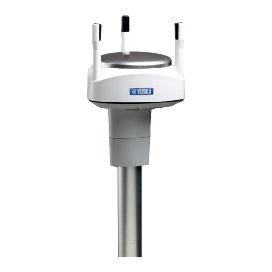
Chapter 2 __________________________________________________________ Product Overview CHAPTER 2 PRODUCT OVERVIEW This chapter introduces the unique features and advantages of the Vaisala Ultrasonic Wind Sensor WMT52. Introduction to Ultrasonic Wind Sensor WMT52 Figure 1 Ultrasonic Wind Sensor WMT52 0806-009 VAISALA _______________________________________________________________________ 15... -
Page 18: Heating Function
The heating function option must be chosen when placing the order. Optional Software for Easy Settings ® Windows based Vaisala Configuration Tool is a user friendly parameter setting software for WMT52. With this software tool you can ® change the device and sensor settings easily in Windows environment. -
Page 19: Ultrasonic Wind Sensor Wmt52 Components
Chapter 2 __________________________________________________________ Product Overview Ultrasonic Wind Sensor WMT52 Components Figure 2 WMT52 Components 0803-041 The following numbers refer to Figure 2 on page Top assembly Silicon gasket Spacers Bottom assembly Allen screws VAISALA _______________________________________________________________________ 17... -
Page 20: Figure 3 Bottom Of The Sensor
User’s Guide ______________________________________________________________________ Figure 3 Bottom of the Sensor 0803-029 The following numbers refer to Figure 3 on page Alignment direction sign 4-pin M8 connector for Service Port Water tight cable gland (optional, included in the Bushing and Grounding Kit) Opening for cable gland (if unused, cover with a hexagonal plug) 8-pin M12 connector for power/datacom cable (optional) -
Page 21: Figure 4 Mounting Kit (Optional)
USB RS-232/RS-485 cable with 8-pin M12 threaded connector (1.4 m) USB service cable with 4-pin M8 snap-on connector (1.4 m) The service cable, while connected between the service port and PC, forces the service port to RS-232 / 19200, 8, N, 1. VAISALA _______________________________________________________________________ 19... -
Page 22: Figure 6 Bird Spike Kit (Optional)
User’s Guide ______________________________________________________________________ Figure 6 Bird Spike Kit (optional) 0804-007 The optional Bird Spike Kit for WXT transmitters and WMT sensors is designed to reduce the interference that birds cause to the wind and rain measurement. The kit consists of a metallic band with spikes pointing upward. -
Page 23: Figure 7 Surge Protector (Optional)
Vaisala wind and weather instruments. The WSP150 should be installed close to the protected instrument (max 3 m). Vaisala Surge Protector WSP152 is designed to be used with Vaisala WXT transmitters and WMT sensors, to protect the host PC against surges entering through the USB port. - Page 24 User’s Guide ______________________________________________________________________ 22 ___________________________________________________________________M210925EN-B...
-
Page 25: Functional Description
This chapter describes the measurement principles and heating function of Ultrasonic Wind Sensor WMT52. Wind Measurement Principle The WMT52 uses Vaisala WINDCAP® sensor technology in wind measurement. The wind sensor has an array of three equally spaced ultrasonic transducers on a horizontal plane. Wind speed and wind directions are determined by measuring the time it takes the ultrasound to travel from each transducer to the other two. - Page 26 User’s Guide ______________________________________________________________________ The wind speed is calculated from the measured transit times using the following formula: – 0505-216 where: Wind speed Distance between the two transducers Transit time in forward direction Transit time in reverse direction Measuring the six transit times allows Vw to be computed for each of the three ultrasonic paths.
-
Page 27: Heating (Optional)
(Ta). Three fixed temperature limits, namely +10 °C, +4 °C, and -50 °C (+50 °F, +39 °F, -58 °F) control the heating as follows: Figure 8 Heating Control 0806-010 VAISALA _______________________________________________________________________ 25... - Page 28 User’s Guide ______________________________________________________________________ The following example shows how heating behaves as Ta starts to fall: When Ta falls below +10 °C, heating is enabled. Heating keeps Th > +4 °C until Ta < -11 °C. Between -11 ... -65 °C, Th is approximately 15 °C warmer than Ta.
-
Page 29: Chapter 4 Installation
Beware of damaging any of the wind transducers located at the top of the three antennas. Dropping the device can break or damage the transducers. If the antenna bends or twists the re-aligning can be difficult or impossible. VAISALA _______________________________________________________________________ 27... -
Page 30: Selecting The Location
User’s Guide ______________________________________________________________________ Selecting the Location Finding a suitable site for WMT52 is important for getting representative ambient measurements. The site should represent the general area of interest. The WMT52 should be installed in a location that is free from turbulence caused by nearby objects, such as trees and buildings. -
Page 31: Figure 10 Recommended Mast Length On Top Of A Building
Additional protection is needed in regions with frequent, severe thunderstorms, especially when long line cables (> 30m) are used. Vaisala recommends using a surge protectors such as the WSP150 and WSP152 in all sites where there is an elevated risk of lightning strike. -
Page 32: Installation Procedure
User’s Guide ______________________________________________________________________ Installation Procedure At the measurement site, WMT52 needs to be mounted, grounded, aligned, and connected to the data logger and the power source. Mounting Ultrasonic Wind Sensor WMT52 can be mounted either onto a vertical pole mast or onto a horizontal cross arm. When mounting WMT52 onto a pole mast, an optional mounting kit can be used to ease mounting. -
Page 33: Mounting With Optional Mounting Kit
Mount the adapter to the pole mast, do not tighten the fixing screw (provided). Align the sensor in such a way that the arrow points to north. Tighten the fixing screw ot the mounting adapter to fix the adapter firmly to the pole mast. VAISALA _______________________________________________________________________ 31... -
Page 34: Mounting To Horizontal Cross Arm
User’s Guide ______________________________________________________________________ Figure 12 Mounting WMT52 to Pole Mast Using Optional 0601-019 Mounting Kit The following numbers refer to Figure 12 on page Fixing screw Mounting kit NOTE When removing the WMT52 from the pole just turn the sensor so that it snaps out from the mounting kit. -
Page 35: Figure 13 Mounting Wmt52 To Cross Arm
The following numbers refer to : Nut (M6 DIN934) Mounting bolt (M6 DIN933) Figure 14 Mounting Bolt Location in Cross Arm 0803-042 The following numbers refer to Figure 14 on page Nut (M6 DIN934) Mounting Bolt (M6 DIN933) VAISALA _______________________________________________________________________ 33... -
Page 36: Grounding The Wmt52
Grounding using the Bushing and Grounding Kit If necessary, you can run a cable from the fixing screw to a grounding point. A Bushing and Grounding Kit (Vaisala order code: 222109) is available for this purpose. The kit includes a longer fixing screw, two nuts and washers, and an Abiko connector for the grounding cable. -
Page 37: Marine Grounding Jumper
Loosen the three allen screws at the bottom of WMT52. Pull out the bottom part of the sensor. Remove the grounding jumper from the PCB. Replace the bottom part and tighten the three screws. Do not overtighten. VAISALA _______________________________________________________________________ 35... -
Page 38: Aligning The Wmt52
User’s Guide ______________________________________________________________________ Aligning the WMT52 To help the alignment, there is an arrow and the text "North" on the bottom of the sensor. WMT52 needs to be aligned in such a way that this arrow points to the north. Wind direction can be referred either to true north, which uses the earth’s geographic meridians, or to the magnetic north, which is read with a magnetic compass. -
Page 39: Wind Direction Offset
Feed the deviation angle to the device by using the wind message formatting command aWU,D (direction offset), see section Checking the Settings (aWU) on page From now on, the WMT52 transmits the wind direction data by using the changed zero-alignment. Figure 18 Wind Direction Offset 0505-201 VAISALA _______________________________________________________________________ 37... - Page 40 User’s Guide ______________________________________________________________________ 38 ___________________________________________________________________M210925EN-B...
-
Page 41: Wiring And Power Management
40. The minimum consumption graph is for SDI-12 standby mode. The input power supply needs to be capable to deliver 60 mA (at 12 V) or 100 mA (at 6 V) instant current spikes with duration of 30 ms. These VAISALA _______________________________________________________________________ 39... -
Page 42: Heating Voltage
User’s Guide ______________________________________________________________________ are drawn by the wind sensor (whenever enabled) at 4 Hz rate, which is the default value for wind sampling. Wind sampling at 2 Hz or 1 Hz rate is also available (see Chapter 8, Sensor and Data Message Settings, on page 95). -
Page 43: Figure 20 Heating Current And Power Vs Vh
Heating Current and Power vs Vh 0805-22 CAUTION To avoid exceeding the maximum ratings in any condition, the voltages must be checked with no load at the power supply output. WARNING Make sure that you connect only de-energized wires. VAISALA _______________________________________________________________________ 41... -
Page 44: Wiring Using The 8-Pin M12 Connector
User’s Guide ______________________________________________________________________ Wiring Using the 8-pin M12 Connector External Wiring The 8-pin M12 connector (optional) is located on the bottom of the sensor, see Figure 3 on page 18. The pins of the 8-pin M12 connector as seen from outside the sensor are illustrated in the following figure. Figure 21 Pins of 8-pin M12 Connector 0308-032... -
Page 45: Internal Wiring
#19 VIN- will also do). For configuration work, the Service Port is most practical, since it has constant and convenient line parameters: RS232/19200, 8, N, 1. See Chapter 6, Connection Options, on page 51 Figure 3 on page VAISALA _______________________________________________________________________ 43... -
Page 46: Wiring Using The Screw Terminals
User’s Guide ______________________________________________________________________ Wiring Using the Screw Terminals Loosen the three screws at the bottom of the WMT52. Pull out the bottom part of the sensor. Insert the power supply wires and signal wires through the cable gland(s) in the bottom of the sensor. Cable glands are included in the optional Bushing and Grounding Kit (order code 222109). - Page 47 Short-circuit jumpers are required between pins 1-3 and 2-4 for the RS-485 communication mode. For the RS-422 mode, the jumpers need to be removed. In the other modes the jumpers may stay or they can be removed. VAISALA _______________________________________________________________________ 45...
-
Page 48: Data Communication Interfaces
User’s Guide ______________________________________________________________________ Data Communication Interfaces Figure 24 Data Communication Interfaces 0505-206 With RS-485 and RS-422 interfaces, termination resistors need to be used at both ends of the line, if data rate is 9600 Bd or higher and distance is 600 m (2000 ft) or longer. Resistor range 100 ... 180 suitable for twisted pair lines. -
Page 49: Power Management
Fully continuous wind measurement with 4 Hz sampling rate adds 2 ... 5 mA to the standby current (depending on the wind and some other climatic conditions). But for instance 10-second average requested every 2 minutes VAISALA _______________________________________________________________________ 47... - Page 50 User’s Guide ______________________________________________________________________ consumes 12 times less. And 1 Hz sampling rate makes it further decrease to one fourth. ASCII RS-232 Standby consumption with baud rates 4800 and higher is typically 0.24 mA. With a low baud rate selection (1200 or 2400 Bd) this is reduced to less than 0.19 mA.
- Page 51 When supplied through the Service port the minimum voltage level for reliable operation is 6V. This can also be seen in the supply voltage reading of the Supervisor message - the Vs value is 1V lower than the actual input voltage. VAISALA _______________________________________________________________________ 49...
- Page 52 User’s Guide ______________________________________________________________________ 50 ___________________________________________________________________M210925EN-B...
-
Page 53: Chapter 6 Connection Options
SDI-12 v1.3 and SDI-12 v1.3 continuous measurement You have chosen the communication protocol (ASCII, NMEA 0183 or SDI-12) when placing the order. In case you want to check and/or change the protocol or other communication settings, see the following sections. VAISALA _______________________________________________________________________ 51... -
Page 54: Connection Cables
Connector on Connector on Order Code Sensor End User End USB Service Cable (1.4m) M8 female USB type A 220614 (also includes Vaisala Configuration Tool software) USB Service Cable Adapter for WXT510/WMT50 M8 male 221523 WXT510/WMT50 service connector USB RS232/RS485 Cable... -
Page 55: Installing The Driver For The Usb Cable
COM port. There is no reason to uninstall the driver for normal use. However, if you wish to remove the driver files and all Vaisala USB cable devices, you can do so by uninstalling the entry for Vaisala USB Instrument Driver from the Add or Remove Programs (Programs and Features in Windows Vista) in the Windows Control Panel. -
Page 56: Service Cable Connection
The service cable connection is recommended for checking and changing the device settings. When making the changes, use the Vaisala Configuration Tool or a standard PC terminal program. The USB service cable is included in the Service Pack 2, see... -
Page 57: Connection Through M12 Bottom Connector Or Screw Terminal
Serial Interface Serial Settings SDI-12 1200 baud, 7, E, 1 RS-232, ASCII 19200 baud, 8, N, 1 RS-485, ASCII 19200 baud, 8, N, 1 RS-422 ASCII 19200 baud, 8, N, 1 RS-422 NMEA 4800 baud, 8, N, 1 VAISALA _______________________________________________________________________ 55... -
Page 58: Communication Setting Commands
See section Supervisor Message on page 101. The information field is set as part of the factory settings (see General Unit Settings on page 138). You can only modify it using the Vaisala Configuration Tool. 56 ___________________________________________________________________M210925EN-B... -
Page 59: Setting Fields
Effective in ASCII, polled and NMEA 0183 query protocols. Effective when RS-485 is selected (C = 3). Name of the device: WMT52 (read only) Software version: for example, 1.00 (read only) <cr><lf> Response terminator VAISALA _______________________________________________________________________ 57... - Page 60 User’s Guide ______________________________________________________________________ NOTE There are two different SDI-12 modes available for providing all the functionality of the SDI-12 v1.3 standard. The lowest power consumption is achieved with the Native SDI-12 mode (aXU,M=S), as it makes measurements and outputs data only on request.
-
Page 61: Changing The Communication Settings (Axu)
1200, 7, E, 1 and the communication protocol to SDI-12 (M=S). NOTE Reset the sensor to validate the changes of communication parameters by disconnecting the service cable or using the Reset (aXZ) command, see Reset (aXZ) on page VAISALA _______________________________________________________________________ 59... - Page 62 User’s Guide ______________________________________________________________________ Example (ASCII and NMEA 0183, device address 0): Changing the device address from 0 to 1: 0XU,A=1<cr><lf> 1XU,A=1<cr><lf> Checking the changed settings: 1XU<cr><lf> 1XU,A=1,M=P,T=1,C=2,B=19200,D=8,P=N,S=1,L=25, N=WMT50,V=1.00<cr><lf> Example (ASCII, device address 0): Changing RS-232 serial interface with ASCII, polled communication protocol and baud settings 19200, 8, N, 1 to RS-485 serial interface with ASCII, automatic protocol and baud settings 9600, 8, N, 1.
-
Page 63: Getting The Data Messages
The parameters are in the same order as in the Setting Field tables in chapter Sensor and Data Message Settings on page 95. The order of the parameters is fixed, but you can exclude any parameter from the list when configuring the sensor. VAISALA _______________________________________________________________________ 61... -
Page 64: General Commands
User’s Guide ______________________________________________________________________ General Commands In case the error messaging is disabled (see Supervisor Message on page 101), WMT52 does not return any response message with the general commands given in ASCII and NMEA-formats. Reset (aXZ) This command is used to perform software reset on the device. Command format in ASCII and NMEA 0183: aXZ<cr><lf>... -
Page 65: Measurement Reset (Axzm)
Command format in SDI-12: aXZM! where Device address Measurement break command <cr><lf> Command terminator in ASCII and NMEA 0183 Command terminator in SDI-12 Example (ASCII): 0XZM<cr><lf> 0TX,Measurement reset<cr><lf> Example (SDI-12): 0XZM!0 (= device address) Example (NMEA 0183): 0XZM<cr><lf> $WITXT,01,01,09,Measurement reset*50<cr><lf> VAISALA _______________________________________________________________________ 63... -
Page 66: Ascii Protocol
User’s Guide ______________________________________________________________________ ASCII Protocol This section presents the data commands and data message formats for the ASCII communication protocols. Abbreviations and Units For changing the units, see Chapter 8, Sensor and Data Message Settings, on page Table 6 Abbreviations and Units Abbreviation Name Unit... -
Page 67: Acknowledge Active Command (A)
This command is used to ensure that a device is responding to a data recorder or another device. It asks a device to acknowledge its presence on the bus. Command format: a<cr><lf> where Device address <cr><lf> Command terminator The response: a<cr><lf> where Device address <cr><lf> Response terminator Example: 0<cr><lf> 0<cr><lf> VAISALA _______________________________________________________________________ 65... -
Page 68: Wind Data Message (Ar1)
User’s Guide ______________________________________________________________________ Wind Data Message (aR1) With this command you can request the wind data message. Command format: aR1<cr><lf> where Device address Wind message query command <cr><lf> Command terminator Example of the response (the parameter set is configurable): 0R1,Dn=236D,Dm=283D,Dx=031D,Sn=0.0M,Sm=1.0M, Sx=2.2M<cr><lf>... -
Page 69: Supervisor Data Message (Ar5)
101. The content of the parameter "Id" is a text string which can be modified by using the Vaisala Configuration Tool only. Field can include customer-specific, additional information. For more information on changing the settings, refer to the Vaisala Configuration Tool on-line help for the Info field in the Device Settings window. -
Page 70: Combined Data Message (Ar)
User’s Guide ______________________________________________________________________ Combined Data Message (aR) With this command you can request all individual messages aR1 and aR5 with just one command. Command format: aR<cr><lf> where Device address (default = 0) Combined message query command <cr><lf> Command terminator Example of the response: 0R1,Dm=027D,Sm=0.1M<cr><lf>... -
Page 71: Polling With Crc
The correct CRC for each command can be requested by typing the command with an arbitrary three-character CRC. Example of asking the CRC for the wind data message query ar1: Command format: ar1yyy<cr><lf> where Device address Wind message query command Arbitrary three-character CRC <cr><lf> Command terminator VAISALA _______________________________________________________________________ 69... -
Page 72: Automatic Mode
User’s Guide ______________________________________________________________________ Response: atX,Use chksum GoeIU~<cr><lf> where Device address tX,Use Text prompt chksum Correct three-character CRC for the ar1 command Three-character CRC for the response message <cr><lf> Response terminator Example of the other data query commands with CRC (when the device address is 0): Supervisor query 0r5Kcd<cr><lf>... -
Page 73: Automatic Composite Data Message (Ar0)
In this mode all the commands presented in this chapter are available except those for the Continuous Measurement.In SDI-12 v1.3 continuous mode (aXU,M=R) the sensor makes internal measurements at update intervals configurable by the user, see Chapter VAISALA _______________________________________________________________________ 71... -
Page 74: Address Query Command (?)
User’s Guide ______________________________________________________________________ 8, Sensor and Data Message Settings, on page 95. The data is outputted when requested. In this mode all the commands presented in this chapter are available. For changing the message parameters, units and other settings, see Chapter 8, Sensor and Data Message Settings, on page In the Native SDI-12 mode (aXU,M=S) the WMT52 is in idle state most of the time (power consumption <... -
Page 75: Acknowledge Active Command (A)
Command format: aAb! where Device address Change address command Address to change to Command terminator VAISALA _______________________________________________________________________ 73... -
Page 76: Send Identification Command (Ai)
User’s Guide ______________________________________________________________________ The response: b<cr><lf> where Device address = the new address (or the original address, if the device is unable to change it) <cr><lf> Response terminator Example (changing address from 0 to 3): 0A3!3<cr><lf> Send Identification Command (aI) This command is used to query the device for the SDI-12 compatibility level, model number, and firmware version and serial number. -
Page 77: Start Measurement Command (Am)
Commands on page Command terminator The response is sent in two parts. The response part one: atttn<cr><lf> The response part two (indicates that the data is ready to be requested): a<cr><lf> where Device address VAISALA _______________________________________________________________________ 75... -
Page 78: Start Measurement Command With Crc (Amc)
User’s Guide ______________________________________________________________________ The measurement completing time in seconds The number of the measured parameters available (maximum number is 9) <cr><lf> Response terminator NOTE For changing the message parameters, units and other settings, see Chapter 8, Sensor and Data Message Settings, on page NOTE When the measurement takes less than one second, the response part two is not sent. -
Page 79: Start Concurrent Measurement With Crc (Acc)
The number of the measured parameters available (maximum number is 20) <cr><lf> Response terminator NOTE For changing the message parameters, units and other settings, see Chapter 8, Sensor and Data Message Settings, on page Start Concurrent Measurement with CRC (aCC) Command format: aCCx! VAISALA _______________________________________________________________________ 77... -
Page 80: Send Data Command (Ad)
User’s Guide ______________________________________________________________________ This command has the same function as aC but a three-character CRC is added to the response data strings before <cr><lf>. In order to request the measured data, Send data command aD should be used, see the following sections. Send Data Command (aD) This command is used to request the measured data from the device. -
Page 81: Examples Of Am, Ac And Ad Commands
The device address is 0 in all examples. Example 1: Start a wind measurement and request the data (all six wind parameters are enabled in the message): 0M1!00036<cr><lf> (measurement ready in 3 seconds and 6 parameters available) 0<cr><lf> (measurement completed) 0D0!0+339+018+030+0.1+0.1+0.1<cr><lf> VAISALA _______________________________________________________________________ 79... -
Page 82: Continuous Measurement (Ar)
User’s Guide ______________________________________________________________________ Example 2: Start a supervisor measurement with CRC and request the data: 0MC5!00014<cr><lf> (measurement ready in one second and 4 parameters available) 0<cr><lf> (measurement completed) 0D0!0+34.3+10.5+10.7+3.366DpD<cr><lf> Continuous Measurement (aR) The device can be configured so that all the parameters can be requested instantly with the command aR instead of the two phase request procedure of commands aM, aMC, aC, aCC + aD. -
Page 83: Continuous Measurement With Crc (Arc)
Example (device address 0): 0RC3!0+0.04+10+14.8+0.0+0+0.0INy Start Verification Command (aV) This command is used to query self diagnostic data from the device. However, the command is not implemented in WMT52. The self- diagnostic data can be requested with aM5 command. VAISALA _______________________________________________________________________ 81... -
Page 84: Nmea 0183 V3.0 Protocol
User’s Guide ______________________________________________________________________ NMEA 0183 V3.0 Protocol This section presents the data query commands and data message formats for the NMEA 0183 v3.0 query and automatic protocols. For changing the message parameters, units and other settings, see Chapter 8, Sensor and Data Message Settings, on page A two-character checksum (CRC) field is transmitted in all data request sentences. -
Page 85: Acknowledge Active Command (A)
W (see section Wind Sensor on page 95). With MWV query only wind speed and direction average values can be requested. For obtaining min and max data for speed and direction, see section XDR Transducer Measurement Query on page VAISALA _______________________________________________________________________ 83... - Page 86 User’s Guide ______________________________________________________________________ Command format: $--WIQ,MWV*hh<cr><lf> where Start of the message Device identifier of the requester Device type identifier (WI = weather instrument) Defines the message as Query Wind speed and direction query command Checksum delimiter Two-character checksum for the query command. <cr><lf>...
-
Page 87: Xdr Transducer Measurement Query
Defines the message as Query Transducer measurement command Checksum delimiter Two-character checksum for the query command. <cr><lf> Command terminator The response includes the parameters activated in the data messages (see Chapter 8, Sensor and Data Message Settings, on page 95). VAISALA _______________________________________________________________________ 85... - Page 88 User’s Guide ______________________________________________________________________ NOTE The parameter order in the output is as shown in the parameter selection setting field, see Chapter 8, sections Setting the Fields. The response format: $WIXDR,a1,x.x1,u1,c--c1, ..an,x.xn,un,c--cn*hh<cr><lf> where Start of the message Device type identifier (WI = weather instrument) Transducer measurement response identifier Transducer type for the first transducer, see the following transducer table.
-
Page 89: Table 7 Transducer Ids Of The Measurement Parameters
Example of the XDR Query (all parameters of each sensor enabled and NMEA wind formatter set to T): $--WIQ,XDR*2D<cr><lf> Example of the response when all the parameters of each sensor are enabled (NMEA wind formatter set to T): VAISALA _______________________________________________________________________ 87... - Page 90 User’s Guide ______________________________________________________________________ Wind sensor data $WIXDR,A,302,D,0,A,320,D,1,A,330,D,2,S,0.1,M,0,S,0.2,M,1,S,0.2, M,2*57<cr><lf> Supervisor data $WIXDR,C,20.4,C,2,U,12.0,N,0,U,12.5,V,1,U,3.460,V,2,G,HEL/ ___,,4*2D 88 ___________________________________________________________________M210925EN-B...
- Page 91 Transducer id 2 type (wind speed) Transducer id 2 data (max wind speed) Transducer id 2 units (m/s, max wind speed) Transducer id for max wind speed Checksum delimiter Two-character checksum for the response <cr><lf> Response terminator VAISALA _______________________________________________________________________ 89...
- Page 92 User’s Guide ______________________________________________________________________ The structure of the supervisor response message: where Start of the message Device type (WI = weather instrument) Transducer measurement response identifier Transducer id 2 type (temperature), see the following Transducer table 20.4 Transducer id 2 data (Heating temperature) Transducer id 2 units (C, Heating temperature) Transducer id for Heating temperature Transducer id 0 type (voltage)
-
Page 93: Txt Text Transmission
Talker identifier (WI = weather instrument) Text transmission identifier. Total number of messages, 01 to 99 Message number. Text identifier (see text message table) c---c Text message (see text message table) Checksum delimiter Two-character checksum for the query command. <cr><lf> Response terminator VAISALA _______________________________________________________________________ 91... -
Page 94: Automatic Mode
User’s Guide ______________________________________________________________________ Examples: $WItXT,01,01,01,Unable to measure error*6D<cr><lf> (wind data request when all the wind parameters were disabled from the wind message). $WITXT,01,01,03,Unknown cmd error*1F (unknown command 0XO!<cr><lf>). $WITXT,01,01,08,Use chksum 2F*72 (wrong checksum used in MWV query command) Automatic Mode When NMEA 0183 v3.0 automatic protocol is selected, the sensor sends data messages at user configurable update intervals. -
Page 95: Automatic Composite Data Message (Ar0)
For selecting the parameter set in the response message, see Chapter 8, Sensor and Data Message Settings, on page Automatic composite data messaging is a concurrent, not an alternate mode to either the polled or automatic modes. VAISALA _______________________________________________________________________ 93... - Page 96 User’s Guide ______________________________________________________________________ 94 ___________________________________________________________________M210925EN-B...
-
Page 97: Sensor And Data Message Settings
ASCII, NMEA 0183 and SDI-12. Sensor and data message settings can also be done by using the Vaisala Configuration Tool software.With this software tool you can change the device and sensor settings easily in Windows® environment. See... - Page 98 User’s Guide ______________________________________________________________________ Command format in ASCII and NMEA 0183: aWU<cr><lf> Command format in SDI-12: aXWU! where Device address Wind sensor settings command in ASCII and NMEA 0183 Wind sensor settings command in SDI-12 <cr><lf> Command terminator in ASCII and NMEA 0183 Command terminator in SDI-12 The response in ASCII and NMEA 0183: aWU,R=[R],I=[I],A=[A],G=[G,U=[U],D=[D],N=[N],F=[F]<cr><...
-
Page 99: Setting Fields
Defines the period over which the wind speed and direction averaging is calculated. Same period is also used for maximum and minimum calculation. See also Appendix D Wind Measurement Averaging Method on page 135 for difference in averaging practices when A<I and A>I. VAISALA _______________________________________________________________________ 97... - Page 100 User’s Guide ______________________________________________________________________ Wind speed max/min calculation mode: 1 or 3 seconds G =1: Traditional max/min calculation is performed both for speed and direction. G =3: Gust & lull are calculated for wind speed, while direction calculation is as it is with G =1. the output messages, gust &...
-
Page 101: Changing The Settings (Awu)
NOTE If averaging time [A] is greater than update interval [I], it shall be a whole multiple of the update interval and at maximum 12 times greater. Example: If I = 5 s, A = 60 s. VAISALA _______________________________________________________________________ 99... - Page 102 User’s Guide ______________________________________________________________________ Examples (ASCII and NMEA 0183, device address 0): You need a 20-second averaging time for wind speed and direction both in wind data and composite data message in every 60 seconds. Wind speed shall be in knots and wind direction offset +10°. Changing the measurement interval to 60 seconds: 0WU,I=60<cr><lf>...
-
Page 103: Supervisor Message
Supervisor settings command in ASCII and NMEA 0183 Supervisor settings command in SDI-12 <cr><lf> Command terminator in ASCII and NMEA 0183 Command terminator in SDI-12 The response in ASCII and NMEA 0183: aSU,R=[R],I=[I],S=[S],H=[Y]<cr><lf> The response in SDI-12: aXSU,R=[R],I=[I],S=[S],H=[Y]<cr><lf> VAISALA ______________________________________________________________________ 101... -
Page 104: Setting Fields
User’s Guide ______________________________________________________________________ Setting Fields Parameter selection: This field consists of 16 bits defining the supervisor parameters included in the data messages. The bit value 0 disables and the bit value 1 enables the parameter. The bits 1-8 determine the 1st bit (most left) Th Heating temperature parameters included in the... -
Page 105: Changing The Settings (Asu)
Command format in SDI-12; aXSU,R=x,S=x,H=x! where R, I, S, H The supervisor setting fields, see Setting Fields on page 102. Value for the setting <cr><lf> Command terminator in ASCII and NMEA 0183 Command terminator in SDI-12 VAISALA ______________________________________________________________________ 103... -
Page 106: Composite Data Message (Ar0)
User’s Guide ______________________________________________________________________ Example (ASCII and NMEA 0183, device address 0): Disabling the heating and error messaging: 0SU,S=N,H=N<cr><lf> 0SU,S=N,H=N<cr><lf> Example (SDI-12, device address 0): Changing the update interval to 10 seconds: 0XSU,I=10!0<cr><lf> In SDI-12 mode a separate enquiry (0XSU!) must be given to check the data content. - Page 107 (Dm) and average wind speed (Sm): 0WU,R=&01001000<cr><lf> 0WU,R=11110000&01001000<cr><lf> Remove the heating temperature (Th) data from the composite data message, and include the information field (Id): 0SU,R=&00001000<cr><lf> 0SU,R=11110000&00001000<cr><lf> The final composite data message query and response in ASCII: 0R0<cr><lf> 0R0,Dm=009D,Sm=0.2M,Id=HEL___<cr><lf> VAISALA ______________________________________________________________________ 105...
- Page 108 User’s Guide ______________________________________________________________________ 106 __________________________________________________________________M210925EN-B...
-
Page 109: Chapter 9 Maintenance
Chapter 9 ______________________________________________________________ Maintenance CHAPTER 9 MAINTENANCE This chapter contains instructions for the basic maintenance of Ultrasonic Wind Sensor WMT52 and contact information for Vaisala Service Centers. Cleaning To ensure the accuracy of measurement results, Ultrasonic Wind Sensor WMT52 needs to be cleaned when it gets contaminated. Leaves and... -
Page 110: Factory Calibration And Repair Service
Phone: +81 3 3266 9617, Fax: +81 3 3266 9655 E-mail: aftersales.asia@vaisala.com BEIJING SERVICE CENTER Vaisala China Ltd., Floor 2 EAS Building, No. 21 Xiao Yun Road, Dongsanhuan Beilu, Chaoyang District, Beijing, P.R. CHINA 100027. Phone: +86 10 8526 1199, Fax: +86 10 8526 1155 E-mail: china.service@vaisala.com... -
Page 111: Chapter 10 Troubleshooting
In ASCII and NMEA protocols both <cr> and <lf> are required after each command. Check that your terminal program sends both when pressing enter. Note: The direction unit is # for the wind speeds less than 0.05 m/s. VAISALA ______________________________________________________________________ 109... -
Page 112: Table 10 Communication Problems
A command mistyped in ASCII/ Getting the Data Messages, on NMEA mode while error page messaging/text messages is Enable the error messaging disabled (aSU,S=N). using the Vaisala Configuration Tool or any terminal by setting aSU,S=Y, then try the command again. 110 __________________________________________________________________M210925EN-B... -
Page 113: Self-Diagnostics
The communication protocol Check the communication expected format. may not be the one you want. protocol of the device by using the Vaisala Configuration Tool or any terminal with command aXU,M! (SDI-12) aXU,M<cr><lf> (ASCII/NMEA) and change it if needed. See... -
Page 114: Table 11 Error Messaging/Text Messages Table
See also Chapter 10, Troubleshooting, on page 109. In case of constant error, please contact Vaisala Service Center, see Vaisala Service Centers on page 108. NOTE When WMT52 is used on an RS-485 bus with other polled devices, the error messaging feature shall always be disabled. -
Page 115: Wind Sensor Heating Control
(Vs). In case of deviations between the supplied voltage and monitored voltage, check the wiring and the power supply. Technical Support For technical questions, contact the Vaisala technical support: E-mail helpdesk@vaisala.com +358 9 8949 2790... - Page 116 User’s Guide ______________________________________________________________________ 114 __________________________________________________________________M210925EN-B...
-
Page 117: Technical Specifications
1 ... 3600 s (= 60 min), at 1 s steps, on the basis of samples taken at 4, 2 or 1 Hz rate (configurable) update interval 1 ... 3600 s (= 60 min), at 1 s steps VAISALA ______________________________________________________________________ 115... -
Page 118: Table 13 Inputs And Outputs
User’s Guide ______________________________________________________________________ Table 13 Inputs and Outputs Property Description/Value Operation voltage 5 ... 32 VDC Average current consumption minimum 0.1 mA @ 12 VDC (SDI-12 standby) typical 3 mA @ 12 VDC (with default measuring interval) maximum 14 mA @ 5 VDC (with constant measurement with shortest measuring interval) Heating voltage... -
Page 119: Table 15 Electromagnetic Compatibility
Polycarbonate + 20% glass fibre Weight WMT52 510 g with mounting adapter 595 g Table 17 General Property Description/Value Self-diagnostic Separate supervisor message, unit/status fields to validate measurement stability Start-up Automatic, <5 seconds from power on to the first valid output VAISALA ______________________________________________________________________ 117... -
Page 120: Options And Accessories
User’s Guide ______________________________________________________________________ Options and Accessories Table 18 Options and Accessories Description Order code Service Pack 2: Vaisala Configuration Tool 220614 software and USB service cable USB service cable adapter for WXT510/ 221523 WMT50 2-meter cable with 8-pin M12 female... -
Page 121: Dimensions
Chapter 11 ____________________________________________________ Technical Specifications Dimensions Figure 25 WMT52 Dimensions in mm (inch) 0803-045 VAISALA ______________________________________________________________________ 119... -
Page 122: Figure 26 Mounting Kit Dimensions In Mm (Inch)
User’s Guide ______________________________________________________________________ Figure 26 Mounting Kit Dimensions in mm (inch) 0505-211 The following numbers refer to Figure 19 on page 94: Mounting kit with adapter sleeve for ø26.7 mm mast tube Mounting kit without adapter sleeve for ø30 mm mast tube 120 __________________________________________________________________M210925EN-B... -
Page 123: Appendix Anetworking
In the data logger end, combine the "GND for data" wires of each WMT52 to the logger "GND for data" wire. Connect the "Data in/ out" wires of each WMT52 to the logger "Data" wire. VAISALA ______________________________________________________________________ 121... -
Page 124: Communication Protocol
User’s Guide ______________________________________________________________________ Communication Protocol Set the communication protocol SDI-12 v 1.3 (aXU,C=1,M=S) or SDI- 12 v1.3 continuous (aXU,C=1,M=R). WMT52s on the bus shall be assigned with different addresses (for example: aXU,A=0,1,2, ... ). Thereafter WMT52s on the bus do not respond to the commands not assigned to them nor to the data messages sent by the other WMT52s. -
Page 125: Communication Protocol
Example (a bus with three WMT52s): WMT52 #1 communication settings: 0XU,A=0,M=P,C=3,I=0,B=19200,D=8,P=N,S=1,L=25 WMT52 #2 communication settings: 1XU,A=1,M=P,C=3,I=0,B=19200,D=8,P=N,S=1,L=25 WMT52 #3 communication settings: 2XU,A=2,M=P,C=3,I=0,B=19200,D=8,P=N,S=1,L=25 Example (composite data message queries to the sensors 1 and 3 are assigned as follows): 0R0<cr><lf> 1R0<cr><lf> 2R0<cr><lf> VAISALA ______________________________________________________________________ 123... -
Page 126: Nmea 0183 V3.0, Query
User’s Guide ______________________________________________________________________ NMEA 0183 v3.0, Query The NMEA 0183 query messages do not contain device address information. Individual query commands can thus not be directed to different devices. Instead, a specific Time Slot method can be used for receiving data from several devices on the bus, just with a single query command. - Page 127 NMEA XDR messages can only be numbers. The addresses given in letters will show in the transducer IDs in the following way: WMT52 address = A => transducer ID = 10, B => 11, a => 36, b => 37 etc. VAISALA ______________________________________________________________________ 125...
-
Page 128: Nmea 0183 V3.0 Query With Ascii Query Commands
User’s Guide ______________________________________________________________________ NMEA 0183 v3.0 Query with ASCII Query Commands You can use ASCII query commands aR1, aR5, aR, aR0 and their CRC-versions ar1, ar5, ar and ar0 also in NMEA 0183 protocol. The responses to these commands will be in standard NMEA 0183 format. and the sensors shall be assigned with different addresses (for example: aXU,A=0,1,2, ... - Page 129 The query for WMT52 #3 and the response: 2R<cr><lf> $WIXDR,A,341,D,2,A,347,D,3,A,357,D,4,S,0.1,M,2,S,0.2,M,3,S,0.2, M,4*53<cr><lf> $WIXDR,C,23.5,C,2,C,24.3,C,3,H,49.3,P,2,P,1010.1,H, 2*5F<cr><lf> $WIXDR,V,0.000,I,2,Z,0,s,2,R,0.00,I,2,V,0.0,M,3,Z,0,s,3,R,0.0,M, 3*61<cr><lf> $WIXDR,C,25.8,C,4,U,10.6,N,2,U,10.9,V,2,U,3.360,V,3*7C<cr><lf> If needed, for making the transducers IDs distinguishable, device addresses 0, 4, 8 can be used as described in the previous section. VAISALA ______________________________________________________________________ 127...
- Page 130 User’s Guide ______________________________________________________________________ 128 __________________________________________________________________M210925EN-B...
-
Page 131: Sdi-12 Protocol
12-volt line. The SDI-12 bus can have at least 10 sensors connected to it. The bus topology is a parallel connection, where each of the three wires of different sensors are connected in parallel. VAISALA ______________________________________________________________________ 129... -
Page 132: Sdi-12 Communications Protocol
User’s Guide ______________________________________________________________________ SDI-12 Communications Protocol SDI-12 data recorders and sensors communicate by an exchange of ASCII characters on the data line. The data recorder sends a break to wake up the sensors on the data line. A break is continuous spacing on the data line for at least 12 milliseconds. -
Page 133: Sdi-12 Timing
100 milliseconds after detecting a break. After a data recorder transmits the last character of a command, it must relinquish control of the data line within 7.5 milliseconds. Figure 27 SDI-12 Timing Diagram 0505-218 VAISALA ______________________________________________________________________ 131... - Page 134 User’s Guide ______________________________________________________________________ After receiving the break and the command, the addressed sensor sets the data line to marking at 8.33 milliseconds and then sends the response (tolerance: -0.40 milliseconds.) The start bit of the first response byte must start within 15 milliseconds after the stop bit of the last byte of the command (tolerance: +0.40 milliseconds).
-
Page 135: Crc-16 Computation
=1 to 8 if the least significant bit of the CRC is one right shift the CRC one bit set CRC equal to the exclusive OR of 0xA001 and itself else right shift the CRC one bit VAISALA ______________________________________________________________________ 133... -
Page 136: Encoding The Crc As Ascii Characters
User’s Guide ______________________________________________________________________ Encoding the CRC as ASCII Characters The 16 bit CRC is encoded to three ASCII characters by using the following algorithm: 1st character = 0x40 OR (CRC shifted right 12 bits) 2nd character = 0x40 OR ((CRC shifted right 6 bits) AND 0x3F) 3rd character = 0x40 OR (CRC AND 0x3F) The three ASCII characters are placed between the data and <cr><lf>. -
Page 137: Wind Measurement Averaging Method
Wind measurement sampling rate (4, 2, or 1 Hz) does not have any effect on the averaging scheme. It determines from how many samples the one second values seen in the figures are calculated. VAISALA ______________________________________________________________________ 135... -
Page 138: Figure 28 Wind Measurement Averaging Method
User’s Guide ______________________________________________________________________ Case 1 I > A, all comm unication p rotocols other than SDI-12 (aXU,M=S). In this example I=5 sec and A=3 sec. time 1 sec Case 2 I < A, all comm unication p rotocols other than SDI-12 (aXU,M=S). In this example I=2 sec and A=5 sec. time 1 sec Case 3... -
Page 139: Factory Configurations
The factory configurations are read-only settings which cannot be modified. For each settings command, the following information is shown: the command to retrieve the settings (ends with ! character) an example response from the WMT a table describing the messsage contents VAISALA ______________________________________________________________________ 137... -
Page 140: General Unit Settings
User’s Guide ______________________________________________________________________ General Unit Settings 0XF!0XF,f=11111111&11100010,o=AAC1DB1A,c=A263, i=HEL___,n=A3430012,2=2528,3=3512 <cr><lf> Table 19 General Unit Settings Field Character Field Name Description Factory options Selection of parameters Order code Ordering identity as delivered (10 characters) Calibration date Y=2003, A, B,…=2005, 2006, 1..52 = week, 1...7, weekday Info Factory signature (10 characters) -
Page 141: Supervisor Settings
Direct ADC value of temp.diode 0...4096 Defrosting limit w. 50% duty -100.0 ...[m] °C (default -4.0 °C) cycle Heating limit w. full power [l]...[h] °C(default 0.0 °C) Heating limit w. 50% duty cycle [m]...100.0 °C (default 4.0 °C) VAISALA ______________________________________________________________________ 139... - Page 142 User’s Guide ______________________________________________________________________ 140 __________________________________________________________________M210925EN-B...
- Page 143 *M210925EN*...
Need help?
Do you have a question about the WINDCAP WMT52 and is the answer not in the manual?
Questions and answers