Table of Contents
Advertisement
Advertisement
Table of Contents

Related Manuals for Vaisala LM21


Summary of Contents for Vaisala LM21
- Page 1 Background Luminance Sensor LM21 UIDE M210283en-A September 2002...
- Page 2 Finland Visit our Internet pages at http://www.vaisala.com/ © Vaisala 2002 No part of this manual may be reproduced in any form or by any means, electronic or mechanical (including photocopying), nor may its contents be communicated to a third party without prior written permission of the copyright holder.
-
Page 3: Table Of Contents
Concept of Runway Background Illumination..14 Product Nomenclature .........16 CHAPTER 3 INSTALLATION ..............17 General Installation and Alignment.....17 Installation to FS11 Visibility Sensor ....18 Startup Tests for LM21 with FS11 ......23 CHAPTER 4 OPERATION ................25 Operation with FS11 ..........25 Default Factory Settings ........26 CHAPTER 5 THEORY OF OPERATION............27... - Page 4 Specifications ............57 Mechanical Specifications........57 Operational Specifications ......... 58 Optical Specifications......... 58 Electrical Specifications ........58 Environmental Specifications ......59 Electromagnetic Compatibility ......59 INDEX ..................61 List of Figures Figure 1 LM21 Background Luminance Sensor ....14 4 ______________________________________________________ M210283en-A...
- Page 5 ___________________________________________________________________ Figure 2 Mounting LM21 on the Option Support Arm of FS1118 Figure 3 Installation and Cabling of LM21......20 Figure 4 Wiring of LM21 to FS11 ..........21 Figure 5 Cable Grounding Instruction ........22 Figure 6 Exploded View of LM21 Background Luminance Sensor ..............28...
- Page 6 User's Guide ________________________________________________________ This page intentionally left blank. 6 ______________________________________________________ M210283en-A...
-
Page 7: Chapter 1 General Information
- Chapter 4, Operation, contains information that is needed to operate LM21 when it is installed to an FS11 Visibility Sensor system. - Chapter 5, Theory of Operation, describes the theory of operation of LM21 Background Luminance Sensor. -
Page 8: Version Information
Table 1 Manual Revisions Manual Code Description M210283en-A First release of the LM21 User's Guide (this manual) Related Manuals The need for the following manuals, which are for related sensors, computers, displays, and such equipment, depends on the system configuration. (These documents are not included in the standard LM21 delivery.) -
Page 9: Safety
Note highlights important information on using the product. NOTE Product Related Safety Precautions The LM21 Background Luminance Sensor delivered to you has been tested for safety and approved as shipped from the factory. VAISALA___________________________________________________________9... - Page 10 Failure to comply with these precautions or with specific warnings elsewhere in this manual violates safety standards of design, manufacture, and intended use of the equipment. Vaisala and its subsidiaries assume no liability for the customer's failure to comply with these requirements. Note the following precautions:...
-
Page 11: Esd Protection
ESD Protection Electrostatic Discharge (ESD) can cause immediate or latent damage to electronic circuits. Vaisala products are adequately protected against ESD for their intended use. However, it is possible to damage the product by delivering electrostatic discharges when touching, removing, or inserting any objects inside the equipment housing. -
Page 12: Warranty
User's Guide ________________________________________________________ Warranty For certain products Vaisala normally gives a limited one year warranty. Please observe that any such warranty may not be valid in case of damage due to normal wear and tear, exceptional operating conditions, negligent handling or installation, or unauthorized modifications. -
Page 13: Chapter 2 Product Overview
RVR assessment equipment provided by Vaisala. The background luminance has an effect on the distinctiveness of the runway lights as seen by a pilot. LM21 measures the total amount of light coming in from an angle of 6 degrees and sends the measurement results to the interface unit of FS11 Visibility Sensor via an RS-485 connection. -
Page 14: Concept Of Runway Background Illumination
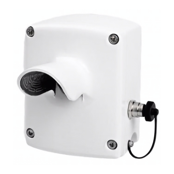
User's Guide ________________________________________________________ 0205-012 Figure 1 LM21 Background Luminance Sensor Concept of Runway Background Illumination In order for the runway lights to be seen, they have to illuminate the eye to a level above the threshold for detection. In RVR (runway visual range) calculations, the visual threshold of illumination is called the ET. -
Page 15: Table 4 Background Luminance Values In Relation To The
8 x 10 - Intermediate 51 - 999 8 x 10 - Normal day 1000 - 12 000 8 x 10 - Bright day (sun, More than 12 000 fog) LM21 Background Luminance Sensor supplies continuous background luminance values for RVR calculations. VAISALA__________________________________________________________15... -
Page 16: Product Nomenclature
LMB201 Luminance Detector board Measurement Board LM21FD Background For background luminance Luminance Sensor measurement in FD12P systems LM21MITRAS Background For background luminance Luminance Sensor measurement in MITRAS systems LMA21 LM21 Field Device for LM21 field Calibrator calibration 16 _____________________________________________________ M210283en-A... -
Page 17: Chapter 3 Installation
20 to 50 degrees referred to horizontal level. A good practice to choose the tilt angle is to direct the sensor slightly above the runway lights. The LM21 sensor is designed for measuring the background, against which pilots view the runway lights or the runway markings. -
Page 18: Installation To Fs11 Visibility Sensor
Mounting LM21 on the Option Support Arm of FS11 Installation to FS11 Visibility Sensor The LM21 sensor is mounted on the FS11 Option Support Arm, which is attached to the rear panel of the interface unit radiation shield. The mechanical installation of LM21 on the Option Support Arm including the cabling are shown in Figure 3 on page 20. - Page 19 The cable shield of the Background Luminance Sensor cable must be properly grounded into the cable gland, see Figure 5 on page 22. Adjust the viewing angle of the LM21 sensor to be close to 30° if there is no special reason to use another angle.
-
Page 20: Figure 3 Installation And Cabling Of Lm21
User's Guide ________________________________________________________ 0205-014 Figure 3 Installation and Cabling of LM21 The following letters refer to Figure 3 above: 1 = FS11 Option Support Arm 2 = Cable feedthrough hole 3 = Optional Cable feedthrough hole for opposite viewing direction... -
Page 21: Figure 4 Wiring Of Lm21 To Fs11
Chapter 3 __________________________________________________ Installation 0205-015 Figure 4 Wiring of LM21 to FS11 VAISALA__________________________________________________________21... -
Page 22: Figure 5 Cable Grounding Instruction
OPEN command to open the maintenance line. Give the configuration command SET BL_SENSOR LM21 to add the LM21 sensor output into the FS11 system and the data messages. With this command, the interface unit CPU starts polling the LM21 sensor via the internal RS-485 sensor interface. -
Page 23: Startup Tests For Lm21 With Fs11
Chapter 3 __________________________________________________ Installation Startup Tests for LM21 with FS11 To test the operation of LM21 Background Luminance Sensor, open the maintenance line with the OPEN command using a maintenance terminal connected to the FS11 interface enclosure. With the STA command the unit sends a status message, which now contains the background luminance reading sent by LM21. - Page 24 User's Guide ________________________________________________________ This page intentionally left blank. 24 _____________________________________________________ M210283en-A...
-
Page 25: Chapter 4 Operation
CHAPTER 4 OPERATION This chapter contains information that is needed to operate LM21 when it is installed to an FS11 Visibility Sensor system. LM21 Background Luminance Sensor is a fully automatic instrument that does not need any regular operation by the user. -
Page 26: Default Factory Settings
User's Guide ________________________________________________________ Default Factory Settings The default factory settings for the LM21 sensor are listed in Table 6 below. Table 6 Default Factory Settings Parameter Default Factory Settings Contamination_compensa tion Hood_heaters Dew_heater Message port Data UNIT_ID " " (space) -
Page 27: Chapter 5 Theory Of Operation
10. The LM21 sensor consists of a cast aluminum housing with an integrated hood and mounting accessory, an optics module with a window, filter, and a lens, and a connection cable to the host computer. -
Page 28: Figure 6 Exploded View Of Lm21 Background Luminance
The optics module including the lens is heated by a power resistor. This dew heater is turned on when the temperature inside LM21 drops below 10 °C. The window is heated by a separate window heater. The window heater consists of a power resistor and a high power heater foil. -
Page 29: Lmb201 Luminance Measurement Board
Chapter 5 ___________________________________________Theory of Operation close to the window. The heater foil keeps the hood free of snow and ice deposits by covering the entire hood area. The electronics part of the LM21 device can be divided into three different sections: - Power supply... -
Page 30: Communication Options
The board includes a small amount of non-volatile EEPROM memory attached to the C bus. Input Protection The LM21 serial interfaces are protected against overvoltage with transildiodes and voltage dependent resistors (VDR). The RS-485 communication interface is also galvanically isolated. The calibrator interface is protected against overvoltage and short-circuits with transildiodes and a PTC resistor. -
Page 31: Diagnostic And Supportive Circuits
The FS11 CALIBRATE WINDOW_CLEAN BL_SENSOR command (or CALIBRATE WINDOW_CLEAN when given directly to LM21 via a maintenance terminal) is used to set clean reference values for the contamination and blocking signals. If the alarm limit is exceeded in the backscatter measurement, the visibility data is set as missing (/////) and an alarm is generated. -
Page 32: Contamination Compensation
If the contamination compensation is disabled with the FS11 command SET CONTAMINATION_COMPENSATION BL_SENSOR OFF (or SET CONTAMINATION_COMPENSATION OFF when given directly to LM21 via a maintenance terminal), no contamination compensation is made. 32 _____________________________________________________ M210283en-A... -
Page 33: Sensitivity Check
Chapter 5 ___________________________________________Theory of Operation Sensitivity Check There is an additional infrared emitting LED that is used for sensitivity checking to ensure that the background luminance measurement is working properly during the night when the background luminance measurement is saturated into a low value. The light of the LED is reflected from the back of the lens and measured with the master detector. - Page 34 If the dew heater has been activated, the automatic heater control system will turn on the heater when the temperature inside LM21 drops below 10 °C. The heater is automatically turned off when the outside temperature rises above 12 °C.
-
Page 35: Chapter 6 Maintenance
Cleaning the Window The cleaning of the window and the hood is the only periodic maintenance task required. The LM21 sensor can compensate for a reasonable amount of window contamination, but when a certain limit is exceeded cleaning is required. - Page 36 BL_SENSOR (if the maintenance terminal is connected to the FS11 maintenance line), or the command CALIBRATE WINDOW_CLEAN (if the maintenance terminal is connected to the LM21 maintenance line in an FD12P or MITRAS installation). These commands have no parameters and they are used to set the clean reference for the contamination control.
-
Page 37: Calibration Check And Calibration Procedure
WINDOW_CLEAN BL_SENSOR command. Calibration Check and Calibration Procedure LM21 Background Luminance Sensor can be field calibrated by using the LMA21 field calibration unit. Calibration is performed by using a stabilized white LED. The LED has been stabilized by a feedback loop. The light beam is diffused through the opal glass window of the calibrator. -
Page 38: Figure 7 Mounting The Lma21 Field Calibrator Into The Lm21
LM21 window. 0205-017 Figure 7 Mounting the LMA21 Field Calibrator into the LM21 Hood Open the protective cover and connect the calibrator cable to the calibrator connector of LM21 (see Figure 8 below). 38 _____________________________________________________ M210283en-A... - Page 39 LM21 Wait and observe the indicator lights. The following five indicator lights in the calibrator are visible to the operator (see Figure 9 on page 40): = Indicates that LM21 is checking for (Green) calibrator installation CHECK = Indicates that LMA21 is checking the...
-
Page 40: Figure 9 Lma21 Indicator Lights
ON LED is flashing. If the successive dark and bright conditions cannot be detected by LM21, the red FAIL LED is lit. Try to repeat the calibration procedure. If the FAIL LED is still lit, contact Vaisala or its nearest representative. - Page 41 FAIL LED is switched on, and the original factors are restored to the LM21 non-volatile memory. A notice is written into the error log of LM21. Check that LMA21 is installed tightly against the LM21 window and no light is leaking into the LM21 window. Repeat the calibration procedure.
-
Page 42: Replacing The Lmm101 Cover Frame Assembly
Measurement Board (LMB201). The LMM101 assembly has been calibrated at the factory and is easy to replace following the instructions below: Disconnect the power from LM21 by disconnecting it from the power supply. Open the four screws on the cover frame assembly of LM21. -
Page 43: Figure 10 Removing The Lmm101 Assembly
Chapter 6 ________________________________________________ Maintenance 0205-019 Figure 10 Removing the LMM101 Assembly The following numbers refer to Figure 10 above: 1 = LMM101 assembly 2 = Signal and Power Cable Connect the signal and power cable into the new LMM101 assembly. See Figure 11 on page 44. The empty connector slots should face the top of the board. -
Page 44: Figure 11 Connecting The Signal And Power Cable Into Lmm101
User's Guide ________________________________________________________ 0207-005 Figure 11 Connecting the Signal and Power Cable into LMM101 The following numbers refer to Figure 11 above: 1 = Cable gland 2 = Calibrator connector 3 = Empty connector slots Gently insert the new LMM101 assembly, right side (the connector side) first, into the measurement head and check that the gasket sits properly between the cover frame assembly and the measurement head. -
Page 45: Replacing The Lm211244 Cover Subassembly And Cabling
Connect the signal and power cable to turn on the unit and enable communication. Check that the LM21 sensor is working properly by checking the FS11 status message for alarms or warnings. Check that the luminance value is included in the message. - Page 46 (see Figure 12 on page 47). To replace the LM211244 subassembly, follow the instructions below: Disconnect the power from LM21 by disconnecting it from the power supply. Open the four screws on the cover frame assembly of LM21.
-
Page 47: Figure 12 Removing The Lmb201 And Lm211246 Units
Chapter 6 ________________________________________________ Maintenance 0205-020 Figure 12 Removing the LMB201 and LM211246 Units The following numbers refer to Figure 12 above: 1 = LMB201 mounting screws 2 = LMB201 Measurement Board 3 = Heater and window contamination connectors 4 = LM211246 Optics Holding Assembly 5 = LM211246 Mounting screws 6 = LM211244 Cover Frame Subassembly and Cabling Take the new Cover Subassembly and Cabling unit... -
Page 48: Figure 13 Mounting The Lmb201 Board Onto The Optics Holding
12. Calibrate LM21 as instructed in section Calibration Check and Calibration Procedure on page 37. 13. Check that the LM21 sensor is working properly by checking the FS11 status message for alarms or warnings. Check that the luminance value is included in the message. -
Page 49: Replacing The Measurement Board Lmb201
When replacing the LMB201 board, do not let water or moisture to enter the unit. NOTE LM21 has to be calibrated after changing the LMB201 Luminance Measurement Board. If the LM21 Field Calibrator LMA21 is not available for this, the entire LMM101 assembly has to be replaced, instead. - Page 50 10. Calibrate LM21 as instructed in section. See section Calibration Check and Calibration Procedure on page 11. Check that the LM21 sensor is working properly by checking the FS11 status message for alarms or warnings. Check that the luminance value is included in the message.
-
Page 51: Chapter 7 Troubleshooting
Chapter 7 ______________________________________________ Troubleshooting CHAPTER 7 TROUBLESHOOTING This chapter describes common problems, their probable causes and remedies, and contact information. CAUTION This equipment should only be serviced by qualified personnel. Errors NOTE The error below causes the frequency output to drop to zero. -
Page 52: Alarms
Sensor does not properly Replace the LMB201 board SENSITIVITY detect changes in the illumination level CALIBRATING LM21 is performing a No action is needed. The alarm calibration procedure will disappear when the because it has detected the calibrator is disconnected... -
Page 53: Indications
LM211244 unit must be replaced. Contact Vaisala. DEW HEATER Dew heater not operational. Open the LM21 cover and FAULT No current runs through the check the connectors of the heater element when it is dew heater resistor cables. If this does not help, replace the LMM101 assembly. -
Page 54: Miscellaneous Problems
Getting Help For technical questions or for comments on the manuals, contact the Vaisala technical support: E-mail helpdesk@vaisala.com Telephone +358 9 8949 2789 +358 9 8949 2790 54 _____________________________________________________ M210283en-A... -
Page 55: Return Instructions
Pack the faulty product using an ESD protection bag of good quality with proper cushioning material in a strong box of adequate size. Please include the Problem Report in the same box. Send the box to: Vaisala Oyj SWD Service Vanha Nurmijärventie 21 FIN-01670 Vantaa Finland... - Page 56 User's Guide ________________________________________________________ This page intentionally left blank. 56 _____________________________________________________ M210283en-A...
-
Page 57: Chapter 8 Technical Data
Chapter 8 _______________________________________________Technical Data CHAPTER 8 TECHNICAL DATA This chapter provides technical data of LM21 Background Luminance Sensor. Specifications Mechanical Specifications Table 11 Mechanical Specifications Property Description / Value Height 154 mm Height with hood 142 mm Width 100 mm Weight 1.1 kg... -
Page 58: Operational Specifications
User's Guide ________________________________________________________ Operational Specifications Table 12 Operational Specifications Property Description / Value Measuring range 2 ... 40 000 cd/m² Measurement accuracy 10 % Optical Specifications Table 13 Optical Specifications Property Description / Value Spectral response 400 ... 700 nm, resembles the spectral response of the human eye Peak wavelength 550 nm... -
Page 59: Environmental Specifications
Description / Value Operating temperature -40 ... +65 °C Operating humidity 0 ... 100 %RH Electromagnetic Compatibility The LM21 sensor is CE-compliant. This compliance has been verified according to the following EMC directives. Table 16 LM21 CE-Compliance Verification Subject Standard... - Page 60 User's Guide ________________________________________________________ This page intentionally left blank. 60 _____________________________________________________ M210283en-A...
-
Page 61: Index
_____________________________________________________________ INDEX INDEX Alarms Description Alignment LMB201 Luminance Measurement Angle of view Board Diagnostics Backscatter measurement Background illumination concept Dew heater Backscatter measurement Hood heater Internal Sensitivity check Cable Connecting cables Calibration Electromagnetic compatibility Backlight luminance measurement 37, 48, 50 Errors Backscatter measurement 11, 29, 30... - Page 62 User's Guide ________________________________________________________ Installation FS11 Visibility Sensor Polling by FS11 General Mechanical installation and cabling Return Instructions Wiring RS-232 Interfaces RS-485 Options Protection of Sensitivity check LM11 emulation Servicing LM211244 16, 45 Spare parts 42, 45, 49 Replacing Settings LM21FD 13, 16 Serial communications Frequency output...
Need help?
Do you have a question about the LM21 and is the answer not in the manual?
Questions and answers