Table of Contents
Advertisement
Quick Links
Advertisement
Table of Contents

Related Manuals for Vaisala WAC151


Summary of Contents for Vaisala WAC151
- Page 1 USER'S GUIDE Cross Arm WAC151 M210349en-A...
- Page 2 The contents are subject to change without prior notice. Please observe that this manual does not create any legally binding obligations for Vaisala towards the customer or end user. All legally binding commitments and agreements are included exclusively in the...
-
Page 3: Table Of Contents
Safety ...............4 General Safety Considerations......4 Product Related Safety Precautions .....5 ESD Protection .............5 Warranty ..............6 CHAPTER 2 PRODUCT OVERVIEW.............7 Introduction to WAC151 Cross Arm......7 CHAPTER 3 INSTALLATION ................9 Selecting Location ..........9 Installation Procedure ..........10 Connections............13 151 Series Wind Sensors .......13 252 Series Wind Sensors .......14... - Page 4 Figure 4 Cable Shield Bent over the Plastic Sleeve and O-ring .............. 11 Figure 5 Mounting WAC151 to the Top of a Pole Mast ..12 Figure 6 Installation of the Wind Sensors onto WAC151 Cross Arm ..........12 Figure 7 Wiring Diagram for 151 Series Sensors ....
-
Page 5: Chapter 1 General Information
- Chapter 1, General Information, provides important safety, revision history, and warranty information for the product. - Chapter 2, Product Overview, introduces WAC151 Cross Arm features. - Chapter 3, Installation, provides you with information that is intended to help you install this product. -
Page 6: Version Information
User's Guide ________________________________________________________ Version Information Table 1 Manual Revisions Manual Code Description T648en-1.1 WAC151 Cross Arm - Technical Reference M210349en-A This manual, the first version of the WAC151 Cross Arm User's Guide. Supersedes the above mentioned Technical Reference. Related Manuals... -
Page 7: Product Related Safety Precautions
NOTE Note highlights important information on using the product. Product Related Safety Precautions WAC151 Cross Arm delivered to you has been tested for safety and approved as shipped from the factory. Note the following precautions: WARNING Ground the product, and verify the grounding of the outdoor installation periodically to minimize shock hazard. -
Page 8: Warranty
- Always hold the boards by the edges and avoid touching the component contacts. Warranty For certain products Vaisala normally gives a limited one year warranty. Please observe that any such warranty may not be valid in case of damage due to normal wear and tear, exceptional operating conditions, negligent handling or installation, or unauthorized modifications. -
Page 9: Chapter 2 Product Overview
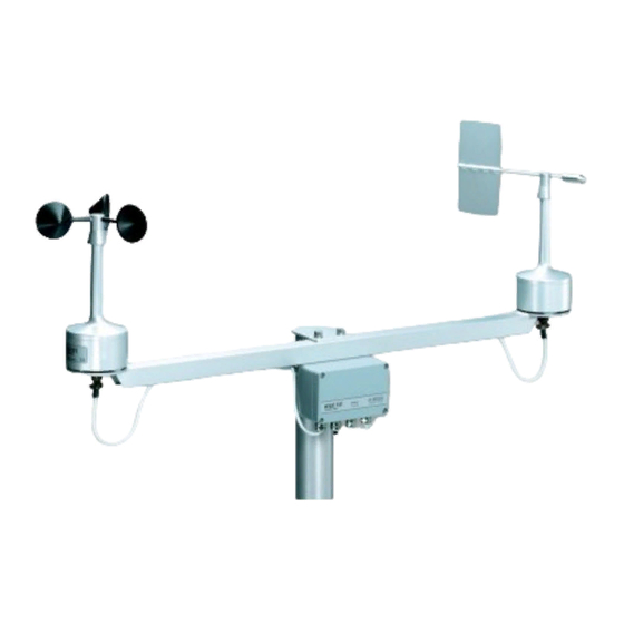
PRODUCT OVERVIEW This chapter introduces WAC151 Cross Arm features. Introduction to WAC151 Cross Arm The WAC151 Cross Arm assembly supports the installation of the Vaisala WAA151 Anemometer and WAV151 Wind Vane, or WAA252 Heated Anemometer and WAV252 Heated Wind Vane. The cross arm assembly consists of a... -
Page 10: Figure 1 Wac151 Cross Arm
User's Guide ________________________________________________________ 0210-033 Figure 1 WAC151 Cross Arm The following numbers refer to Figure 1 above: 1 = Flange for mounting a Vaisala anemometer 2 = Junction box 3 = Flange for mounting a Vaisala wind vane 8 ______________________________________________________ M210349en-A... -
Page 11: Chapter 3 Installation
Chapter 3 __________________________________________________ Installation CHAPTER 3 INSTALLATION This chapter provides you with information that is intended to help you install this product. Selecting Location Allow sufficient clearance for the wind sensors. Wind sensors should not be located next to a building or any other object that might affect the flow of air. -
Page 12: Installation Procedure
User's Guide ________________________________________________________ In general, any object of height (h) will not remarkably disturb wind measurement at a minimum distance of 10 × h. There should be at least 150 m open area in all directions from the mast. Refer to Figure 2 on page 9. 0204-041 Figure 3 Recommended Mast Length on Top of a... -
Page 13: Figure 4 Cable Shield Bent Over The Plastic Sleeve And O-Ring
Chapter 3 __________________________________________________ Installation For installation, follow the procedure below: Remove the four screws holding the cover of the junction box. Remove the cover. Lead the power and signal cables through the cable gland(s). For better protection against RF interference, bend the cable shield as illustrated in Figure 4 below. -
Page 14: Figure 5 Mounting Wac151 To The Top Of A Pole Mast
User's Guide ________________________________________________________ 0206-059 Figure 5 Mounting WAC151 to the Top of a Pole Mast Mount the sensors onto the cross arm. Refer to Figure 6 below. 0110-005 Figure 6 Installation of the Wind Sensors onto WAC151 Cross Arm 12 _____________________________________________________ M210349en-A... -
Page 15: Connections
151 Series Wind Sensors Usually both 151 series wind sensors are connected to the junction box of the WAC151 cross arm simultaneously. Figure 7 on page 14 illustrates the standard wiring diagram for the 151 series wind sensors. The thermostat switch in the upper left corner is always included for temperature control of the shaft heating power. -
Page 16: 252 Series Wind Sensors
BLK to the terminal #5. For the optional sensor power input, connect BRN to the terminal #6. As a power source, it is recommended to use Vaisala WHP25 Mains Power Supply, which has a mast mountable, all-weather enclosure. -
Page 17: Alignment
WAC151, the sensors can only be mounted in one way. Verification If the signal cable from WAC151 is connected to the data collection system and the system is powered up, check that the wind readings react correctly. To test the anemometer, rotate the cups manually. - Page 18 User's Guide ________________________________________________________ This page intentionally left blank. 16 _____________________________________________________ M210349en-A...
-
Page 19: Chapter 4 Maintenance
Chapter 4 ________________________________________________ Maintenance CHAPTER 4 MAINTENANCE This chapter provides information that is needed in basic maintenance of WAC151 Cross Arm. Periodic Maintenance Visual Checking Check every 1 to 2 years that the printed circuit board is not corroded. VAISALA__________________________________________________________17... - Page 20 User's Guide ________________________________________________________ This page intentionally left blank. 18 _____________________________________________________ M210349en-A...
-
Page 21: Chapter 5 Troubleshooting
Heating is not Check the connected. connections. Getting Help For technical questions or for comments on the manuals, contact the Vaisala technical support: E-mail helpdesk@vaisala.com Telephone +358 9 8949 2789 +358 9 8949 2790 VAISALA__________________________________________________________19... -
Page 22: Return Instructions
Pack the faulty product using an ESD protection bag of good quality with proper cushioning material in a strong box of adequate size. Please include the Problem Report in the same box. Send the box to: Vaisala Oyj Contact person / Division Vanha Nurmijärventie 21 FIN-01670 Vantaa Finland... -
Page 23: Chapter 6 Technical Data
Chapter 6 _______________________________________________Technical Data CHAPTER 6 TECHNICAL DATA This chapter provides technical data of WAC151 Cross Arm. Specifications Table 4 WAC151 Cross Arm Specifications Property Description / Value I/O connectors Screw terminal connectors (15 pcs) for the sensors and power lines. - Page 24 *M210349EN*...
Need help?
Do you have a question about the WAC151 and is the answer not in the manual?
Questions and answers