Table of Contents
Advertisement
Quick Links
Advertisement
Table of Contents

Related Manuals for Vaisala RS41


Summary of Contents for Vaisala RS41
- Page 1 M211486EN-E User Guide Ozone Sounding with Vaisala Radiosonde RS41...
- Page 2 This product contains software developed by party without prior written permission of the Vaisala or third parties. Use of the software is copyright holder. Translated documents and governed by license terms and conditions...
-
Page 3: Table Of Contents
Documentation Conventions................8 Trademarks......................8 Product-Related Safety Precautions..............8 Lithium Battery-Related Precautions..............10 1.7.1 Transporting RS41 Radiosondes with Lithium Batteries......10 1.7.2 Transporting Ozone Sensors with Lithium Batteries........11 ESD Protection....................12 Product and System Component Overview......... 13 Introduction to Ozone Sounding with RS41............13 2.1.1... - Page 4 Appendix A: DigiCORA MW41 Ozone Data..........85 Calculating Ozone Data in MW41..............85 Reporting Ozone Data in MW41..............85 Archived Ozone Data in MW41................ 85 A.3.1 Additional Sensor Data from RS41............86 A.3.2 Additional Sensor Data from RS92............86 A.3.3 Calculated Ozone Data ................86 A.3.4...
- Page 5 Attaching Radiosonde to the Holder............57 Figure 43 Pushing the Holder into Place...............58 Figure 44 Radiosonde RS41 Attached to the Holder..........58 Figure 45 SPC Ozone Sensor inside the Flight Box........... 59 Figure 46 EN-SCI Ozone Sensor inside the Flight Box, Cover About to be Closed.......................60...
- Page 6 RS41 User Guide M211486EN-E Figure 51 Securing Unwinder with String (on the Left) or Tape (on the Right)......................64 Figure 52 RSU Stabilizer Attached to the Unwinder..........65 Figure 53 Battery Holder with Lithium Batteries, Wires, and Connector.... 66 Figure 54 Batteries Inserted in the Ozone Sensor Styrofoam Box......66...
- Page 7 Document Versions....................7 Table 2 Related Manuals.....................7 Table 3 OIF411 Terminals....................17 Table 4 Electrical Interface of RS41 and the Additional Sensor......19 Table 5 Ozone Sounding Startup Kit................20 Table 6 Equipment Required for Ozone Destruction Filter........23 Table 7 Equipment Required for Pump Test Unit............. 24 Table 8 Laboratory Ware Needed.................
- Page 8 RS41 User Guide M211486EN-E...
-
Page 9: About This Document
• ECC-6A from Science Pump Corporation. The Vaisala product code is ECC6AB and in MW41 software the sensor is identified with abbreviation SPC. • Model Z from EN-SCI (formerly manufactured by Droplet Measurement Technologies). The Vaisala product code is 252164 and in MW41 software the sensor is identified with abbreviation DMT. 1.2 Version Information Table 1 Document Versions... -
Page 10: Documentation Conventions
Indicates that you need to take some notes during the task. 1.5 Trademarks DigiCORAâ is a registered trademark of Vaisala Oyj. 1.6 Product-Related Safety Precautions Radiosonde RS41 has been tested for safety and approved as shipped from the factory. Note the following precautions:... - Page 11 WARNING! Do not use the radiosonde for any purpose other than for soundings. WARNING! Vaisala recommends the use of parachute even if it is not required by applicable restrictions. WARNING! The chemicals involved in an ozone sounding can be harmful, and must be handled with proper care.
-
Page 12: Lithium Battery-Related Precautions
• DO NOT SPILL WATER ON A BURNING BATTERY. A fire extinguisher must be used. 1.7.1 Transporting RS41 Radiosondes with Lithium Batteries RS41 radiosondes with lithium batteries are classified as: • UN 3091 Lithium metal batteries contained in equipment Consignments must be packed, labeled, and documented according to the IATA packing instructions. -
Page 13: Transporting Ozone Sensors With Lithium Batteries
Chapter 1 – About This Document • The consignment must include a document indicating the lithium content, describing proper handling and procedures for damaged packages, and a telephone number for additional information. Figure 1 Lithium Battery Handling Label If the lithium battery is faulty, do not transport it. 1.7.2 Transporting Ozone Sensors with Lithium Batteries Ozone sensors with lithium batteries are classified as: •... -
Page 14: Esd Protection
RS41 User Guide M211486EN-E 1.8 ESD Protection Electrostatic Discharge (ESD) can damage electronic circuits. Vaisala products are adequately protected against ESD for their intended use. However, it is possible to damage the product by delivering electrostatic discharges when touching, removing, or inserting any objects in the equipment housing. -
Page 15: Product And System Component Overview
2.1 Introduction to Ozone Sounding with RS41 An ozone sounding with RS41 consists of an ozone sensor unit, RSA411 Ozone Interface Kit, and RS41 radiosonde. These are described in the sections below. Other equipment needed is also explained. For detailed information on the radiosonde, see Vaisala Radiosonde RS41-SG and RS41-SGP User Guide. -
Page 16: Figure 2 Spc Ecc-6A Ozone Sensor Parts
RS41 User Guide M211486EN-E Figure 2 SPC ECC-6A Ozone Sensor Parts Gas sampling pump Ozone sensor cathode Ozone sensor anode Wires for interface Air intake tube Motor Connector for pump battery Note that the anode and cathode cells are in a different order in the ECC-6A and Model Z, Figure 3 (page 15). -
Page 17: Ozone Interface Kit Rsa411
Cathode Anode 2.1.2 Ozone Interface Kit RSA411 The RSA411 kit is used with Radiosonde RS41 and Science Pump Corporation’s (SPC) ECC type sensors ECC-6A, or EN-SCI Model Z. The kit contains the items listed below. Figure 4 RSA411 Ozone Interface Kit Contents Radiosonde holder with three plastic dowels and three screws for attaching the holder to the flight box wall. -
Page 18: Figure 5 Ozone Sensor Interface Board Oif411
RS41 User Guide M211486EN-E 2.1.2.1 Ozone Interface Board OIF411 Ozone Interface Board OIF411 has four dedicated channels (ozone sensor current and temperature, battery voltage, and ozone pump current), and an additional voltage measurement channel for other purposes. Figure 5 Ozone Sensor Interface Board OIF411 The terminals on OIF411 are marked with a sticker attached on the card. -
Page 19: Figure 6 Oif411 Terminals Marked On Sticker
Chapter 2 – Product and System Component Overview Figure 6 OIF411 Terminals Marked on Sticker Table 3 OIF411 Terminals Number Connection Cable Code Radiosonde interface CBL210224 Add-on sensor IN for optional XDATA sensors Pump motor CBL210282 Ozone pump motor battery CBL210225 Heating battery CBL210295 Extra terminal SPC sensor W = white cable B = blue... -
Page 20: Figure 7 Oif411 Dimensions
RS41 User Guide M211486EN-E Figure 7 OIF411 Dimensions... -
Page 21: Radiosonde Rs41 Additional Sensor Interface
2.2 Equipment and Material Needed Several items are needed to prepare the ozone sensor and the radiosonde for a flight. The items listed below are included in the Vaisala Ozone Sounding Startup Kit and they are explained in more detail in the sections below:... -
Page 22: Vaisala Ozone Sounding Startup Kit
2.3 Vaisala Ozone Sounding Startup Kit Vaisala part number 25820OS. Vaisala Ozone Sounding Startup Kit is used when preparing a new ozone sounding site. The kit includes materials and equipment for the sounding preparations. A list of the items and their part numbers are provided in Table 5 (page 20). -
Page 23: Ozonizer / Test Unit Ktu-3
A newer digital model is available from EN-SCI. 2.3.1 Ozonizer / Test Unit KTU-3 Vaisala part number 248823. EN-SCI KTU-3 Ozonizer Test Unit is designed for conditioning ECC Ozonesondes with ozone and for checking the performance of the ozonesondes before flight. -
Page 24: Figure 10 Ozonizer/Test Unit Tsc-1
RS41 User Guide M211486EN-E Figure 10 Ozonizer/Test Unit TSC-1 Vaisala recommends adding a digital ampere meter with a minimum resolution of 0.01 uA beside Ozonizer TSC-1, and checking the current from the digital ampere meter instead of the analog meter on TSC-1. -
Page 25: Ozone Destruction Filter
See Performance Review Literature (page 95) Table 6 Equipment Required for Ozone Destruction Filter Item Required Vaisala Part Number Particle and ozone filter: Mine Safety Appliances (MSA) Company. Delivered by 234561 (1 pc) MSA as a single cartridge (part number 815185). -
Page 26: Pump Test Unit
RS41 User Guide M211486EN-E Assemble the ozone destruction filter components as shown in Figure 12 (page 24). Figure 12 Ozone Destruction Filter Catalyst Ultra fiber Funnel Connector tube 1 Connector tube 2 Connector tube 3 Tape 1, 2, and 3 together with electrical tape 2.3.4 Pump Test Unit... -
Page 27: Laboratory Ware Set
The set presented in Table 8 (page 25) is useful and can easily be obtained from any laboratory ware dealer. The set can also be ordered from Vaisala by referring to the part numbers listed in the table. Table 8 Laboratory Ware Needed... -
Page 28: Ozone Chemicals
RS41 User Guide M211486EN-E Item Pieces Vaisala Part Number Cylinder (Pyrex glass) 1 pc, volume 100 ml 12722 (subdivision 1 ml) Volumetric flasks with stoppers 1 pc, volume 1000 ml 12724 (Pyrex glass) 1 pc, volume 500 ml 214857 1 pc, volume 100 ml... -
Page 29: Other Equipment And Material
Chapter 2 – Product and System Component Overview Table 10 Equipment Required for Air Flow Meter Item Required Vaisala Part Number Air flow meter tube. Burette with filling tube, capacity 100 ml 12733 Rubber bulb, capacity approximately from 50 to 80 ml... -
Page 30: Expendables And Spare Parts
RS41 User Guide M211486EN-E 2.3.9 Expendables and Spare Parts After establishing an ozone sounding site, check the availability of expendables and spare parts. Making a list of these items is recommendable. A large variety of spare parts is available from Vaisala. -
Page 31: Constructing An Ozone Sounding
Chapter 3 – Constructing an Ozone Sounding 3. Constructing an Ozone Sounding 3.1 Sounding Preparation Phases and Schedule WARNING! The chemicals involved in an ozone sounding can be harmful, and must be handled with proper care. To ensure your working safety, take all the necessary precautions before beginning the preparations for a flight. -
Page 32: Preparing The Cathode And Anode Solutions
RS41 User Guide M211486EN-E equals to Vaisala I , used in Vaisala scripts. 3.1.1 Preparing the Cathode and Anode Solutions Sensor solution requirements are very strict. The ECC sensor solutions must be prepared using at least Pro Analysis chemicals and triple-distilled water. -
Page 33: Using The Air Flow Meter
Chapter 3 – Constructing an Ozone Sounding 3.2.1 Using the Air Flow Meter This procedure is meant to be carried out with no remarkable breaks (that is, breaks lasting over two hours). To avoid contamination, note the following precautions: Work in a clean environment with clean hands. Never operate the pump without the ozone destruction filter or purified air. -
Page 34: Preparation Steps 7 To 3 Days Prior To Release
RS41 User Guide M211486EN-E Figure 14 Air Flow Rate Measurement Stand Bosshead Connector tube 1 Rubber bulb Flow meter tube Clamp Connector tube 2 Dishwashing liquid Connector tube 3 3.2.2 Preparation Steps 7 to 3 Days Prior to Release To enable smooth operation, place all the necessary parts on a table, but leave some free space in front of the ozonizer, if necessary. -
Page 35: Table 11 Values In Ozonizer
Chapter 3 – Constructing an Ozone Sounding 3. Connect the ozone sensor to the ozonizer (motor, output, sensor leads). a. Turn on the ozonizer. b. Record I before applying any ozone to the sensor: _____________μA 4. Condition the pump and the dry sensor with HI O for 30 minutes. -
Page 36: Preparation Steps On The Day Of Release
RS41 User Guide M211486EN-E After these preparations, a sensor cleaning process takes place, whereby both half cells (anode and cathode) and ionbridge get in balance. 3.3 Preparation Steps on the Day of Release The CAL measurements are applicable when SPC’s TSC-1 Ozonizer/Test unit is used. They can be ignored with the KTU-3 ozonizer. -
Page 37: Preparations Just Before Release (2 - 0 Hours)
Chapter 3 – Constructing an Ozone Sounding 6. After 5 minutes of conditioning with about 5 μA O = μA ________ i = μA________ With NO O , check the sensor response test: : = ________μA i : μA ________0.5 minute 0.51c 0.5s : = ________μA i... -
Page 38: Starting Preparations
RS41 User Guide M211486EN-E Table 12 Workflow for Ozone Sounding Preparations 45 Minutes Before Launch Time to Ozone Sensor Interface Radiosonde Sounding Balloon and Launch in OIF411 RS41 Software MW41 Accessories Minutes Select battery Attach interface Attach Start MW41 Fill the balloon... -
Page 39: Attaching Radiosonde Holder To Flight Box
In the figures presented in this section, the holder is positioned according to Vaisala recommendation, according to which the radiosonde sensor boom is above the flight box wall and the holder is attached on top of the sticker. -
Page 40: Figure 16 Radiosonde Holder Measurements (A) And Position (B)
RS41 User Guide M211486EN-E Figure 16 Radiosonde Holder Measurements (a) and Position (b) -
Page 41: Figure 17 Marking The Positions Of The Holder Screws
Chapter 3 – Constructing an Ozone Sounding 1. The holder is attached on top of the sticker on the flight box wall. Press the radiosonde holder against the flight box wall and mark the holder screw positions with a pen. Figure 17 Marking the Positions of the Holder Screws... -
Page 42: Attaching Oif411 To Spc's Ozone Sensor Frame
RS41 User Guide M211486EN-E 2. Use a screwdriver to insert the dowels where the holder screw marks are. Use the three dowels included in the RSA411 kit. Figure 18 Inserting the Dowels 3. Remove the tape cover before attaching the holder. The tape makes the radiosonde holder attachment extra secure. -
Page 43: Figure 19 Attaching Oif411 To Ozone Sensor
Chapter 3 – Constructing an Ozone Sounding Figure 19 Attaching OIF411 to Ozone Sensor Wing nuts Ozone sensor frame OIF411... -
Page 44: Figure 20 Wing Nuts On The Back Of Oif411
RS41 User Guide M211486EN-E To connect the ozone sensor frame and Ozone Interface Board OIF411: 1. OIF411 is equipped with two wing nuts at the back. Attach OIF411 to the ozone sensor with the wing nuts. See Figure 20 (page 42) for an illustration. -
Page 45: Attaching Oif411 To En-Sci Ozone Sensor Frame
Chapter 3 – Constructing an Ozone Sounding 2. Tighten the wing nuts. Figure 22 OIF411 Wing Nuts Tightened 3.4.4 Attaching OIF411 to EN-SCI Ozone Sensor Frame In addition to OIF411 and the ozone sensor frame, you need the following equipment: • Two M3 nuts included in RSA411 Ozone Interface Kit •... -
Page 46: Figure 23 En-Sci Model Z Sensor
RS41 User Guide M211486EN-E Figure 23 EN-SCI Model Z Sensor To connect the ozone sensor frame and Ozone Interface Board OIF411: 1. Remove the wing nuts attached to OIF411. -
Page 47: Connecting Ozone Sensor Wires To Oif411
Chapter 3 – Constructing an Ozone Sounding 2. Use a drill to make the holes in the ozone sensor frame bigger. Figure 24 Drilling the Ozone Sensor Frame Holes 3. Attach OIF411 to the ozone sensor frame with the two M3 hex nuts, a screw driver and a socket wrench. -
Page 48: Figure 26 Oif411 Terminals Marked On Sticker
RS41 User Guide M211486EN-E Figure 26 OIF411 Terminals Marked on Sticker Table 13 OIF411 Terminals Number Connection Cable Code Radiosonde interface CBL210224 Add-on sensor IN for optional XDATA sensors Pump motor CBL210282 Ozone pump motor battery CBL210225 Heating battery CBL210295 Extra terminal SPC sensor W = white cable, B = blue cable 1. -
Page 49: Preparing The Radiosonde And Oif411
Chapter 3 – Constructing an Ozone Sounding 2. Connet the blue wire from the cathode to the terminal marked with B. Figure 27 Connecting Sensor Wires to OIF411 3.4.6 Preparing the Radiosonde and OIF411 CAUTION! To avoid any problems with the sounding, do not use the sensor loaded (pump-powered) with solutions, if the sensor is not connected to a powered interface, or if the anode and cathode wires are connected. -
Page 50: Figure 28 Connecting Ozone Sensor Pump Cable
RS41 User Guide M211486EN-E • Connect the cable to the OIF411 terminal marked Pump. Figure 28 Connecting Ozone Sensor Pump Cable 3.4.6.2 Connecting Ozone Pump Battery to OIF411 Cable needed: CBL210225 • Connect the ozone pump battery to OIF411 terminal marked Battery (12 ... 20 V). At a later stage, place the battery in the empty compartment on the side of the flight box. -
Page 51: Figure 30 Spc Ecc-6A With Thermistor Assembled
Chapter 3 – Constructing an Ozone Sounding 3.4.6.3 Connecting Thermistor Cable to Ozone Sensor Pump Insert the thermistor into the hole in the pump base of the ozone sensor by pushing the thermistor hose into the hole, as shown in Figure 30 (page 49). -
Page 52: Figure 32 Connecting Heating Battery
RS41 User Guide M211486EN-E 3.4.6.4 Connecting Additional Sensor Cable to OIF411 If you are using an additional sensor in the sounding, use the terminal marked Add-on sensor IN for the additional sensor cable. 3.4.6.5 Connecting Heating Battery to OIF411 (Optional) Cable needed: CBL210295 The heating battery is used in extreme conditions. -
Page 53: Figure 33 Two-Sided Tape Attached To The Battery
Chapter 3 – Constructing an Ozone Sounding 2. Attach two-sided tape to the side and bottom of the battery to attach it to the sensor frame. Figure 33 Two-Sided Tape Attached to the Battery 3. Make sure to pass the battery wires between the ozone sensor frame wall and the ozone sensor top cover and make sure that they are not twisted or under the sensor frame. -
Page 54: Preparing The Radiosonde With Ground Equipment
1. Start MW41 sounding software, if you have not started it yet, and log in. 2. Attach the ozone destruction filter to the pump inlet tube. 3. Place the RS41 radiosonde on the ground check device. The radiosonde is switched on when you place it on the ground check device. The message Preparation in progress will be displayed in MW41. -
Page 55: Figure 35 Ozone Sensor Information
Chapter 3 – Constructing an Ozone Sounding 5. Fill in the information needed and click Apply. During this phase, the radiosonde LED light is red, but you can ignore it. It does not indicate an error at this point. The ASOPOS panel recommends 3.0 cm for cathode solution volume. -
Page 56: Figure 37 Waiting For Background Current
RS41 User Guide M211486EN-E 6. When the message is displayed, remove the Waiting for background current radiosonde from the ground check device. Figure 37 Waiting for Background Current... -
Page 57: Figure 38 Connecting Radiosonde Cable
Chapter 3 – Constructing an Ozone Sounding 7. Connect OIF411 to the radiosonde using cable CBL210224. Do as explained below: a. Connect the radiosonde cable to the interface terminal marked Radiosonde. Figure 38 Connecting Radiosonde Cable b. Connect the interface to the radiosonde. If you are using a radiosonde with EPS covers, you must break a small piece of the EPS cover to get access to the radiosonde interface. -
Page 58: Figure 40 Checking Radiosonde Interface Connector
RS41 User Guide M211486EN-E Before connecting the interface to the radiosonde, check that none of the pins on the radiosonde interface are deformed. Figure 40 Checking Radiosonde Interface Connector After this, firmly push the connector to the interface connector pins located inside... -
Page 59: Figure 42 Attaching Radiosonde To The Holder
2 to 4%. If there are any delays in the sounding preparations or before the sounding starts while the radiosonde is powered from the battery, you can switch off RS41 by pressing the power switch. Switch the radiosonde back on before launching the balloon. -
Page 60: Figure 43 Pushing The Holder Into Place
RS41 User Guide M211486EN-E Figure 43 Pushing the Holder into Place c. If you attach the radiosonde in a lower position than shown here, push the holder against the flight box wall. Figure 44 Radiosonde RS41 Attached to the Holder... -
Page 61: Figure 45 Spc Ozone Sensor Inside The Flight Box
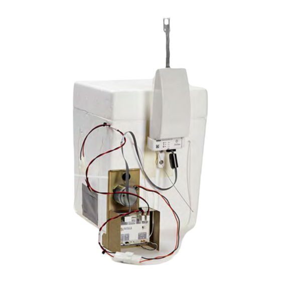
Chapter 3 – Constructing an Ozone Sounding 9. After attaching the radiosonde, place the ozone sensor into the flight box. In this step, item a. below explains inserting SPC ozone sensor to the flight box. See item b. for EN- SCI sensor instructions. -
Page 62: Figure 46 En-Sci Ozone Sensor Inside The Flight Box, Cover About To Be Closed
RS41 User Guide M211486EN-E Figure 46 EN-SCI Ozone Sensor inside the Flight Box, Cover About to be Closed Flight box cover Ozone sensor placed inside the flight box Radiosonde RS41-SG 10. Do not connect the pump motor wires to the battery yet, leave the connectors outside... -
Page 63: Figure 47 Air Outlet Hole And Air Intaketube Not Taped Over
Chapter 3 – Constructing an Ozone Sounding 11. In this step, item a. below explains finalizing the flight box for SPC sensor. See item b. for EN-SCI sensor instructions. a. In case of SPC sensor, close the cover of the flight box and tape the seam between the cover and the body of the box. -
Page 64: Figure 48 Supported Flight Box String In En-Sci Ozone Sensor Flight Box
Figure 55 (page 67) Figure 47 (page 61). The I value equals to Vaisala I , used in Vaisala scripts. Always record the value indoors with destruction filter or ozone-free air connected, and after inserting the ozone sensor to the flight box. -
Page 65: Constructing Sounding Accessories
3.4.8 Constructing Sounding Accessories Note that different installations are used depending on the components of the sounding. Always use an unwinder. An RSU stabilizer must be used if other than Vaisala-specific Totex parachute models are used. Before you begin, see the general instructions and various sounding accessories presented... -
Page 66: Figure 51 Securing Unwinder With String (On The Left) Or Tape (On The Right)
2. As the accidental breaking of the unwinder hook might cause the ozone sounding box to fall with great speed, Vaisala recommends that you tie the unwinder to the parachute spreader with a string for extra security. CAUTION! -
Page 67: Pump Motor Battery
3. Assemble the unwinder detainer to the radiosonde unwinder by pressing the detainer head into the radiosonde unwinder. 4. If you are using other than a Vaisala-specific Totex parachute model, or a radar reflector, connect the RSU stabilizer to the unwinder and prepare the balloon string connection. -
Page 68: Figure 53 Battery Holder With Lithium Batteries, Wires, And Connector
RS41 User Guide M211486EN-E Figure 53 Battery Holder with Lithium Batteries, Wires, and Connector 1. Slide the battery holder into the ECC-6A ozone sensor styrofoam box but leave the battery wires outside. Figure 54 Batteries Inserted in the Ozone Sensor Styrofoam Box Ozone sensors may also use water-activated batteries, which have their own separate activation instructions. -
Page 69: Recording The Surface Ozone
Chapter 3 – Constructing an Ozone Sounding 3. Take the flight box outside and connect the free-hanging battery cable with the ozone sensor battery cable. As the pump is quite noisy, you should be able to hear the ozone sensor pump running. Do not tape over the battery compartment, as the fumes from the battery must be allowed to move out of the box. -
Page 70: Launching The Balloon
RS41 User Guide M211486EN-E 2. Make sure that ozone data is coming through, showing reasonable ozone current and ozone flight box temperature. Figure 56 Viewing Raw Ozone Data in MW41 3.4.11 Launching the Balloon 1. Before launching the balloon, check the MW41 user interface to see that ozone sensor data is received. -
Page 71: Ozone Calculation
Note that the length is defined as the amount of samples. Therefore, different values for radiosondes with different sample rates must be used. A typical value for the window radius for RS41 is 4 (filtering window = 9 seconds). -
Page 72: Ozone Partial Pressure Calculation
RS41 User Guide M211486EN-E 4.3 Ozone Partial Pressure Calculation 4.3.1 Ozone Sensor Operating Principle The ozone sensor used within the ozonesonde is an iodine-iodide redox electrochemical concentration cell. It is made of two bright platinum electrodes immersed in potassium iodide solutions of different concentrations, contained in separate cathode and anode chambers, fabricated from polytetrafluoroethylene (Teflon TFE resin). -
Page 73: Ozone Sensor Reactions
Chapter 4 – Ozone Calculation 4.3.2 Ozone Sensor Reactions The cell system is shown in Figure 57 (page 70). Platinum electrodes are chemically inert, and do not take part in chemical reactions. Electrochemical reactions take place in the boundary layers of the electrodes. As soon as air that contains O molecules is bubbled through the cathode solution, the following total reaction occurs: 2 KI + 0... - Page 74 Correction due to reduced ambient pressure for pump Additional correction factor used in this manual is equal to I used in the Vaisala scripts, and I used in the GAW report 201, and the ASOPOS panel recommendations. Each ozone sensor manufacturer has their own recommendations for calculating I...
- Page 75 The value is entered in the ground equipment during sounding preparations. 4.3.3.3 Measured Airflow Temperature (T All sensors use measured values in a Vaisala application. 4.3.3.4 Pump Efficiency Correction (C The efficiency of the ECC-6A Ozonesonde air sampling pump decreases with altitude.
-
Page 76: Table 14 Ozone Partial Pressure Correction Factors
RS41 User Guide M211486EN-E The ASOPOS panel recommends the use of 3.0 cm only. Table 14 Ozone Partial Pressure Correction Factors Ozone Partial Pressure Correction Factor C Atmospheric Sensor cathode solution volume Sensor cathode solution volume 2.5 cm pressure hPa 3.0 cm 1.160... -
Page 77: Total Ozone Calculation
(for example, total ozone after burst). Table 16 Total Ozone Calculation Item Explanation Total ozone from the sounding Residual total ozone In the software used in Vaisala equipment, the results of total ozone calculation are in Dobson Units (DU). -
Page 78: Total Ozone From Sounding
RS41 User Guide M211486EN-E 4.4.1 Total Ozone from Sounding The total ozone from the sounding is calculated by summing up the amount of ozone in the layers between two measurement points as expressed in the equation below. When using the units indicated in the list below, the equation gives the total ozone in units of grams per square meter (g/m Table 17 Total Ozone from Sounding... -
Page 79: Residual Ozone (Total Ozone After Balloon Burst)
Chapter 4 – Ozone Calculation The following equation gives the result in DUs when the partial pressures are given in mPa and ambient pressures in hPa. 4.4.2 Residual Ozone (Total Ozone after Balloon Burst) After the balloon burst, the level of ozone is estimated by using the equation below with a constant mixing ratio (p ) up to ambient pressure 0 hPa. - Page 80 RS41 User Guide M211486EN-E The ideal gas law is ×V × R × T where partial pressure of ozone in mPa mole number of ozone ideal gas constant temperature in K gives Combining the equations gives where Molar mass of ozone, 48.00 g/mol...
-
Page 81: Accuracy Of Ozonesonde Measurement
Relevant literature is also available. Performance Review Literature (page 95). The latest detailed technical data for the radiosonde and OIF411 can be found on the Vaisala website, www.vaisala.com. Detailed specifications for the ozone sensors are available directly from the manufacturers or from Vaisala. - Page 82 RS41 User Guide M211486EN-E...
-
Page 83: Ozone Interface Board Oif411 Data Interpretation
Chapter 5 – Ozone Interface Board OIF411 Data Interpretation 5. Ozone Interface Board OIF411 Data Interpretation 5.1 Measurement Data When Radiosonde RS41 is connected to Ozone Interface Board OIF411, it sends the OIF411 measurement data through the additional sensor interface. The following information is contained: • Instrument type and number •... -
Page 84: Additional Data
RS41 User Guide M211486EN-E • Software version once per minute OIF411 ID data replaces OIF411 measurement data, but not the additional sensor data, sent once per minute. The OIF411 ID data contains the following information: xdata= <Instrument type is 05><Instrument number is 01><OIF serial number><diagnostics word><SW version><I>CR. -
Page 85: Storage And Transportation
6.2 Transportation Vaisala radiosondes must be transported in their original shipping packages. These packages are designed and built to survive and protect their contents in the environmental conditions described herein with the terminology and standards per standard IEC 60721-3-2. - Page 86 RS41 User Guide M211486EN-E...
-
Page 87: Appendix A: Digicora Mw41 Ozone Data
Appendix A – DigiCORA MW41 Ozone Data Appendix A. DigiCORA MW41 Ozone Data A.1 Calculating Ozone Data in MW41 Ozone data is calculated by the scripting engine using raw ozone and EDT data. This information, along with the calculated ozone, can be archived for further inspection, for example, simulation. -
Page 88: Additional Sensor Data From Rs41
RS41 User Guide M211486EN-E A.3.1 Additional Sensor Data from RS41 Table 20 AdditionalSensorData Column Name Type Description SOUNDINGIDPK String Unique sounding ID RADIORXTIMEPK Double Radio time [s] INSTRUMENTTYPEPK String Instrument type identifier INSTRUMENTNUMBERPK String Instrument number MEASUREMENTOFFSET Double Measurement time offset of the... -
Page 89: Oif411 Or Oif92 Ozone Parameters
Appendix A – DigiCORA MW41 Ozone Data Column Name Type Description PARTIALPRESSURE Double Calculated ozone partial pressure [mPa] BOXTEMPERATURE Double Sensor box temperature [Kelvin] O3CURRENT Double Bias and pressure corrected current [uA] INTEGRATEDOZONE Double Ozone accumulated up to the current sounding level [DU] (Dobson Unit) RESIDUALOZONE Double... -
Page 90: Ozone Results
RS41 User Guide M211486EN-E Column Name Type Description IREFZEROC Double OIF411: null OIF92: Iref at 0 C temperature [uA] RNTC25 Double OIF411: null OIF92: Sensor thermistor resistance at 25 C temperature [Ohm] VREFCH3 Double OIF411: null OIF92: Reference value for voltage... -
Page 91: Raw Ozone Data
Appendix A – DigiCORA MW41 Ozone Data Column Name Type Description OZONEPRIORSTART Double Ozone at the surface level prior to the launch [DU] (Dobson Unit) PRIORSTARTMEASDURATION Double Surface ozone measurement duration [min] A.3.6 Raw Ozone Data Ozone layer data without pressure correction. Table 25 RawOzone Column Name Type... - Page 92 RS41 User Guide M211486EN-E...
-
Page 93: Appendix B: Safety Instructions For Balloon Operators
Appendix B – Safety Instructions for Balloon Operators Appendix B. Safety Instructions for Balloon Operators Photocopy these instructions and place the list in clear view in the balloon filling shed and in the sounding compartment. WARNING! New operator! Carefully study the instructions for using the hydrogen generator and for the correct method of inflation. - Page 94 RS41 User Guide M211486EN-E 14. Always keep the radiosonde at least 50 cm below the level of the gas nozzle and the inflated balloon, and at least 1.5 meters away from the gas cylinder/hydrogen generator, connectors, and tubing. Avoid taking the radiosonde inside the balloon filling shed, if possible.
-
Page 95: Appendix C: Checklist For Equipment And Supplies For Flight Preparations
Table 26 Checklist for Equipment Equipment Checked Ozone sensor with styrofoam flight box and motor battery Radiosonde RS41 Ozone Interface Board OIF411 Balloon (plastic or rubber) 5 meters of string (strength about 300 to 500 N), an unwinder and a detainer... - Page 96 RS41 User Guide M211486EN-E Equipment Checked Pair of lint-free gloves for laboratory work (made of artificial fabric or plastic, disposable)
-
Page 97: Appendix D: Performance Review Literature
Appendix D – Performance Review Literature Appendix D. Performance Review Literature Table 27 Performance Review Literature Name Details Attmannspacher, W. and H.U. Dütsch International Ozone Sonde Intercomparison at Observatory Hohenpeissenberg. Bericht des Deutschen Wetterdienstes, No. 120, 1970, 85 pp. Attmannspacher, W and H.U. Dütsch 2nd. - Page 98 RS41 User Guide M211486EN-E Name Details Kley, D., H.G.J. Smit, H. Vömel, H. Tropospheric water-vapour and ozone cross-sections in a zonal plane Grassl, V. Ramanathan, P.J. Crutzen, S. over the equatorial Pacific Ocean, Q.J.R. Meteorol. Soc. (1997), 123, Williams, J. Meywerk, S.J. Oltmans pp.
- Page 99 Appendix D – Performance Review Literature Name Details Stübi R., G. Levrat, B. Hoegger, P. In-flight comparison of Brewer-Mast and electrochemical Viatte, J. Staehelin, F. J. Schmidlin concentration cell ozonesondes, J. Geophys. Res., 113, D13302, doi:10.1029/2007JD009091. 2008. Third WMO intercomparison of the ozonesondes used by the Global ozone observing System, Vanscoy Canada 13-24 May 1991, WMO/ Global Atmosphere Watch/WMO Global Ozone Research and Monitoring Project, Report No 27.
- Page 100 RS41 User Guide M211486EN-E...
-
Page 101: Technical Support
Vaisala recommends that you include a problem report when contacting Vaisala technical support. For more information, see AWS310-SITE Configuration and Maintenance Manual. Vaisala Service Centers perform calibrations and adjustments as well as repair and spare part services. For Vaisala Service Center contact information, see www.vaisala.com/... - Page 102 RS41 User Guide M211486EN-E...
- Page 104 www.vaisala.com...
Need help?
Do you have a question about the RS41 and is the answer not in the manual?
Questions and answers