Vaisala WINDCAP WMT700 Series User Manual
Ultrasonic wind sensor
Hide thumbs
Also See for WINDCAP WMT700 Series:
- User manual (221 pages) ,
- Quick reference manual (36 pages) ,
- Technical notes (4 pages)
Table of Contents
Advertisement
Quick Links
Advertisement
Table of Contents

Related Manuals for Vaisala WINDCAP WMT700 Series


Summary of Contents for Vaisala WINDCAP WMT700 Series
- Page 1 USER'S GUIDE Vaisala WINDCAP® Ultrasonic Wind Sensor Series WMT700 M211095EN-C...
- Page 2 The contents are subject to change without prior notice. Please observe that this manual does not create any legally binding obligations for Vaisala towards the customer or end user. All legally binding commitments and agreements are included exclusively in the applicable supply contract or Conditions of...
-
Page 3: Table Of Contents
Host System Connections and Interfaces ......33 CHAPTER 4 INSTALLATION.................... 35 Selecting Location for Representative Measurements ..35 Installation Procedure............38 Unpacking Instructions............39 Mounting................40 Mounting on Vertical Pole Mast ........40 Mounting on Horizontal Cross Arm ........ 44 VAISALA ________________________________________________________________________ 1... - Page 4 USER'S GUIDE____________________________________________________________________ Checklist for Connection Cables .........47 Alignment................48 Alignment tuning.............50 Installing Bird Cage .............50 Wiring..................52 Cables .................52 Cable 2m and Cable 10m............53 Note for wiring RS485 for COM2 ........54 RS485 Cable 2m and RS485 Cable 10m ......54 Connector Signals ...............55 Heating..................57 Heated Transducers ............57 Heated Transducers and Arms ...........58...
- Page 5 Visual Inspection..............106 Cleaning ................106 Testing Proper Operation ............ 106 CHAPTER 9 TROUBLESHOOTING ................109 Problem Situations............... 109 Error and Event Messages ..........111 Restoring Serial Port Settings ..........112 Technical Support ..............114 Product Returns ..............114 VAISALA ________________________________________________________________________ 3...
- Page 6 USER'S GUIDE____________________________________________________________________ CHAPTER 10 TECHNICAL DATA ..................115 Dimensions ................119 APPENDIX A COMPLETE COMMAND SET FOR WMT700..........121 APPENDIX B TYPICAL SYSTEM ENVIRONMENTS............123 APPENDIX C DEFAULT SETTINGS FOR DIFFERENT DIGITAL COMMUNICATION PROFILES ....................127 APPENDIX D CONFIGURATION PARAMETERS ............129 4 ___________________________________________________________________ M211095EN-C...
- Page 7 System Environment with Serial Port COM1 Only....123 Figure 34 System Environment with Analog Output Only ...... 124 Figure 35 System Environment with Serial Ports COM1 and COM2 ..125 Figure 36 System Environment with Backup Battery ......126 VAISALA ________________________________________________________________________ 5...
- Page 8 USER'S GUIDE____________________________________________________________________ This page intentionally left blank. 6 ___________________________________________________________________ M211095EN-C...
- Page 9 Wind Direction ................ 115 Table 30 Outputs ................... 116 Table 31 General................... 117 Table 32 Accessories ................118 Table 33 Command Set for All Profiles Supported by WMT700... 121 Table 34 Default Settings for Different Digital Communication Profiles..................127 VAISALA ________________________________________________________________________ 7...
- Page 10 USER'S GUIDE____________________________________________________________________ This page intentionally left blank. 8 ___________________________________________________________________ M211095EN-C...
-
Page 11: Chapter 1 General Information
This chapter provides general notes for the manual and the WMT700 series. About This Manual This manual provides information for installing, operating, and ® maintaining Vaisala WINDCAP Ultrasonic Wind Sensors WMT701, WMT702, and WMT703. Contents of This Manual This manual consists of the following chapters: - Chapter 1, General Information, provides general notes for the manual and the WMT700 series. -
Page 12: Version Information
Updated names of accessories and cables. M211095EN-A June 2010. First version. Related Manuals Table 2 Related Manuals Manual Code Manual Name ® M211097EN Upgrading from Vaisala WINDCAP Ultrasonic Wind Sensor WS425 to WMT700 Technical Reference 10 __________________________________________________________________ M211095EN-C... -
Page 13: Documentation Conventions
If ice or snow accumulates on WMT700 or the mast, it can fall and cause injury to persons below. WARNING Some WMT700 product versions provide heating for transducers and/or array arms. To avoid injury, do not touch the heated parts of the wind sensor when the heating is enabled. VAISALA _______________________________________________________________________ 11... - Page 14 USER'S GUIDE____________________________________________________________________ WARNING Make sure that you connect only de-energized wires. WARNING Using a long cable between different units (sensors, transmitters, power supplies, and displays) can cause a lethal surge voltage, if a lightning strike occurs in the vicinity. Always apply proper grounding procedures and follow the requirements of the local Electrical Code.
-
Page 15: Recycling
1:2006 (Electrical equipment for measurement, control and laboratory use - EMC requirements for use in industrial locations) and EN 60945:2002 (Maritime Navigation and Radiocommunication Equipment and Systems - General Requirements - Methods of Testing and Required Test Results). VAISALA _______________________________________________________________________ 13... -
Page 16: Trademarks
Microsoft Corporation in the United States and/or other countries. Warranty For certain products Vaisala normally gives a limited one-year warranty. Visit our Internet pages for more information and our standard warranty terms and conditions: www.vaisala.com/services/warranty.html. -
Page 17: Chapter 2 Product Overview
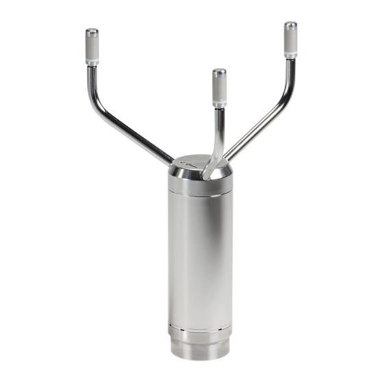
Ultrasonic Wind Sensor WMT700 measures wind speed and direction and sends the measurement results to data acquisition systems. WMT700 forms part of the Vaisala weather measurement offering suitable for systems and stand-alone installations. The WMT700 series consists of three product types with different measurement ranges: WMT701, WMT702, and WMT703. -
Page 18: Figure 1 Wmt700 Wind Sensor
USER'S GUIDE____________________________________________________________________ user also has a wide range of configuration options for the wind sensor and the measurement settings. WMT700 can be equipped with accessories to tailor the instrument to match to different user-specific needs. The accessories include a bird deterrent solution and a field usable calibration verifier. -
Page 19: Figure 2 Wmt700 Wind Sensor From Below
The following numbers refer to Figure 2 above: 1 = Waterproof vent 2 = Mounting adapter screw (3pcs, 4mm Allen key) 3 = 17-pin M23 male connector NOTE Do not open the sensor. There are no user-serviceable parts inside. VAISALA _______________________________________________________________________ 17... -
Page 20: Figure 3 Fix70 Mounting Kit
USER'S GUIDE____________________________________________________________________ 1104-064 Figure 3 FIX70 Mounting Kit The following numbers refer to Figure 3 above: FIX70 consists of : 1 = Fix body 2 = Removable mast guide with mounting hardware 3 = Mounting hardware (M6 nuts, washers type ) 4 = U bolts for ø30 mm mast (2 pcs) 5 = U bolts for ø60 mm mast (2 pcs) 18 __________________________________________________________________ M211095EN-C... -
Page 21: Ordering Options For Wmt700 Series
Transducer and array arm heating: 150 W (minimum 200 W needed) NOTE Vaisala recommends using heated versions of WMT700 in environmental conditions where snow and ice build-up is possible. For more information on the heating functionality, see section Heating on page 57. -
Page 22: Accessories
USER'S GUIDE____________________________________________________________________ Accessories WMT700 can be tailored to the need with several accessories. The accessories include, for example, several mounting adapters for different mast diameters, cables for different host systems and preferred communication types, bird prevention and field calibration kits. When specifying your WMT700, you can order the optional FIX70 universal mounting adapter, a bird cage, WMT700 verifier, and cables as accessories for WMT700. -
Page 23: Bird Cage
Chapter 2 __________________________________________________________ Product Overview Bird Cage Vaisala recommends using the optional bird cage in areas with large bird populations. The cage is designed to prevent large birds from disturbing the measurement. It has been tested in a wind tunnel with wind speeds of up to 40 m/s without noticeable effects on the wind speed and direction measurement. -
Page 24: Wm Verifier
USER'S GUIDE____________________________________________________________________ WM Verifier The optional verifier is a small echo-free chamber for testing the mechanical integrity of WMT700 and performing one-point calibration. The verifier ensures that the array is undamaged and the transducers are parallel to each other. You can perform the verifier test in a laboratory or in the field. -
Page 25: Cables
MAWS cable 10 m Used for connecting WMT700 to Vaisala Automatic Weather Station MAWS. 229807SP AWS520 cable 10 m, shield Used for connecting WMT700 to Vaisala Fixed connected to PE pin Site Observation System AWS520. 227566SP AWS520 cable 10 m, shield not... - Page 26 USER'S GUIDE____________________________________________________________________ This page intentionally left blank. 24 __________________________________________________________________ M211095EN-C...
-
Page 27: Functional Description
FUNCTIONAL DESCRIPTION This chapter describes the functionality of WMT700. Operating Principle ® WMT700 uses the Vaisala WINDCAP ultrasonic sensor technology in wind measurement. The sensor has an onboard microcontroller that captures and processes data and communicates over serial interfaces. The wind sensor has an array of three equally spaced ultrasonic transducers on a horizontal plane. -
Page 28: Figure 6 Ultrasonic Measurement Principle
USER'S GUIDE____________________________________________________________________ 1005-007 Figure 6 Ultrasonic Measurement Principle The following numbers refer to Figure 6 above: 1 = Ultrasonic measurement with zero wind. 2 = Impact of tail wind on ultrasonic measurement. 3 = Impact of head wind on ultrasonic measurement. 26 __________________________________________________________________ M211095EN-C... -
Page 29: Figure 7 Measurement Paths Of Wmt700
Figure 7 below shows the different paths of WMT700 and the vectors provided by the wind sensor: 1104-066 Figure 7 Measurement Paths of WMT700 where: = Measurement paths 1 to 6 of WMT700. = The distance between two transducers. VAISALA _______________________________________________________________________ 27... -
Page 30: Coordinate Systems: Vector And Polar Calculations
USER'S GUIDE____________________________________________________________________ The vectors are calculated as follows: (1/A (1/A (1/A The equation depends on the accurate distance of the measurement path (L). The computed wind speeds are independent of altitude, temperature and humidity, which are cancelled out when the transit times are measured in both directions, although the individual transit times depend on these parameters. -
Page 31: Wind Speed And Direction Averaging
The default gust averaging interval is 3 seconds, as recommended by the WMO (World Meteorological Organization). If scalar averaging has been selected, you can also enable wind direction coasting to ensure consistent direction measurement results at low wind speeds. VAISALA _______________________________________________________________________ 29... -
Page 32: Scalar Averaging
USER'S GUIDE____________________________________________________________________ Scalar Averaging When scalar averaging has been selected, WMT700 calculates wind speed and direction averages by adding up each wind measurement from the averaging time and then dividing the sum by the number of measurements. The time between each consecutive wind speed and wind direction measurement is 0.25 seconds. -
Page 33: Wind Direction Coasting
If the data acquisition system requests data before the initial averaging time completes, the sensor returns the most recent complete measurement data. VAISALA _______________________________________________________________________ 31... -
Page 34: Measurement Methods
USER'S GUIDE____________________________________________________________________ Measurement Methods WMT700 measures wind speed and direction either continuously or for the duration of the user-configurable averaging time. You can select the measurement mode over the serial interface. Continuous Measurement You can set WMT700 to measure wind data continuously until the sensor receives the STOP command. -
Page 35: Host System Connections And Interfaces
In a split-supply system there can be a separate backup power supply for the operations power supply. Figure 10 on page 34 shows the main software components and external interfaces of WMT700. VAISALA _______________________________________________________________________ 33... -
Page 36: Figure 10 External Interfaces Of Wmt700
USER'S GUIDE____________________________________________________________________ Figure 10 External Interfaces of WMT700 NOTE For examples of typical system environments for WMT700, see Appendix B, Typical System Environments, on page 123. 34 __________________________________________________________________ M211095EN-C... -
Page 37: Chapter 4 Installation
This chapter contains information that is needed to install WMT700 with the FIX70 mounting kit. If you are upgrading from WS425 to WMT700 and using a WS425 NOTE ® mounting kit, see Upgrading from Vaisala WINDCAP Ultrasonic Wind Sensor WS425 to WMT700 Technical Reference. Selecting Location for Representative Measurements Finding a suitable site for WMT700 is important for getting representative ambient measurements. -
Page 38: Figure 11 Recommended Location For Wmt700 In Open Area
USER'S GUIDE____________________________________________________________________ Figure 11 below. Note that you should follow application-specific installation guidelines. When mounting two WMT700s at the same height, make sure that there is a minimum of 10 meters of distance between the two devices. If the difference in the height of the sensors is at least 0.5 meters, it is enough to have a minimum distance of 2 meters between the two devices to avoid possible acoustical interference between them. -
Page 39: Figure 12 Recommended Mast Length For Wmt700 On Top Of Building
Do not install the wind sensor above the top of the lightning protection rod. WARNING Do not install WMT700 when there is a risk of thunderstorm or lightning activity in the area. VAISALA _______________________________________________________________________ 37... -
Page 40: Installation Procedure
USER'S GUIDE____________________________________________________________________ Figure 13 Minimum Distance between two WMT700s Installed at Same Height Installation Procedure At the measurement site, WMT700 needs to be mounted, aligned, and connected to the power source and data acquisition system. You can install the optional bird cage after the wind sensor has been mounted and the transportation damper has been removed from the sensor. -
Page 41: Unpacking Instructions
WMT700. Figure 15 on page 40 shows the damper protecting the array. Retain all original packaging in case you have to return WMT700 to Vaisala Service Center for maintenance purposes. WMT700 is uninstalled by performing the steps of the mounting procedure in reverse order. -
Page 42: Mounting
USER'S GUIDE____________________________________________________________________ 1005-025 Figure 15 WMT700 and Transportation Damper NOTE Save the container and all the packaging materials for future transporting or shipping. Mounting You can mount WMT700 either to a vertical pole mast or a horizontal cross arm. Each of the mounting options is further described in the following sections. - Page 43 WMT700 is now ready for operation. NOTE When installing WMT700 to the side of a mast, make sure that the mounting kit is positioned at the top level of the mast. See Figure 16 on page 42. VAISALA _______________________________________________________________________ 41...
-
Page 44: Figure 16 Wmt700 On Side Of Pole Mast
USER'S GUIDE____________________________________________________________________ 1006-077 Figure 16 WMT700 on Side of Pole Mast The following numbers refer to Figure 16 above: FIX70 mounting kit WMT700 wind sensor Mounting screw in final position U bolt and a nut (M8DIN934-A4) in horizontal slot 42 __________________________________________________________________ M211095EN-C... -
Page 45: Figure 17 Wmt700 On Top Of Pole Mast
Figure 17 WMT700 on Top of Pole Mast The following numbers refer to Figure 17 above: WMT700 wind sensor Mounting screw in final position North arrow U bolt and a nut (M8DIN934-A4) in horizontal slot FIX70 mounting kit VAISALA _______________________________________________________________________ 43... -
Page 46: Mounting On Horizontal Cross Arm
USER'S GUIDE____________________________________________________________________ Mounting on Horizontal Cross Arm When mounting WMT700 to a cross arm, the wind sensor can be placed with the array facing up or down. Mounting WMT700 with the array facing down provides additional protection against the accumulation of snow and interference from birds. -
Page 47: Figure 18 Wmt700 On Cross Arm With Array Facing Up
WMT700 on Cross Arm with Array Facing Up The following numbers refer to Figure 18 above: WMT700 wind sensor Mounting adapter FIX70 mounting kit Mounting screw in final position U bolt and a nut (M8DIN934-A4) in vertical slot North arrow VAISALA _______________________________________________________________________ 45... -
Page 48: Figure 19 Wmt700 On Cross Arm With Array Facing Down
USER'S GUIDE____________________________________________________________________ 1006-080 Figure 19 WMT700 on Cross Arm with Array Facing Down The following numbers refer to Figure 19 above: FIX70 mounting kit. WMT700 wind sensor. 46 __________________________________________________________________ M211095EN-C... -
Page 49: Checklist For Connection Cables
Too much strain may cause the cable to fall off, damage the cable or connector, or make the cable or connector susceptible to water leakage. The recommended minimum bending radius for the cable is 70 mm. VAISALA _______________________________________________________________________ 47... -
Page 50: Alignment
USER'S GUIDE____________________________________________________________________ WARNING Make sure that you connect only de-energized wires. WARNING Using a long cable between different units (sensors, transmitters, power supplies, and displays) can cause a lethal surge voltage, if a lightning strike occurs in the vicinity. Always apply proper grounding procedures and follow the requirements of the local Electrical Code. -
Page 51: Figure 21 Correctly Aligned Wmt700
Figure 21 Correctly Aligned WMT700 1001-018 Figure 22 Incorrectly Aligned WMT700 and Resulting Offset Error where N = The correct direction for true north. α = The wind direction offset error caused by the misalignment of WMT700. VAISALA _______________________________________________________________________ 49... -
Page 52: Alignment Tuning
To install the bird cage, you need to position the bird cage on top of the wind sensor and secure the kit with two straps. You can order the cage as an accessory from Vaisala, see Table 32 on page 118. The required straps are provided with the bird cage. -
Page 53: Figure 4 Bird Cage
Bird Cage and Bird Cage Straps The following numbers refer to Figure 23 above: 1 = Bird cage 2 = Bird cage straps 3 = Wind sensor 4 = Guide for attaching the straps 5 = Latch for securing the straps VAISALA _______________________________________________________________________ 51... -
Page 54: Wiring
Ready-made cables are available for use with Vaisala MAWS and AWS520 systems. These cables have connectors on both ends. There is also a retro-fit cable for Vaisala ROSA system in case analog output has been used with WS425. Vaisala provides open-lead cables for connections to other host systems:... -
Page 55: Cable 2M And Cable 10M
Analog Output Ground Red-Blue COM port RS-232 RS-422 RS-485 SDI-12 RS232Rx RxB Green RS232Tx TxB Data Yellow COM2 Brown-Green 14 White-Yellow COM1 and COM2 Communication Ports Ground Violet RS-485, B Black COM1 (service port) RS-485, A Brown-Yellow 16 VAISALA _______________________________________________________________________ 53... -
Page 56: Note For Wiring Rs485 For Com2
USER'S GUIDE____________________________________________________________________ Note for wiring RS485 for COM2 In RS485 mode, the same signals as in RS422 mode are available at the end of Cable 2m and Cable 10m. Make two-wire loop-backs at the end of the cable, as shown in Table 9 and Figure 24 below. Table 9 COM2 RS485 Wiring WMT700 Signals... -
Page 57: Connector Signals
Figure 25 on page 56 and Table 11on page 56 describe the pin-out of the 17-pin M23 connector as seen from the outside. The serial output type of COM2 depends on the sensor configuration. Analog outputs are always available from the connector. VAISALA _______________________________________________________________________ 55... -
Page 58: Figure 25 Pins For 17-Pin M23 Connector
USER'S GUIDE____________________________________________________________________ 1103-061 Figure 25 Pins for 17-pin M23 Connector Table 11 Pin-out for 17-pin M23 Connector Description RS-232 RS-422 RS-485 SDI-12 Operating Power Supply Analog output AOUT2, Wind Direction RS232Rx COM2 RS232Tx Data Heater Power Supply Heater Power Supply Heater Power Supply Ground Heater Power Supply Ground COM1 (Service Port) -
Page 59: Heating
At mid-range, two of the transducers are heated. At high voltage end, a single transducer is heated at a time. A PWM (Pulse Width Modulation) is used to control the average heating power. VAISALA _______________________________________________________________________ 57... -
Page 60: Heated Transducers And Arms
USER'S GUIDE____________________________________________________________________ Heated Transducers and Arms In addition to heated transducers, the array arms can also be heated, which prevents ice build-up on the arms. The functional principle is the same as with the heated transducers only, but the maximum heating power is limited to 200W and the average heating power is limited to 150W. -
Page 61: Figure 26 Wmt700 Operating Supply Current Consumption
Chapter 4 _______________________________________________________________ Installation 1104-054 Figure 26 WMT700 Operating Supply Current Consumption 1104-055 Figure 27 WMT700 Operating Supply Power Consumption VAISALA _______________________________________________________________________ 59... -
Page 62: Heating Power
USER'S GUIDE____________________________________________________________________ Heating Power Table 12 below lists the power supply requirements of each WMT700 heating option. Table 12 Heating Power Supply Requirements for WMT700 Series Heating Option Heating Voltage Required Heating Power Supply None Transducers 24/36 VDC 40 W Transducers and arms 24 VDC 200 W... -
Page 63: Serial Communication And Analog Output
- COM1: Service port (RS485) Both ports support the same commands, protocols, operations, and data messages. Any computer or data logger that has a serial port can be used to send commands to WMT700 and receive measurement data. VAISALA _______________________________________________________________________ 61... -
Page 64: Digital Communication Interface
USER'S GUIDE____________________________________________________________________ Digital Communication Interface COM2 is a flexible digital communication interface that is preconfigured according to your order. The available options are: - RS-232 - RS-485 - RS-422 - SDI-12 COM1 is a fixed RS-485 communication interface intended to be used as a service port. -
Page 65: Protocols
Chapter 5 _______________________________________ Serial Communication and Analog Output The ROSA - MES12 profile is intended for connecting WMT700 to Vaisala ROSA system. The WS425 profiles can be used when upgrading from the WS425 wind sensor to WMT700. For a list of the serial commands available for all communication profiles supported by WMT700, see Appendix A, Complete Command Set for WMT700 on page 121. -
Page 66: Serial Interface Timing
USER'S GUIDE____________________________________________________________________ Figure 28 below shows the configuration and measurement modes of both serial ports provided by WMT700. 1001-111 Figure 28 Configuration and Measurement Modes for WMT700 After power-up WMT700 is in measurement mode. To change settings, use the OPEN command to enter configuration mode. When you have changed the settings, use the CLOSE command to exit configuration mode. -
Page 67: Analog Output
To emulate the WS425 analog output, choose voltage output, frequency output, and potentiometer. For more detailed instructions, see Upgrading ® from Vaisala WINDCAP Ultrasonic Wind Sensor WS425 to WMT700 Technical Reference. For information on wiring, see section Wiring on page 52. -
Page 68: Analog Output Types
USER'S GUIDE____________________________________________________________________ Analog Output Types Analog output for Wind Speed (AOUT1) can be configured as: - Voltage output. - Current output. - Frequency output. Analog output for Wind Direction (AOUT2) can be configured as: - Voltage output. - Current output. - Potentiometer output. -
Page 69: Table 15 Common Transfer Function Settings For Aout1 (Ws)
= Produced analog output (V, A, Hz, 100 %) = Measured wind direction or speed (in m/s or °). k = Selected gain value. y0 = Selected offset value. In frequency mode this value is 0. VAISALA _______________________________________________________________________ 67... -
Page 70: Limitations For Output Signals
USER'S GUIDE____________________________________________________________________ Example 1 - Output mode: voltage - Offset: 0.0 - Gain: 0.1 With the above settings, the analog output voltage range is from 0 V (0 m/s) to 7.5 V (75 m/s). When the measured wind speed is 10 m/s, the output voltage is 1.0 V. -
Page 71: Missing Readings And Error Indication
The default error indication is an out-of-range signal, which is more than 10 V or 20 mA but other error settings can also be configured. You can also disable error indication if necessary. For more information, see section Configuration Parameters on page 81. VAISALA _______________________________________________________________________ 69... - Page 72 USER'S GUIDE____________________________________________________________________ This page intentionally left blank. 70 __________________________________________________________________ M211095EN-C...
-
Page 73: Configuration Commands
It is also possible to use one serial port in configuration mode while operating WMT700 from the other serial port. In WMT700, there are commands for: - Parameters handling - Wind measurement control - Diagnostics - Information VAISALA _______________________________________________________________________ 71... -
Page 74: Table 17 List Of Configuration Mode Commands
USER'S GUIDE____________________________________________________________________ At the end of each command, press ENTER to execute the command. For a successful execution, the following combinations of Carriage Return <CR> and Line Feed <LF> are accepted: - <CR> - <LF> - <CR><LF> You can send commands at any Baud rate. The command is executed when end-of-line character is received. -
Page 75: Prerequisites For Serial Connection
Send line ends with line feed. Click OK and close the New Connection Properties window. On the View menu, click Font. In the Font list, select Terminal. From the Call menu, click Call. Enter a name and select an icon for the connection. Click OK. VAISALA _______________________________________________________________________ 73... -
Page 76: Mode Switching Commands
USER'S GUIDE____________________________________________________________________ Mode Switching Commands OPEN — Entering Configuration Mode Switch the sensor power supply on. The following information is displayed: wmt700 v.<version number> Wait for 4 seconds. Then use the following command to enter configuration mode: $0OPEN After a successful OPEN command, the following symbol is displayed: >... - Page 77 1 mA/m/s and the offset to 4 mA. S aout1_o,0.004 S aout1_g,0.001 S aout1mode,0 Example 3 In this example both analog outputs are disabled to reduce power consumption. S aout1mode,3 S aout2mode,7 VAISALA _______________________________________________________________________ 75...
-
Page 78: G - Get Parameter
USER'S GUIDE____________________________________________________________________ G — Get Parameter This command shows the values of the configuration parameters. You can either display all parameter values or only certain values. For a list of available parameters, see Table 18 on page 82. Get All Parameters You can use the G command to view all parameter values if you do not specify any parameters in the command. -
Page 79: Display Port Settings
MEAS — Single Wind Measurement This command starts wind measurement based on the user-configurable averaging time. WMT700 does not send the data message automatically. Use the polling command to fetch measurement data in the required data message format. MEAS VAISALA _______________________________________________________________________ 77... -
Page 80: Start - Start Continuous Measurement
USER'S GUIDE____________________________________________________________________ START — Start Continuous Measurement This command starts continuous wind measurement. Continuous measurement starts when you exit configuration mode or restart WMT700. You can retrieve data with a polling command or configure WMT700 to send data messages at selected intervals. You can set the interval for automatic messages with the autoInt parameter. -
Page 81: Clearerr - Reset Error Codes And Counts
- The code for the most recent error: 13 If no errors or events have occurred yet, the response is the following: 0,0,0,0,0,0 CLEARERR — Reset Error Codes and Counts This command resets the error counters of WMT700. CLEARERR VAISALA _______________________________________________________________________ 79... -
Page 82: Poll - Get Message
This command fetches the latest measurement data from WMT700. You need to specify the data message format in the command. Vaisala recommends that you only use this command for testing data NOTE connections. To fetch measurement data for other purposes, switch the serial port to measurement mode. -
Page 83: Version - Show Firmware Version
This command displays the label and version of the WMT700 software. VERSION WIND_GET — Get Calibration Data This command fetches the WMT700 calibration date and other calibration data. This information is mostly intended for Vaisala technical support. WIND_GET Configuration Parameters There are a number of parameters affecting WMT700 functionality. -
Page 84: Table 18 List Of Parameters For Wmt700
USER'S GUIDE____________________________________________________________________ Table 18 List of Parameters for WMT700 Parameter Description address Address autoInt Automatic Data message interval (seconds) autoPort Serial port for automatic data messages autoSend Automatic data message number startDelay Automatic messages startup delay com1_baud COM1: Baud rate com1_data COM1: Data bits com1_parity... -
Page 85: User-Configurable Data Messages
= String for the new data message. For the available items, see section Items for Data Messages below. After you have defined the new data message, you can test the message by polling it in configuration mode. For instructions, see section POLL — Get Message on page 80. VAISALA _______________________________________________________________________ 83... -
Page 86: Table 19 Wind Measurement Items For Data Messages
USER'S GUIDE____________________________________________________________________ Items for Data Messages The user-configurable data messages can contain wind measurement, control character, check sum, and monitoring items. Configure new data messages with the msg1, msg2, msg3, and msg4 parameters. All available items are listed in Table 19 below, Table 20 below and Table 21 on page 85. -
Page 87: Table 21 Monitoring Items For Data Messages
S msg1,$\ws,\wd,\vi\cr\lf When the above message is polled, WMT700 sends the following data if the average wind speed is 5 m/s, the average wind direction is 128 degrees, and the supply voltage is 23.4: $005.00,128,23.4<CR><LF> VAISALA _______________________________________________________________________ 85... -
Page 88: Status Flags
USER'S GUIDE____________________________________________________________________ Example 2: In this example the data message 2 is set to include the following items: - SOH - Checksum calculation start point - Wind speed, average - Wind direction, average - Wind gust speed - Wind lull speed - Wind direction minimum - Wind direction maximum - Wind direction during the peak speed (wp) occurred... -
Page 89: Loading Settings From Configuration File
To verify that the parameters have been set correctly (the values are in the allowed range and all parameters were valid), read the error counters with the following command: ERRORS If all values are valid, WMT700 sends the following response: VAISALA _______________________________________________________________________ 87... - Page 90 USER'S GUIDE____________________________________________________________________ 0,0,0,0 You can also use the G command to check that the parameters were set correctly. If you have not disabled error messages (as instructed in step 3) and the messages parameter is set to 1, WMT700 responds to each S command confirming the new parameter values.
- Page 91 Chapter 6 ____________________________________________________ Configuration commands S aout2minv,0.00000 S aout2maxv,32000.00000 S aout2mode,7 S aoErrValue,1000 S messages,1 S msg1,\ss$\ws,\wd,\se\sp\cr\lf S msg2,2 S msg3,3 S msg4,4 S address,A VAISALA _______________________________________________________________________ 89...
- Page 92 USER'S GUIDE____________________________________________________________________ This page intentionally left blank. 90 __________________________________________________________________ M211095EN-C...
-
Page 93: Chapter 7 Operation
For general information, see Analog Output on page 65. For instructions on using WMT700 analog output in a system ® configured for WS425, see Upgrading from Vaisala WINDCAP Ultrasonic Wind Sensor WS425 to WMT700 Technical Reference. NOTE For a complete list of the serial commands available for the WMT700 series wind sensors, see Appendix A, Complete Command Set for WMT700, on page 121. -
Page 94: Operating Wmt700 With Terminal Program
USER'S GUIDE____________________________________________________________________ Operating WMT700 with Terminal Program To operate WMT700 through a serial connection, the following prerequisites are needed: - PC with a serial port - Required cables for serial connection. For more information, see section Cables on page 23. ®... -
Page 95: Table 23 Wmt700 Data Messages
For more information on user-configurable data messages, see section User-Configurable Data Messages on page 83 in this manual. For information on data messages of the WS425 and SDI-12 profiles, see ® Upgrading from Vaisala WINDCAP Ultrasonic Wind Sensor WS425 to WMT70 Technical Reference. VAISALA _______________________________________________________________________ 93... -
Page 96: Wmt700 Data Message 21
USER'S GUIDE____________________________________________________________________ WMT700 Data Message 21 WMT700 Data Message 21 reports the wind speed and direction in the format described below: $\ws,\wd\cr\lf where Fixed text Wind speed, average Wind direction, average CR (carriage return) LF (line feed) Example: $00.08,299.20<cr><lf> Interpretation of the example message: - Wind speed, average: 0.08 m/s - Wind direction, average: 299.2 °... -
Page 97: Wmt700 Data Message 22
LF (line feed) Example: $-00.04,00.07<cr><lf> Interpretation of the example message: - Wind speed, average, x component: -0.04 - Wind speed, average, y component: 0.07 For examples of different wind speed and direction presentations, see Figure 8 on page 29. VAISALA _______________________________________________________________________ 95... -
Page 98: Wmt700 Data Message 23
USER'S GUIDE____________________________________________________________________ WMT700 Data Message 23 WMT700 Data Message 23 reports wind measurement and self- diagnostics data in the format described below: $\ws,\wd,\wp,\wm,\Ts,\vh,\vi,\ta,\er\cr\lf where Fixed text Wind speed, average Wind direction, average Wind speed, peak Wind speed maximum Sonic temperature Heater voltage Supply voltage Transducer temperature... -
Page 99: Wmt700 Data Message 24
: 3.45 m/s average - Wind direction, average: 76.03 ° - Wind speed, peak: 3.58 m/s - Wind speed, maximum: 3.37 m/s - Sonic temperature: 21.97 °C - Heater voltage: 23.8 V - Supply voltage: 23.6 V VAISALA _______________________________________________________________________ 97... -
Page 100: Wmt700 Data Message 25
USER'S GUIDE____________________________________________________________________ - Transducer temperature: 23.8 °C - Status code: 0 - Checksum: D4 WMT700 Data Message 25 WMT700 Data Message 25 reports wind measurement, sonic temperature, and status data. The check sum is included in the message. WMT700 calculates the checksum by applying 8-bit XOR for all bytes. The result is printed as a 2-digit hexadecimal value. -
Page 101: Rosa - Mes12 Data Message
The MES12 Data Message 12 is used in the ROSA Surface Analyzer for Roads and Runways system. You can use this data message when WMT700 is connected to the Vaisala ROSA system. This message contains sensor identifications (sids), corresponding data items and the synchronization characters SOH, STX and ETX. -
Page 102: Error Indication
USER'S GUIDE____________________________________________________________________ NOTE WMT700 indicates missing readings differently according to the selected profile. For information on how missing readings are indicated in the WS425 or SDI-12 data messages, see Upgrading from Vaisala ® WINDCAP Ultrasonic Wind Sensor WS425 to WMT700 Technical Reference. -
Page 103: Wmt700 Profile Commands
Fixed text. WMT700 address. If the value is 0, it refers to any WMT700 address. Identification number for the data message format. For a list of the data message formats, see Table 23 on page 93. VAISALA ______________________________________________________________________ 101... -
Page 104: Meas - Start Measurement
USER'S GUIDE____________________________________________________________________ MEAS — Start Measurement This command starts wind measurement based on the user-configurable averaging time. WMT700 does not send the data message automatically. Use the polling command to fetch the measurement data in the required format. $aMEAS<CR><LF> Where Fixed text. -
Page 105: Poll - Poll Data
This command switches WMT700 from normal operating mode to low- power mode. For more information on the sleepTime parameter, see Table 18 on page 82. $aSLEEP<CR><LF> where Fixed text. WMT700 address. If the value is 0, it refers to any WMT700 address. VAISALA ______________________________________________________________________ 103... -
Page 106: Rosa - Mes12 Profile Commands
MES12 data message format. This data message is used in the ROSA Surface Analyzer for Roads and Runways system. You can use this data message when WMT700 is connected to the Vaisala ROSA system. M 12 — Poll MES12 Data Message This command fetches data from WMT700 in the MES12 data message format. -
Page 107: Chapter 8 Maintenance
However, some quality management systems may require regular calibration of the measuring instruments. To fulfill these requirements, Vaisala recommends that you recalibrate the wind sensor every 24 months. Contact Vaisala Service Center for more information. VAISALA ______________________________________________________________________ 105... -
Page 108: Visual Inspection
If necessary, you can verify the distance between the transducer arms with the optional verifier. You can order the verifier from Vaisala as an accessory, see Table 32 on page 118. -
Page 109: Figure 30 Testing Wmt700 With Verifier
WMT700 must read less than 0.5 miles per hour (0.22 m/s) with the verifier in place. Remove the verifier. NOTE Some random data samples may be lost during the verifier test. This, however, does not indicate that WMT700 is faulty. 1005-003 Figure 30 Testing WMT700 with Verifier VAISALA ______________________________________________________________________ 107... - Page 110 USER'S GUIDE____________________________________________________________________ This page intentionally left blank. 108 _________________________________________________________________ M211095EN-C...
-
Page 111: Chapter 9 Troubleshooting
Wind direction indication acts erratically. Orientation of the sensor Set the wndOrientation does not match the parameter value according to the wndOrientation actual orientation of the sensor. parameter value. See section Configuration Parameters on page 81. VAISALA ______________________________________________________________________ 109... - Page 112 USER'S GUIDE____________________________________________________________________ Problem Probable Cause Remedy There is no response when you try to The WMT700 settings Reset the serial communication switch to configuration mode with the are unknown or they settings to default values. See OPEN command. have been accidentally section Restoring Serial Port changed.
-
Page 113: Error And Event Messages
Parameters have been set settings in configuration mode, to factory defaults. see Communicating with terminal software on page 73. Event. Contact Vaisala technical Wind calibration data has support. been lost. WMT700 needs to be calibrated. Error. Check the allowed parameter... -
Page 114: Restoring Serial Port Settings
USER'S GUIDE____________________________________________________________________ You can also troubleshoot WMT700 as follows: - Fetch the error and event messages with the ERRORS command. For more information, see section ERRORS — Get Error Codes and Counts on page 78. - Include diagnostics-related items in the data message. For more information, see section Parameters Handling Commands on page 74. -
Page 115: Table 27 Restored Serial Port Settings
The serial port settings have now been restored to known values. You can send the OPEN command and start configuring WMT700. For information on the configuration commands, see section Configuration commands on page 71. NOTE You can also use other terminal programs such as Tera Term. VAISALA ______________________________________________________________________ 113... -
Page 116: Technical Support
USER'S GUIDE____________________________________________________________________ Technical Support For technical questions, contact the Vaisala technical support by e-mail at helpdesk@vaisala.com. Provide at least the following supporting information: - Name and model of the product in question - Serial number of the product - Name and location of the installation site - Name and contact information of a technically competent person who can provide further information on the problem. -
Page 117: Technical Data
+/- 0.2 m/s or 3 % of reading, whichever is greater Table 29 Wind Direction Property Description/Value Measurement range 0 … 360 ° Starting threshold 0.1 m/s Resolution 1 ° Accuracy ±2 ° Response time 250 ms Available variables instant, average, maximum, minimum VAISALA ______________________________________________________________________ 115... -
Page 118: Table 30 Outputs
USER'S GUIDE____________________________________________________________________ Table 30 Outputs Property Description/Value Digital outputs Communication interfaces COM1: RS-485 COM2: RS-485, RS-422, RS-232, SDI-12 Communication protocols WMT700, WS425 ASCII, NMEA Standard and Extended (version 0183), SDI-12 (version 1.3), WS425 ASOS, ROSA - MES12, Customized Bit rate 300, 1200, 2400, 4800, 9600, 19200, 38400, 57600, or 115200 Available averages... -
Page 119: Table 31 General
Hummel 7.106 series NOTE Any temporary element or object (such as snow, ice, or a bird) blocking the measurement path between the ultrasonic transducer heads may affect the wind measurement accuracy or even invalidate the output data. VAISALA ______________________________________________________________________ 117... -
Page 120: Table 32 Accessories
USER'S GUIDE____________________________________________________________________ Table 32 Accessories Description Order Code Verifier WMT70Verifier Bird cage WMT70BirdKit Bird perch WS425BirdPerch Cable connector WMT70Conn Cable 2 m, cable connector, open leads on one end 227567SP Cable 10 m, cable connector, open leads on one end 227568SP RS-485 Cable 2 m, cable connector, open leads on 228259SP... -
Page 121: Dimensions
Chapter 10 ___________________________________________________________ Technical Data Dimensions Figure 31 below and Figure 32 on page 120 show the dimensions of WMT700 wind sensor and FIX70 mounting kit. 1001-015 Figure 31 WMT700 Wind Sensor Dimensions in Millimeters VAISALA ______________________________________________________________________ 119... -
Page 122: Figure 32 Fix70 Mounting Kit Dimensions In Millimeters
USER'S GUIDE____________________________________________________________________ 1103-055 Figure 32 FIX70 Mounting Kit Dimensions in Millimeters 120 _________________________________________________________________ M211095EN-C... -
Page 123: Complete Command Set For Wmt700
User's Guide WMT700 profile duration of the measurement is based on the user-configurable averaging time. In this table, User's Guide refers to this manual, while Technical Reference refers to Upgrading from Vaisala Ultrasonic WS425 to WMT700 Technical Reference. VAISALA ______________________________________________________________________ 121... - Page 124 USER'S GUIDE____________________________________________________________________ Configuration Mode/ Command Description Further Information Measurement Mode and Profile Measurement mode OPEN Switches the serial port to User's Guide WMT700 profile configuration mode. Measurement mode POLL Fetches data from WMT700. User's Guide WMT700 profile Measurement mode SLEEP Switches WMT700 from normal User's Guide WMT700 profile...
-
Page 125: Typical System Environments
Figure 33 below shows a system in which the weather station is connected to COM2, while COM1 is left for service and maintenance purposes only. This is the recommended setup for WMT700 serial communications. 1003-051 Figure 33 System Environment with Serial Port COM1 Only VAISALA ______________________________________________________________________ 123... -
Page 126: Figure 34 System Environment With Analog Output Only
USER'S GUIDE____________________________________________________________________ Figure 34 below shows a system in which the weather station is only connected to the analog output channel. Serial port COM1 is used for maintenance purposes. 1003-052 Figure 34 System Environment with Analog Output Only 124 _________________________________________________________________ M211095EN-C... -
Page 127: Figure 35 System Environment With Serial Ports Com1 And Com2
Figure 35 below shows a system in which serial ports COM1 and COM2 operate independently. Serial port COM1 is used for maintaining WMT700 and monitoring the wind sensor in mission-critical applications while COM2 provides continuous measurement data. 1003-053 Figure 35 System Environment with Serial Ports COM1 and COM2 VAISALA ______________________________________________________________________ 125... -
Page 128: Figure 36 System Environment With Backup Battery
USER'S GUIDE____________________________________________________________________ Figure 36 below shows a system with a separate back-up battery for operating power. The heating power is supplied with a direct power supply unit that prevents the heating function from consuming the power supply for the operations. This setup is suitable for WMT700 product types that provide heating for the wind sensor. -
Page 129: Default Settings For Different Digital Communication Profiles
20 ms delay Address address Automatic autoSend Disabled Disabled WS425 Disabled Disabled Disabled message NMEA ext number autoPort (COM1) (COM1) COM2 (COM1) (COM1) (COM1) Automatic message port Wind wndAvg 600 s Averaging Time Gust wndGustTime Averaging Time VAISALA ______________________________________________________________________ 127... - Page 130 USER'S GUIDE____________________________________________________________________ This page intentionally left blank. 128 _________________________________________________________________ M211095EN-C...
-
Page 131: Configuration Parameters
1 = COM1 port Serial port to which WMT700 sends 2 = COM2 port automatic data messages. autoSend 0 = automatic Automatic data message number. messages disabled Selects the data message format for 1 … 99 automatic messages. VAISALA ______________________________________________________________________ 129... - Page 132 USER'S GUIDE____________________________________________________________________ Parameter Default Allowed Values Units Description Name Value cal_date Wind calibration date. This is a read-only parameter. com1_baud 0 = 300 Baud rates for serial ports COM1 and com2_baud 1 = 1200 COM2. Changes take effect only after 2 = 2400 reset or the RESET command.
- Page 133 1 = mph This parameter affects data messages 2 = km/h sent through serial interfaces but has no 3 = knots impact on analog output. wndVector 0 = scalar averaging Wind averaging method. 1 = vector averaging VAISALA ______________________________________________________________________ 131...
- Page 134 USER'S GUIDE____________________________________________________________________ This page intentionally left blank. 132 _________________________________________________________________ M211095EN-C...
- Page 136 *M211095EN*...
Need help?
Do you have a question about the WINDCAP WMT700 Series and is the answer not in the manual?
Questions and answers