Vaisala HMP4 Quick Manual
Vaisala indigo compatible humidity and temperature probes
Hide thumbs
Also See for HMP4:
- User manual (60 pages) ,
- Quick manual (30 pages) ,
- User manual (96 pages)
Table of Contents
Advertisement
Quick Links
See also:
User Manual
Advertisement
Chapters
Table of Contents

Related Manuals for Vaisala HMP4


Summary of Contents for Vaisala HMP4
- Page 1 M211982EN-D Quick Guide Vaisala Indigo Compatible Humidity and Temperature Probes HMP4, HMP5, HMP7, HMP8, HMP9, TMP1...
-
Page 2: English
English versions are This product contains software developed applicable, not the translations. by Vaisala or third parties. Use of the The contents of this document are subject software is governed by license terms and to change without prior notice. - Page 3 Table of Contents English.............................5 日本語....................... 25 Regulatory Compliances......................45...
- Page 4 M211982EN-D...
-
Page 5: Table Of Contents
Table of Contents Product Overview....................6 Probe Structure..........................6 Basic Features and Options...................... 6 Installation......................7 HMP4 Probe......................8 HMP5 Probe......................9 HMP7 Probe.......................10 HMP8 Probe......................11 Attaching Ball Valve Kit to Process..................12 HMP9 Probe.......................14 Installing HMP9 Through a Cable Gland................15 TMP1 Probe...................... -
Page 6: Product Overview
Each probe model has a 2 m (6.5 ft) cable between the probe body and the probe head. The probes are compatible with Vaisala Indigo transmitters. They can also be connected to Vaisala Insight software for configuration, diagnostics, and temporary online monitoring. -
Page 7: Installation
Let the cable hang loosely to prevent condensed water from running along the cable to the probe head. Attach the probe body to a wall or other surface using the two mounting clips (Vaisala item 243257SP) supplied with the probe. Each clip attaches to the installation surface with one screw (screw hole Ø... -
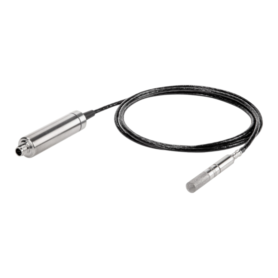
Page 8: Hmp4 Probe
32 mm 27 mm Figure 3 HMP4 Probe Dimensions Vaisala HUMICAPâ Humidity and Temperature Probe HMP4 is designed for high-pressure applications such as compressed air systems in maritime, breathing air, and industrial applications, where measurement performance and chemical tolerance are essential. -
Page 9: Hmp5 Probe
19 [0.75] [in] Figure 5 Optional Mounting Flange 210696 Dimensions Vaisala HUMICAPâ Humidity and Temperature Probe HMP5 is designed for high-temperature applications such as baking ovens, pasta dryers, and industrial drying kilns, where measurement performance and chemical tolerance are essential. • Temperature measurement range -70 ... +180 °C (-94 ... +356 °F) •... -
Page 10: Hmp7 Probe
Figure 6 HMP7 Probe Dimensions Vaisala HUMICAPâ Humidity and Temperature Probe HMP7 is designed for applications that involve constant high humidity or rapid changes in humidity, such as drying and test chambers, combustion air, and other humidifiers and meteorological measurements, where measurement performance and chemical tolerance are essential. -
Page 11: Hmp8 Probe
ISO1/2” or NPT1/2” Figure 7 HMP8 Probe Dimensions Vaisala HUMICAPâ Humidity and Temperature Probe HMP8 is designed for pressurized applications in compressed air systems, refrigerant dryers, and other pressurized industrial applications, where easy insertion and removal of the probe and adjustable installation depth into the pipeline are needed. -
Page 12: Attaching Ball Valve Kit To Process
Attaching Ball Valve Kit to Process G1/2 ISO 228/1 Ø14 Ø14 Ø14 Ø21.5 (drilling) Ball valve handle: must point to the same direction as the ball valve body when installing. Extension nipple, threads G1/2 ISO228/1 and R1/2 ISO7/1. Ball valve body. When tightening the assembly, turn only from the ball valve body. Ball of the ball valve. - Page 13 3. Tighten the ball valve assembly by turning from the ball valve body. CAUTION! Tightening the ball valve kit by turning the extension nipple can break the sealing. Tighten the ball valve assembly only from the ball valve body. 4. If you need to cap the ball valve assembly before installing or after removing the probe, attach a blanking nut to close the top of the valve.
-
Page 14: Hmp9 Probe
16 [0.63] point Figure 8 HMP9 Probe Dimensions Vaisala HUMICAPâ Humidity and Temperature Probe HMP9 is designed for easy installation into rapidly changing environments where fast response time, measurement performance, and chemical tolerance are essential. The probe head can be mounted through thin metal walls using the included cable gland or mounting grommet. -
Page 15: Installing Hmp9 Through A Cable Gland
Installing HMP9 Through a Cable Gland Figure 9 Installing HMP9 Probe Head Through a Cable Gland Black plastic part of the HMP9 probe head Nut for tightening the probe in place Base of the cable gland M10×1.5 threads of the cable gland •... -
Page 16: Tmp1 Probe
Probe cable 2 m [6.56 ft] 130 [5.12] Figure 10 TMP1 Probe Dimensions Vaisala Temperature Probe TMP1 is designed for demanding temperature measurements in industrial applications such as pharmaceutical industry and calibration laboratories, where accuracy and robustness are essential. • Temperature measurement range -70 ... +180 °C (-94 ... +356 °F) •... -
Page 17: Connector Pinout
Connector Pinout Figure 11 M12/5 Male Connector Pinout Pin # Function Notes Wire Colors in Vaisala Cables Power supply Supply voltage: Brown • HMP7: 18 ... 30 VDC • Other models: 15 ... 30 VDC Typical current 10 mA, max. 500 mA. -
Page 18: Attaching Probes To Indigo Transmitters
Attaching Probes to Indigo Transmitters Figure 13 Attaching the Probe to Indigo 200 Series 1. Insert the probe or the connection cable into the transmitter's connector. Use of connection cable is recommended for strain relief. 2. Turn the locking wheel of the transmitter to lock the probe or cable in place. Do not turn the probe or the cable itself, as that will damage the connectors. -
Page 19: Vaisala Insight Software
• Configure probe features such as measurement filtering, chemical purge, heating, and serial communication Download Vaisala Insight software at www.vaisala.com/insight. The probe can be connected to Vaisala Insight software using a Vaisala USB cable (no. 242659). Connecting to Insight Software •... -
Page 20: Modbus
Modbus address. Measurement Data Registers Measurement data is also available as integer registers if use of floating point is a problem for your implementation. See HMP Series User Guide (M212022EN) available at www.vaisala.com. Table 2 Floating Point Measurement Data Registers (Read-Only) Register... -
Page 21: Configuration Registers
32-bit float Configuration Registers The configuration registers listed here are the most important for typical users. For more information on available configuration registers, see HMP Series User Guide (M212022EN) available at www.vaisala.com. Table 3 Modbus Configuration Data Registers (Writable) Register Register... -
Page 22: Test Value Registers
Compensation Setpoints 0334 Temperature 32-bit float Unit: °C compensation setpoint. If a value is written to this register, probe uses it when calculating relative humidity instead of its own measurement. When probe heating is in use, temperature must be written to this register to enable relative humidity measurement. -
Page 23: Technical Support
Technical Support Contact Vaisala technical support at helpdesk@vaisala.com. Provide at least the following supporting information: • Product name, model, and serial number • Name and location of the installation site • Name and contact information of a technical person who can provide further information on the problem For more information, see www.vaisala.com/support. - Page 24 M211982EN-D...
- Page 25 目次 製品概要....................26 プローブ構造....................26 基本機能とオプション..................26 取り付け....................27 HMP4 プローブ.................. 28 HMP5 プローブ.................. 29 HMP7 プローブ.................. 30 HMP8 プローブ.................. 31 プロセスへのボールバルブキットの取り付け..........32 HMP9 プローブ.................. 34 ケーブルグランドからの HMP9 の取り付け.............35 TMP1 プローブ.................. 36 コネクターのピン配列................. 37 プローブの Indigo 変換器への取り付け..........38 Vaisala Insight ソフトウェア...............39 Insight ソフトウェアへの接続................. 39 Modbus......................40 通信の初期設定....................40...
-
Page 26: 製品概要
製品概要 HMP シリーズプローブは 、デジタル出力(Modbus プロトコル)の湿度・温度計測プロー ブです。 これらのプローブは厳しい環境下における湿度と温度の計測用に設計されていま す。 いずれのプローブモデルもプローブ 本体とプローブヘッド間を接続する 2 m(6.5 ft) のケーブルが付属しています。 これらのプローブは、 ヴァイサラ Indigo 変換器と互換性があります。 また、 Vaisala Insight ソフトウェアに接続して、設定、診断、および一時オンラインモニタリングを行えます。 プローブ構造 図 15 プローブの部品 保護キャップ(使用前に取り外す) 5 ピン M12 コネクター プローブ本体(タイプラベル付き) 状態インジケーター: 緑 電源がオンでプローブがオン ライン、通信時は点滅 赤 エラー オフ 電源がオフ、またはインジ ケーターが無効... -
Page 27: 取り付け
取り付け プローブの取り付け場所を選択する際には、以下のことを考慮してください。 • プローブモデルの使用環境仕様を確認します。 一般的に、プローブヘッドの方がプ ローブ本体よりも動作温度範囲がかなり広くなっています。 • 計測環境の温度が周囲温度と大きく異なる場合は、プローブヘッド全体とケーブルを なるべく長く計測環境内に入れてください。 これにより、ケーブルの熱伝導による計 測誤差を防ぐことができます。 • プローブの取り付けオプションはモデルごとに異なります。 図 16 HMP8 モデルの取り付け例 プローブヘッドに結露した水がセンサに流れるのを防止するため、 プローブヘッドを水 平に取り付けます。 結露した水がケーブルを伝わってプローブヘッドに 流れるのを防止するため、 ケーブル をゆるく吊します。 プローブに付属の 2 つの取り付けクリップ(ヴァイサラ部品:243257SP)を使用して、 プローブ本体を壁や他の表面に取り付けます。 クリップはそれぞれ、ネジ 1 本(ネジ 穴 Ø 4.2 mm)を使用して取り付け面に取り付けます。 Modbus マスターまたは Indigo 変換器にケーブルを接続します。... -
Page 28: Hmp4 プローブ
HMP4 プローブ M12/5 プローブケーブル 2 m フィッティングボディ M22x1.5 または NPT1/2” 32 mm 27 mm 図 17 HMP4 プローブの寸法 ヴァイサラ HUMICAPâHMP4 湿度温度プローブは、計測性能と多くの化学物質への耐性が あります。船舶、ブリージングエア、工業利用などにおける圧縮空気システムの高圧用途 向けに設計されています。 • 温度測定範囲:-70~ +180 °C(-94~ +356 °F) • 動作圧力:0~ 10 MPa(0~100 bar) • プローブ本体の動作温度範囲:-40~+80 °C(-40~ +176 °F) • M22x1.5 および NPT1/2 インチプローブフィッティングが 付属... -
Page 29: Hmp5 プローブ
HMP5 プローブ M12/5 プローブケーブル 2 m 図 18 HMP5 プローブの寸法 図 19 オプションの取り付けフランジ 210696 寸法 ヴァイサラ HUMICAPâHMP5 湿度温度プローブは、計測性能と多くの化学物質への耐性が あります。ベーキングオーブン、パスタ乾燥機、工業用乾燥炉などの高温環境用途向けに 設計されています。 • 温度計測範囲:-70~+180 °C(-94~+356 °F) • プローブ本体の動作温度範囲:-40~+80 °C(-40~+176 °F) • 250 mm(9.84 in)プローブにより、壁面を貫通しての取り付けが容易 • ステンレス焼結フィルターが標準付属... -
Page 30: Hmp7 プローブ
HMP7 プローブ M12/5 プローブケーブル 2 m 99.5 79.5 37.5 ロックリング の溝 図 20 HMP7 プローブの寸法 ヴァイサラ HUMICAPâHMP7 湿度温度プローブは、計測性能と多くの化学物質への耐性が あります。乾燥室やテストチャンバー、空調用空気、その他の環境試験器や気象計測器な どの常時高湿度または急速な湿度変化が伴う用途向けに設計されています。 • 温度測定範囲:-70~ +180 °C(-94~+356 °F) • プローブ本体の動作温度範囲:-40~+80 °C(-40~+176 °F) • プローブ上の結露を最小限に抑える加温機能 • 耐圧気密構造 • ステンレスネット付金属化 PPS プラスチックグリッドが標準付属 プローブ加温 HMP7 はプローブ加温の機能を持っています。 加温プローブは、センサーだけでなく、プ ローブヘッド全体が加温されます。... -
Page 31: Hmp8 プローブ
HMP8 プローブ M12/5 プローブケーブル 2 m 41 ... 149 フィッティングボディ ISO1/2” または NPT1/2” 図 21 HMP8 プローブの寸法 ヴァイサラ HUMICAPâHMP8 湿度温度プローブは、プローブの挿入や取り外しが容易で、 パイプラインへの挿入長の調整が求められる、圧縮空気システム、冷凍式エアドライヤ、 環境チャンバーなどの圧力下用途向けに設計されています。 • 温度計測範囲:-70~+180 °C(-94~+356 °F) • プローブ本体の動作温度範囲:-40~+80 °C(-40~+176 °F) • 動作圧力:0~4 MPa(0~40 bar) • プローブは、挿入長を自由に調整でき、オプションのボールバルブを使用すれば、シ ステムを停止せずに高圧パイプラインからの取り外しが可能 • ISO 1/2 インチあるいは NPT1/2 インチプローブフィッティングとプレスハンドルが 付属... -
Page 32: プロセスへのボールバルブキットの取り付け
プロセスへのボールバルブキットの取り付け G1/2 ISO 228/1 Ø14 Ø14 Ø14 Ø21.5(ドリリング) ボールバルブハンドル: 取り付け時には、ボールバルブ本体と同じ向きを指している 必要があります。 延長ニップル、ネジ 1/2 ISO228/1 および R1/2 ISO7/1。 ボールバルブ本体。 アセンブリを締め付けるときには、ボールバルブ本体側からのみ 回してください。 ボールバルブのボール。 溶接ジョイント、ネジ R1/2 ISO7/1。 1. 溶接ジョイントをプロセスパイプまたはチャンバーに取り付けます。 M211982EN-D... - Page 33 2. シーラント(MEGA-PIPE EXTRA No 7188 または LOCTITEâ No 542 +activ. No 7649) を溶接ジョイントのネジ部に塗布し、ボールバルブの基部を溶接ジョイントにねじ込 みます。 3. ボールバルブ本体側から回し、ボールバルブアセンブリを締め付けます。 注意 延長ニップルを回してボールバルブキットを締め付けると、シーリ ング材が破損することがあります。 ボールバルブアセンブリを締め付け るときには、ボールバルブ本体側からのみ回してください。 4. プローブを取り付ける前または取り外した後にボールバルブアセンブリにキャップを 取り付ける必要がある場合、ブランクナットを取り付けてバルブの上部を閉じてくだ さい。...
-
Page 34: Hmp9 プローブ
HMP9 プローブ 112 [4.41] [in] M12/5 プローブケーブル 2m [6.56 ft] 94 [3.70] 取り付けポイント 16 [0.63] 図 22 HMP9 プローブの寸法 ヴァイサラ HUMICAPâ HMP9 湿度温度プローブは、高速な応答時間、測定性能、耐薬品性 が不可欠な変化の速い環境に、簡単に取り付けられるように設計されています。 プローブヘッドは、付属のケーブルグランドまたは取り付けグロメットを使用して、金属 製の薄い壁を通して取り付けることができます。 ジップタイを使用してプローブヘッドを 直接取り付けることもできます。 プローブヘッドは、黒色のプラスチック部分付近のポイ ントから取り付ける必要があります。 • 温度計測範囲:-40~+120°C(-40~+248°F) • プローブ本体の動作温度範囲:-40~+60°C(-40~+140°F) • 統合型フィルター(交換不可) 注意 プローブヘッドを曲げたり、潰したり、叩いたりして、損傷しないよう にしてください。 プローブヘッドをケーブルグランドから 取り付けるときに 締め付けすぎないようにしてください。... -
Page 35: ケーブルグランドからの Hmp9 の取り付け
ケーブルグランドからの HMP9 の取り付け 図 23 ケーブルグランドからの HMP9 プローブヘッドの取り付け HMP9 プローブヘッドの黒色のプラスチック部分 プローブを所定の位置に固定するためのナット ケーブルグランドの基部 ケーブルグランドの M10×1.5 ネジ • M10×1.5 ケーブルグランド(HMP9 プローブに付属) • ドリルと 8.5 mm ビット • M10×1.5 ねじ切りタップ • 13 mm レンチ 1. 取り付け位置に直径 8.5 mm の穴を開けます。 2. ねじ切りタップを使用して、穴に M10×1.5 のネジ山を付けます。 3. ケーブルグランドの基部を穴に取り付け、13 mm レンチで締め付けます。 4. -
Page 36: Tmp1 プローブ
TMP1 プローブ M12/5 プローブケーブル 2 m 図 24 TMP1 プローブの寸法 ヴァイサラ TMP1 温度プローブは、精度や堅牢性が不可欠な製薬業界や校正試験所など、 温度計測に厳しい要件が求められる産業用途向けに設計されています。 • 温度測定範囲:-70~ +180 °C(-94~ +356 °F) • プローブ本体の動作温度範囲:-40~+80 °C(-40~ +176 °F) M211982EN-D... -
Page 37: コネクターのピン配列
コネクターのピン配列 図 25 M12/5 オスコネクターのピン配列 ピン番 機能 備考 ヴァイサラケーブルの線の 号 色 電源 電源電圧: 茶色 • HMP7: 18 ... 30 VDC • その他のモデル: 15 ... 30 VDC 電流は標準 10 mA、最大 500 mA。 RS-485 - 白色 電源 GND および 青色 RS-485 コモン RS-485 + 黒色... -
Page 38: プローブの Indigo 変換器への取り付け
プローブの Indigo 変換器への取り付け 図 27 プローブの Indigo 200 シリーズへの取り付け 1. プローブまたは接続ケーブルを変換器のコネクタに挿入します。負荷を緩和するため に、接続ケーブルの使用をお勧めします。 2. 変換器の固定用ホイールを回して、プローブまたはケーブルを 所定の位置に固定しま す。コネクタが損傷するため、プローブまたはケーブル 自体をつかんで回さないでく ださい。 3. 接続ケーブルを使用する場合、プローブをケーブルに 接続します。 4. 変換器で接続したプローブが認識されると、ディスプレイに通知メッセージが表示さ れます。 M211982EN-D... -
Page 39: Vaisala Insight ソフトウェア
• プローブの校正と調整 • 計測フィルタリング、ケミカルパージ、加温、シリアル通信などのプローブ機能の設 定 Vaisala Insight ソフトウェアは、www.vaisala.com/insight からダウンロードしてくださ い。 プローブは、ヴァイサラ USB ケーブル(注文コード 242659)を使用して、Vaisala Insight ソフトウェアに接続できます。 Insight ソフトウェアへの接続 • Vaisala Insight ソフトウェアをインストールしたコンピューター • USB 接続ケーブル(注文コード 242659) 図 28 プローブの Insight への接続 1. Insight ソフトウェアを開きます。 2. USB ケーブルを PC の空いている USB ポートに接続します。... -
Page 40: Modbus
19200 パリティ なし データビット数 ストップビット数 フロー制御 なし Modbus デバイスアドレス 同じ RS-485 ラインで最大 10 台のプローブを使用できます。 ライン上のプローブごとに 異なる Modbus アドレスを設定する必要があります。 計測データレジスター 実装環境で浮動小数点を使用すると問題が発生する場合は、測定データを整数レジスター として利用することもできます。 www.vaisala.com で提供されている『HMP シリーズ ユーザーガイド』 (M212022EN)を参照してください。 表 6 浮動小数点計測データレジスター(読み取り専用) レジスター番号 アドレス (16 進 レジスターの説明 データ形式 メートル系単位 (10 進数) 数) 0000 相対湿度... -
Page 41: 設定レジスター
32 ビット浮動 °C 小数点 0020 NTP における絶対湿度 32 ビット浮動 小数点 0040 水分質量分率 32 ビット浮動 小数点 設定レジスター ここに一覧表示されている設定レジスターは、一般的なユーザーにとって 最も重要なレジ スターです。 利用可能な設定レジスターの詳細については、www.vaisala.com で提供され ている『HMP シリーズユーザーガイド』 (M212022EN)を参照してください。 表 7 Modbus 設定データレジスター(書き込み可能) レジスター レジスター レジスターの説明 データ形式 単位/有効範囲 番号(10 進 アドレス 数) (16 進数) 全般 1289 0508 プローブ加温のオン/オ... -
Page 42: テスト値レジスター
補正設定値 0334 温度補正設定値。 値がこ 32 ビット浮 単位: °C のレジスターに書き込ま 動小数点 れている場合、 プローブは 相対湿度を計算する際に 自身の計測値の代わりに レジスターの値を使用し ます。 プローブ加温を使用して いる場合、 温度をこのレジ スターに書き込んで、 相対 湿度計測を有効にする必 要があります。 通信 1537 0600 Modbus アドレス 16 ビット整 1 ... 247 数 初期設定: 240 テスト値レジスター テストレジスターから既知のテスト値を読み込み、Modbus 実装環境が機能するかどうか 確認できます。 表... -
Page 43: 技術サポート
技術サポート ヴァイサラ社技術サポート(helpdesk@vaisala.com)までお問い合わせくだ さい。最低限、サポートに必要な以下の情報をご提供ください。 • 製品の名前、モデル、シリアル番号 • 設置サイトの名前と場所 • 問題に関する詳細情報をご提供いただける技術担当者様の氏名および連絡 先情報 詳細については、www.vaisala.com/support を参照してください。 詳細 プローブの取り付け、設定、およびメンテナンスについては、www.vaisala.com で提供さ れている『HMP シリーズユーザーガイド』 (M212022EN)を参照してください。 保証 標準的な保証条件については、www.vaisala.com/warranty を参照してください。 通常の損耗、特別な環境における使用、不注意な使い方またはインストール、もしく認証 されていない改造による損傷に対しては、上記保証は無効となります。各製品の保証の詳 細については、適用される供給契約または販売条件を参照してください。 リサイクル リサイクル可能な材料は、すべてリサイクルしてください 。 製品および梱包は、法定規則に従って廃棄してください。... - Page 44 M211982EN-D...
-
Page 45: Regulatory Compliances
Regulatory Compliances FCC Part 15 Compliance Statement This equipment has been tested and found to comply with the limits for a Class B digital device, pursuant to Part 15 of the FCC rules. These limits are designed to provide reasonable protection against harmful interference in a residential installation. - Page 47 www. v aisala.com...
Need help?
Do you have a question about the HMP4 and is the answer not in the manual?
Questions and answers