Table of Contents
Advertisement
Quick Links
Advertisement
Table of Contents

Related Manuals for Barco BlendPRO-II


Summary of Contents for Barco BlendPRO-II
- Page 1 _äÉåÇmolJff rëÉêÛë=dìáÇÉ • Manual # 26-0507000-00 • Revision A...
- Page 2 30 days after the transfer of risks. In the event of justified notice of compliant, Barco can repair the fault or provide a replacement at its own discretion within an appropriate period. If this measure proves to be impossible or unsuccessful, the purchaser can demand a reduction in the purchase price or cancellation of the contract.
- Page 3 Not included in the guarantee coverage are system failures which are attributed to programs or special electronic circuitry provided by the purchaser, e.g. interfaces. Normal wear as well as normal maintenance are not subject to the guarantee provided by Barco either.
- Page 4 Use only the power cord and connector specified for your product. Use only a power cord that is in good condition. Refer cord and connector changes to qualified service personnel. aç=kçí=léÉê~íÉ=áå=bñéäçëáîÉ=^íãçëéÜÉêÉë To avoid explosion, do not operate this product in an explosive atmosphere. BlendPRO-II • User’s Guide...
- Page 5 Ein Ausrufungszeichen innerhalb eines gleichwinkeligen Dreiecks dient dazu, den Benutzer auf wichtige Bedienungs-und Wartungsanweisungen in der Dem Great beiliegenden Literatur aufmerksam zu machen. BlendPRO-II • User’s Guide...
- Page 6 `Ü~åÖÉ=eáëíçêó The table below lists the changes to the BlendPRO-II User’s Guide. Table 0-1. Change History Date ECO # Description Approved By 8/7/06 1674 BlendPRO-II User’s Guide M. Lettau BlendPRO-II • User’s Guide...
-
Page 7: Table Of Contents
BlendPRO-II Front Panel ........ - Page 8 Contact Information ..........42 fåÇÉñ =K=K=K=K=K=K=K=K=K=K=K=K=K=K=K=K=K=K=K=K=K=K=K=K=K=K=K=K=K=K=K=K=K=K=K=K=K=K=K=K=K=K=K=K=K=K=K=K=K=K=K=K=K=QP BlendPRO-II • User’s Guide...
-
Page 9: Chapter Structure
NK==fåíêçÇìÅíáçå få=qÜáë=`Ü~éíÉê This chapter is designed to introduce you to the BlendPRO-II User’s Guide. Areas to be covered are: • Chapter Structure • How to Use This Guide • Conventions • About the BlendPRO-II • Features • Application Questions •... - Page 10 NK==fåíêçÇìÅíáçå Chapter Structure `Ü~éíÉê=píêìÅíìêÉ The following chapters provide instructions for all aspects of BlendPRO-II operations: • Chapter 1, “Introduction” provides a system overview, a list of features, and a system connectivity diagram. • Chapter 2, “Hardware Orientation” on page 15 provides detailed diagrams of the system’s front and rear panels.
- Page 11 The following conventions are used throughout this guide: • The symbol denotes an operations procedure. • The symbol denotes an example. • Entries written in bold-face capital letters denote physical buttons or chassis connectors. Use the GENLOCK connector to ... BlendPRO-II • User’s Guide...
- Page 12 The system completely eliminates the need to “pre-overlap” source material during the content creation phase of your presentation. BlendPRO-II receives signals from up to four ScreenPro-II units (via high-resolution DVI connections) and processes the video for display in multi-projector widescreen format.
-
Page 13: Features
ScreenPRO-II Controller. ^ééäáÅ~íáçå=nìÉëíáçåë At Barco, we take pride in offering unique solutions to demanding technical problems. If you have application questions, require further information or would like to discuss your application requirements in more detail, please call (916) 859-2500. Our Customer Support Engineers will be happy to supply you with the support you need. -
Page 14: Connectivity Diagram
DVI signals connect the ScreenPRO-II outputs to BlendPRO-II, and the BlendPRO-II to each projector input. • Analog connectivity from each ScreenPRO-II is used for monitoring. • The Widescreen Lock output from BlendPRO-II is used to lock each ScreenPRO-II system. These connections are required. BlendPRO-II • User’s Guide... -
Page 15: Blendpro-Ii Front Panel
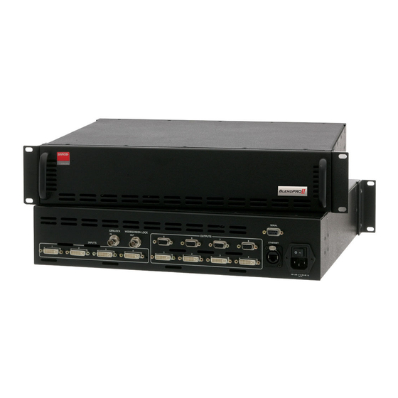
OK==e~êÇï~êÉ=lêáÉåí~íáçå få=qÜáë=`Ü~éíÉê This chapter provides detailed diagrams of the system’s front and rear panels. The following topics are discussed: • BlendPRO-II Front Panel • BlendPRO-II Rear Panel BlendPRO-II • User’s Guide... - Page 16 PRO II LEND Figure 2-1. BlendPRO-II Front Panel There are no user controls on the front panel of the BlendPRO-II chassis. All operating procedures are performed through the ScreenPRO-II Controller. Refer to Chapter 4, “Operation” on page 29 for additional details.
- Page 17 Genlock In One BNC connector is provided for a Genlock Input, which can be used to lock BlendPRO-II and its associated ScreenPro-II inputs to an external source if desired. Please note: BlendPRO-II can genlock to Composite bi or tri-level syncs.
- Page 18 One 9-pin D connector is provided for RS-232 serial communications with BlendPRO-II, typically for diagnostic purposes. The port is configured as a DCE, 115K Baud, 8 data bit, 1 stop bit, and no parity bits. The port can be connected to a standard PC serial port with a straight through DB-9 to DB-9 cable.
- Page 19 37 for pinout details. Ethernet Port One RJ-45 (Neutrik) connector is provided for Ethernet communications with BlendPRO-II. Ethernet is the primary means of controlling the BlendPRO-II. Please note: The Ethernet port is 10/100 Mbit auto-sensing capable. The port is primarily configured to run as a DHCP client, although static IP can be used if desired.
- Page 20 2. Hardware Orientation BlendPRO-II Rear Panel BlendPRO-II • User’s Guide...
-
Page 21: Safety Precautions
PK==fåëí~ää~íáçå få=qÜáë=`Ü~éíÉê This chapter provides detailed instructions for installing the BlendPRO-II hardware. The following topics are discussed: • Safety Precautions • Unpacking and Inspection • Site Preparation • Cable and Adapter Information • Rack-Mount Installation • Power Installation • Signal Installation •... - Page 22 Before opening the BlendPRO-II box, inspect it for damage. If you find any damage, notify the shipping carrier immediately for all claims adjustments. As you open the box, compare its contents against the packing slip. If you find any shortages, contact your Barco sales representative.
- Page 23 3. Installation Rack-Mount Installation o~ÅâJjçìåí=fåëí~ää~íáçå BlendPRO-II units are designed to be rack mounted and are supplied with front rack-mount hardware. Please note the following important points: • Rear rack-mount brackets are available as a kit, and are recommended for use when units are mounted in transit cases.
-
Page 24: Power Installation
Input Power: 100-240 VAC, 47-63 Hz • Power Consumption: 80 watts maximum BlendPRO-II performs line voltage selection automatically, and no user controls are required. The AC power cords must be accessible so that they can be removed during field servicing. -
Page 25: Signal Installation
3. Installation Signal Installation páÖå~ä=fåëí~ää~íáçå The figure below illustrates a sample BlendPRO-II system, which uses the maximum four ScreenPRO-II units. Use this figure for reference during the signal installation process. If required, refer to the “BlendPRO-II Rear Panel” section on page 17 in Chapter 2 for details on all rear panel connectors. - Page 26 Connect a DVI output from each ScreenPRO-II unit (up to the maximum of 4) to the DVI inputs on BlendPRO-II. Connect the DVI or analog outputs from BlendPRO-II to the inputs of your selected projectors (up to the maximum of 4). If you are using the analog outputs, refer to the “Format Connection...
- Page 27 If a particular ScreenPRO-II chassis is the last device in a reference video chain, ensure that the Termination Switch is pushed in. If a particular ScreenPRO-II chassis is in the middle of a reference chain, ensure that the Termination Switch is out. BlendPRO-II • User’s Guide...
-
Page 28: Format Connection Table
Format Connection Table cçêã~í=`çååÉÅíáçå=q~ÄäÉ Use the following table to connect BlendPRO-II’s analog RGB output to various analog projector inputs (3 wire, 4 wire and 5 wire). Using a customer supplied VGA to 5 x BNC breakout cable, multiple combinations are possible. Cells with checks denote the connections required for the indicated format. -
Page 29: Control Overview
QK==léÉê~íáçå få=qÜáë=`Ü~éíÉê This chapter provides detailed operating instructions for the BlendPRO-II. The following topics are discussed: • Control Overview BlendPRO-II • User’s Guide... - Page 30 4. Operation Control Overview `çåíêçä=lîÉêîáÉï All BlendPRO-II setup and operating procedures are performed through the ScreenPRO-II Controller. There are no user controls on the BlendPRO-II unit itself. Important Refer to the “ScreenPRO-II Controller User’s Guide” for complete setup and operating procedures.
-
Page 31: Software Upgrade Overview
RK==réÖê~ÇáåÖ=pçÑíï~êÉ få=qÜáë=`Ü~éíÉê This chapter provides instructions for upgrading BlendPRO-II system software. The following topics are discussed: • Software Upgrade Overview BlendPRO-II • User’s Guide... - Page 32 If the ScreenPRO-II Controller’s code version matches that of the ScreenPRO-II units and BlendPRO-II, the Controller’s System Status Menu is shown — and you will not need to download code. If the message “Checksum Mismatch” appears on the System Status Menu, you must download code.
-
Page 33: Input Specifications
^K==péÉÅáÑáÅ~íáçåë få=qÜáë=^ééÉåÇáñ This appendix provides detailed technical specifications for the BlendPRO-II. The following topics are discussed: • Input Specifications • Output Specifications • User Control Specifications • Physical and Electrical Specifications • Communications Specifications • Agency Specifications • Pinouts BlendPRO-II • User’s Guide... - Page 34 ^K==péÉÅáÑáÅ~íáçåë Input Specifications fåéìí=péÉÅáÑáÅ~íáçåë= The table below lists BlendPRO-II input specifications. Table A-1. BlendPRO-II Input Specifications Parameter Detail Specification DVI Inputs 1 - 4 Connector (4) DVI-D connectors (digital, single link, receptacle), each input per DDWG 1.0 specifications. Video Progressive RGB...
- Page 35 No local controls provided. Setup All setup functions performed from ScreenPRO-II Controller. Remote control All control functions performed from ScreenPRO-II Controller. mÜóëáÅ~ä=~åÇ=bäÉÅíêáÅ~ä=péÉÅáÑáÅ~íáçåë= The table below lists BlendPRO-II physical and electrical specifications. Table A-4. BlendPRO-II Physical and Electrical Specifications Parameter Detail Specification Power...
-
Page 36: Communications Specifications
^K==péÉÅáÑáÅ~íáçåë Communications Specifications `çããìåáÅ~íáçåë=péÉÅáÑáÅ~íáçåë= The table below lists BlendPRO-II communications specifications. Table A-5. BlendPRO-II Communications Specifications Parameter Detail Specification Communications RS-232 DB-9 Female, DCE, 115k Baud Ethernet RJ-45, 10/100 Mbps Autosense ^ÖÉåÅó=péÉÅáÑáÅ~íáçåë= The table below lists BlendPRO-II agency specifications. Table A-6. BlendPRO-II Agency Specifications... -
Page 37: Pinouts
Figure A-1. Analog 15-pin D Connector, chassis view The table below lists Analog 15-pin D connector pinouts. Table A-7. Analog 15-pin D Connector Pinouts Signal Signal Green Blue H Sync or C Sync Red return V Sync Green return Blue return BlendPRO-II • User’s Guide... - Page 38 T.M.D.S. Data 0+ DDC Data T.M.D.S. Data 0/5 Shield T.M.D.S. Data 5- T.M.D.S. Data 1- T.M.D.S. Data 5+ T.M.D.S. Data 1+ T.M.D.S. Clock Shield T.M.D.S. Data 1/3 Shield T.M.D.S. Clock + T.M.D.S. Data 3- T.M.D.S. Clock - BlendPRO-II • User’s Guide...
- Page 39 Table A-9. Ethernet Connector Pinouts Signal Wire Color TX Data + White / Orange TX Data - Orange RX Data + White / Green Blue White / Blue RX Data - Green White / Brown Brown BlendPRO-II • User’s Guide...
- Page 40 The table below lists Serial connector pinouts. Table A-10. Serial Connector Pinouts RS-232 Signal Description Carrier Detect Received Data Transmitted Data Data Terminal Ready Signal Ground Data Set Ready Request To Send Clear To Send Unused BlendPRO-II • User’s Guide...
-
Page 41: In This Appendix
Warranty related repairs include parts and labor, but do not include faults resulting from user negligence, special modifications, lightning strikes, abuse (drop/crush), and/or other unusual damages. The customer shall pay shipping charges when unit is returned for repair. Barco will cover shipping charges for return shipments to customers. oÉíìêå=j~íÉêá~ä=^ìíÜçêáò~íáçå=Eoj^F... -
Page 42: Contact Information
Noordlaan 5 8520 Kuurne BELGIUM • Phone: +32 56.36.82.11 • Fax: +32 56.35.16.51 • Website: www.barco.com Technical Support Information • Tech Line: (866) 374-7878 — 24 hours per day, 7 days per week • E-mail: folsomsupport@barco.com BlendPRO-II • User’s Guide... - Page 43 About BlendPRO-II .....12 Cable information ..... .22 Change history .
- Page 44 FCC statement ......2 Features, BlendPRO-II ....13 Front panel connectors .
- Page 45 User control specifications ....35 Warranty ......41 BlendPRO-II • User’s Guide...
- Page 46 Index BlendPRO-II • User’s Guide...
Need help?
Do you have a question about the BlendPRO-II and is the answer not in the manual?
Questions and answers