Vinotemp WINE-MATE WM-1500HTD Installation, Use & Care Manual
Hide thumbs
Also See for WINE-MATE WM-1500HTD:
- Installation, use & care manual (25 pages) ,
- Use & care manual (21 pages) ,
- Installation manual (10 pages)
Table of Contents
Advertisement
Quick Links
Advertisement
Table of Contents

Subscribe to Our Youtube Channel
Related Manuals for Vinotemp WINE-MATE WM-1500HTD


Summary of Contents for Vinotemp WINE-MATE WM-1500HTD
- Page 1 Wine Cooling System WM-1500HTD WM-1500HTD-TE WM-2500HTD WM-2500HTD-TE Installation, Use & Care Manual Read and save these instructions...
-
Page 2: Important Safety Information
Important Safety Information • DO NOT PLUG IN UNTIL 24 HOURS AFTER DELIVERY. • DO NOT USE A GROUND FAULT INTERRUPTER (GFI). • A DEDICATED 20 AMP CIRCUIT IS REQUIRED. - 1 -... -
Page 3: Table Of Contents
Table of Contents Features & Specifications.…………………….……………..3 Installation Instructions..……………………………………..5 Temperature and Humidity……………..…………………..12 Care Guide…………………………………………..………16 Troubleshooting……………………………………………..17 Wiring Diagram……………………………………….………20 Customer Support……………………………………………22 Warranty……………………………………………………….23 - 2 -... -
Page 4: Features & Specifications
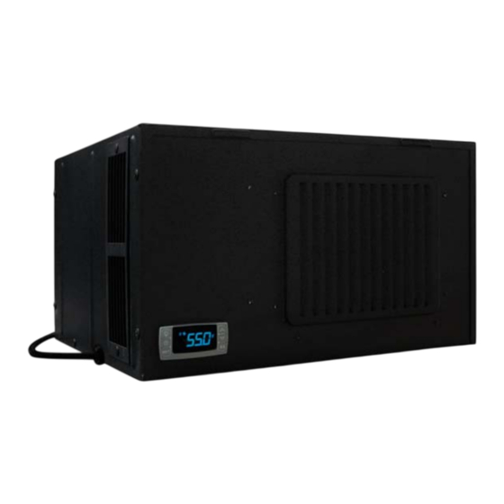
Features and Specifications • WM-1500HTD, HTD-TE and WM-2500HTD, HTD-TE cooling units are designed and used to provide a subtle temperature between 50~65 °F for a properly insulated wine cabinet. • The refrigerated space will maintain humidity range within 50~70% RH. •... - Page 5 Fig. 1.2 DIMENSIONS (in) The specifications and dimensions are listed as follows: Cabinet Size Model Exhaust Electrical Weight (lb) (cu ft) Rear Exhaust 115V/60Hz/4A 1500htd Top Exhaust 115V/60Hz/4A 1500htd-te Rear Exhaust 115V/60Hz/5A 2500htd Top Exhaust 115V/60Hz/5A 2500htd-te NOTES: • Also see the voltage, frequency and current specified on the label at the cooling unit.
-
Page 6: Installation Instructions
Installation Instructions NOTES: • Mounting brackets, screws, gaskets and other seal materials are not included. • Do not install any ducts onto the supply, return, intake and exhaust. • Because of potential safety hazards under a certain condition, we strongly recommend against the use of an extension cord. - Page 7 ambient-air intake and hot-air exhaust must not be short-circulated. A piece of wood may be used to separate them. • Cut a rectangular inside opening at the rear of the cabinet with the 1/4” clearance inwards to the width and height of the cooling unit. By not going through, leave 1/2”...
- Page 8 Fig. 2.1 CUTOUT AND HOLE DIMENSIONS Fig. 2.2 REAR EXHAUST CUTOUT - 7 -...
- Page 9 Fig. 2.3 TOP EXHAUST CUTOUT Fig. 2.4 MOUNTING SCREW INSERT Fig. 2.5 REAR GASKET - 8 -...
- Page 10 Fig. 2.6 TOP EXHAUST GASKET - 9 -...
- Page 11 Fig. 2.7 COOLING UNIT MOUNTED - 10 -...
- Page 12 Fig. 2.8 COOLING UNIT MOUNTED (REAR EXHAUST) Fig. 2.9 COOLING UNIT MOUNTED (TOP EXHAUST) - 11 -...
-
Page 13: Temperature And Humidity
Temperature and Humidity 1. Use of the controller Fig. 3.1 TEMPERATURE CONTROLLER 1) Keys SET: To display target set point; in programming mode it selects a parameter or confirm an operation. (DEF): To start a manual defrost. (UP): To see the maximum stored temperature; in programming mode it browses the parameter codes or increases the displayed value. - Page 14 4) Alarm Signals The alarm codes are described as follows. MESSAGE CAUSE FUNCTION Temperature probe faulty Compressor switching to Con and CoF Probe temperature ALU higher than the High temperature alarm setting temperature; Outputs unchanged Probe temperature ALL lower than the Low temperature alarm setting temperature;...
- Page 15 5. How to calibrate the air probe If the actual cellar temperature differs from the displayed temperature, set ot = actual cellar temperature minus displayed temperature. 6. How to adjust defrost cycle In case the cooling unit does not stop, the parameters FnC = C-n, idF =4 and MdF = 30 can be used to cycle off.
- Page 16 3) Press up/down keys to scroll to the required parameter within 10 sec. 4) Press the “SET” key to display its value. 5) Use up/down keys to change its value within 10 sec. 6) Press “SET” to store the new value. 7) To exit: Press SET + or wait 15sec without pressing a key.
-
Page 17: Care Guide
Care Guide 1. Cleaning Condenser • Clean the condenser regularly at least every 6 months. • Condenser is located on the ambient air intake side of the cooling unit. • Use a condenser brush or a vacuum cleaner with an extended attachment to clean the condenser. -
Page 18: Troubleshooting
Troubleshooting This Troubleshooting Chart is not prepared to replace the training required for a professional refrigeration service person, not is it comprehensive Complaint Possible Causes Response a. Power cord not plugged a. Check power cord 1. Unit not b. No power from supply b. - Page 19 high or not seal opening b. Cabinet too large b. Check for excessive size cooling and c. Ambient temperature too high c. Check installation location running d. Exhaust restricted d. Leave minimum clearance for the continually hot air exhaust and fresh air intake sides e.
- Page 20 d. Temperature controller fault d. Change a new one a. Evaporator air flow restriction a. Check for fans and CFM 13.Evaporator b. Condenser air flow restriction b. Check for fans and CFM freezing up c. Not stopping due to air leak, high c.
-
Page 21: Wiring Diagram
Wiring Diagram Fig. 6.1 WIRING DIAGRAM - 20 -... - Page 22 Fig. 6.2 WIRING DIAGRAM (ALARM CALL) - 21 -...
-
Page 23: Customer Support
Customer Support If you need further assistance, please contact us at: Vinotemp International 17631 South Susana Road Rancho Dominguez, CA 90221 Tel: (310) 886-3332 Fax: (310) 886-3310 Email: info@vinotemp.com - 22 -... -
Page 24: Warranty
BTU/H. While every effort has been made to provide accurate guidelines, VINOTEMP can not warranty its units to cool a particular enclosure. In case of failure, VINOTEMP cooling units must be repaired by the factory or its authorized agent. Repairs or modifications made by anyone else will void the warranty. - Page 25 VINOTEMP will, at its discretion, repair or replace the unit and return it free of charge to the original retail customer. If the unit is found to be in good working order, or beyond the initial twelve month period, it will be returned freight collect.
Need help?
Do you have a question about the WINE-MATE WM-1500HTD and is the answer not in the manual?
Questions and answers