
Related Manuals for IMC Networks IE-MiniFiberLinX-II


Summary of Contents for IMC Networks IE-MiniFiberLinX-II
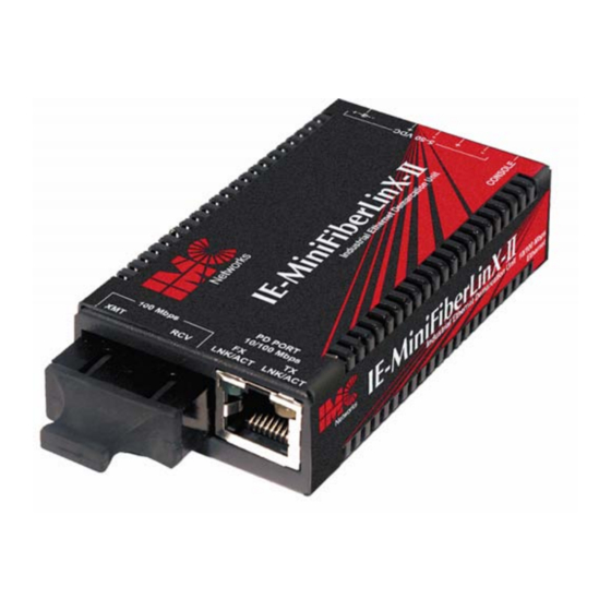
- Page 1 IE-MiniFiberLinX-II (Non-Telco, Telco and Telco/Last Gasp) Operation Manual Above illustrations are representative; some minor differences may be present in actual product...
-
Page 2: Fcc Radio Frequency Interference Statement
At its option, IMC Networks will repair or replace at no charge the product which proves to be defective within such warranty period. This limited warranty shall not apply if the IMC Networks product has been damaged by unreasonable use, accident, negligence, service or modification by anyone other than an authorized IMC Networks Service Technician or by any other causes unrelated to defective materials or workmanship. -
Page 3: Table Of Contents
Table of Contents FCC Radio Frequency Interference Statement ............ii Warranty......................ii About the IE-MiniFiberLinX-II Non-Telco, Telco and with Telco/Last Gasp..1 iView² Management Software ................2 Installation ......................3 DIN Rail Mounting.....................3 Mini-Serial Port ....................3 LED Operation....................4 Powering Options ....................4 Features and Configuration ................5 Auto Negotiation, Duplex Mode and Speed............5... -
Page 4: About The Ie-Minifiberlinx-Ii Non-Telco, Telco And With Telco/Last Gasp
Management is also available via the copper port; see Mode One for configuration instructions. NOTE Unless noted otherwise, all reference to the IE-MiniFiberLinX-II in this manual are also applicable to the IE-MiniFiberLinX-II with: Non-Telco, Telco and Telco/Last Gasp. The IE-MiniFiberLinX-II includes one 100 Mbps fiber port (OPTICS), one 10/100 twisted pair data port (DATA), and one auxiliary Craft port for serial configuration (with the included adapter). -
Page 5: Iview² Management Software
Windows 7 • Windows Vista iConfig Utility iConfig is an in-band utility created by IMC Networks, used for SNMP configuration for IMC Networks’ SNMP-manageable devices. The iConfig feature allows the following to be performed: • Set an IP address, subnet mask and default gateway •... -
Page 6: Installation
To install the IE-MiniFiberLinX-II into a network environment, connect the proper twisted-pair and fiber cables. In a standalone configuration, or if direct management is desired, assign an IP Address to the IE-MiniFiberLinX-II after installation. Refer to Assigning IP Information for information on assigning an IP Address. -
Page 7: Led Operation
Powering Options The IE-MiniFiberLinX-II powering options include AC and DC power as well as Power over Ethernet, functioning as a PD compliant with 802.3af. The DC Terminal block allows you to daisy-chain one IE-MiniFiberLinX-II to another. To use the DC terminal block, connect to any one positive and any one negative terminal from a power source. -
Page 8: Features And Configuration
Unit software updates can be downloaded through TFTP and iConfig. Auto Negotiation, Duplex Mode and Speed The twisted pair port on the IE-MiniFiberLinX-II Auto Negotiates for speed and duplex mode. The optics port does not Auto Negotiate; it operates at 100 Mbps Full- Duplex. -
Page 9: Bandwidth Control
In this mode, the port automatically negotiates for speed and duplex. The twisted pair port on the IE-MiniFiberLinX-II can also be manually set for 10 Mbps or 100 Mbps operation and for Half- or Full-Duplex (i.e. 10 Mbps Full-Duplex, 10 Mbps Half-Duplex, 100 Mbps Full-Duplex or 100 Mbps Half-Duplex). - Page 10 Link Fault Pass-Through (LFPT) is a troubleshooting feature that combines TX and FX LinkLoss from both the local and remote IE-MiniFiberLinX-II. LFPT is enabled by turning on both FX and TX LinkLoss on both modules. This feature allows either end of the conversion to detect a link fault occurring at the other end of the media conversion chain.
-
Page 11: Loopback Testing
Loopback Testing The IE-MiniFiberLinX-II includes Loopback testing functionality. During loopback testing, management traffic entering the uplink port is still capable of managing the device. This is selectable form the UNIT screen in a serial/Telnet session or through iView². The menu of choices in the CLI includes: •... -
Page 12: Assigning Ip Information
The IE-MiniFiberLinX-II is strictly a CPE device; configuration on a Host would require an iMcV-FiberLinX-II; select No Learning on OPTICS and DATA Ports on the Host; on the Remote, choose SRC/DST Address Swap or Address Swap and Clear Multicast Bit. -
Page 13: Software Configuration
Software Configuration The following table presents port options configurable from iView² or from a serial/Telnet session. Refer to the iView² section later in this chapter or the iView² Help file for more information. For information on configuring VLANs, refer to the Serial Configuration/Telnet Session section in this chapter. -
Page 14: Main Configuration Screen
New Prom File (firmware file name) NOTE Reboot the IE-MiniFiberLinX-II for changes to take effect. To reboot, type reboot at the prompt on the main configuration screen, or power cycle the chassis. If a Delete key is not available, use the F2 key. Any changes to the configuration may result in a momentary loss of connection. -
Page 15: Command List
Enter after each. A default gateway can also be assigned, or press Enter to skip. When finished, press Enter, then type reboot for changes to take effect. The Current Values can only be saved and acted on after the IE-MiniFiberLinX-II has been successfully rebooted. -
Page 16: Removing Trap Destinations
Removing Trap Destinations To remove all trap destinations, press K. Press Y to continue to confirm or N to abort and then, press Enter. To selectively remove community strings, use iConfig to configure the device. Creating Community Strings Community strings add a level of security to a network. The default community string is named “public”... - Page 17 Rebooting the Unit To reboot the IE-MiniFiberLinX-II, type reboot. Enabling/Disabling DHCP To toggle DHCP on the IE-MiniFiberLinX-II between enable and disable, press D. Additional Device-Specific Commands The IE-MiniFiberLinX-II also includes the following device-specific options. To access these options, perform the following: Press the Space Bar when in the Command List section of the Main Configuration screen (serial configuration/Telnet session).
-
Page 18: Downloading Files
Configuration screen. These are changed by entering I from the Main Configuration screen. Press Enter to start downloading the file. Viewing Port Statistics To view port statistics on the IE-MiniFiberLinX-II, enter ifstats. This will open a screen displaying information on packets received and transmitted as defined by MIB-II standard RFC 1213. - Page 19 Viewing Port RMON Statistics To view port RMON (Remote MONitoring) statistics on the IE-MiniFiberLinX-II, enter rmstats. This will display RMON information on packets received as defined in RFC 2819 for RMON. Pressing the Space Bar will refresh the data on the screen.
-
Page 20: Port Configuration
TX and FX for the port titles. In this case, TX = DATA port and FX = OPTICS port. Reboot Entering reboot will save settings and reboot the IE-MiniFiberLinX-II. Setting Security Security settings on the IE-MiniFiberLinX-II are reserved for non-standard configurations. -
Page 21: Operational Mode Configuration
NOTE Selective Advertising must be used when connecting to a device that Auto Negotiates and a specific speed and duplex mode is desired. Advertise FlowC and Force FlowCtrl - This is the FlowControl feature. • When using FlowControl functionality on any port, enable Global FlowControl. Then, configure each port individually. - Page 22 How to configure the IE-MiniFiberLinX-II for management on the copper port Configure the device to be set in the default mode. If unsure of the device's configuration, perform a cleandb which will set the device to the default setting. This resets the IP address (see page 15 for information on the cleandb function).
- Page 23 Press Enter for device configuration mode. Press the Space Bar once for access to additional commands.
- Page 24 Type config then press Enter to set the operation mode. Press Enter for other options.
- Page 25 Press 2 to change to Default Plus Mode, then press Enter. Press Y to allow TX management, and then press Enter. Press S to save the configuration. Reboot the device and use the SNMP software to manage the device over the copper port.
- Page 26 Mode Two - Transparency with Untagged Management This mode is designed to pass all tagged and extra-tagged customer traffic unchanged and must be managed using untagged traffic only. It does not add or remove tags. Select Y on the initial config screen and from the Transparent Mode Setup screen, select N in the fields.
- Page 27 Select Y on the initial config screen and then, select Y when asked to select Extra Tags. When setting this operation mode, the question “Are Extra Tags left on the Data Port” should be answered NO for the remote IE-MiniFiberLinX-II and YES for the host connection.
- Page 28 Mode Five - VLAN Filter This mode is designed to only pass traffic with any of the 32 tags that have been identified in the user-defined table. No untagged traffic can pass and management traffic must be tagged. No tags are added or removed from the traffic. Select N on the initial config screen and then setup the VLAN screen.
-
Page 29: System Description
32 characters per line. Press the Enter key to complete the editing task. To change the MIB name of the IE-MiniFiberLinX-II as it appears on the network, type sysname and press Enter. Enter a new name, not exceeding 16 characters in length. - Page 30 NOTE User rights only allow viewing of status/settings but not changing of settings. To log onto the unit through the serial port, connect a PC to the IE-MiniFiberLinX-II using the included adapter. Set the computer/terminal for VT-100 emulation, with the following settings: 38.4K baud, 8 data bits, 1 stop bit, no parity, no FlowControl.
-
Page 31: Using Iview
IP address 10.10.10.10 and will reboot. Using iView iView² is IMC Networks’ management software, providing network management in an easy to use GUI. Once iView² is installed on a network management PC using a Windows operating system, use the Start menu to access iView². - Page 32 The left side of the iView² screen will display the IMC Networks products on the network. Click the connection for the IE-MiniFiberLinX-II to open its iView² screen. The example shows a connection to a FiberLinX but this could vary depending on the connection.
-
Page 33: Configuration File Save/Restore Function
The Configuration/Remote Screen Depending on whether the IE-MiniFiberLinX-II is being set up as a standalone or in a Host/Remote connection, the Configuration or Remote buttons will show a screen for configuring the IE-MiniFiberLinX-II settings. In addition to allowing setting changes on the IE-MiniFiberLinX-II, settings on the ports can also be changed from the Configuration/Remote screen. - Page 34 type through iConfig or TFTP into the unit’s Large File Area. After the transfer is complete, the unit copies the configuration to flash and reboots. The configuration file’s contents is device-type specific and can be identified by iConfig as a configuration file as well as to what type of device it is applicable to. How to Save a Configuration File To save a configuration file, use the iConfig tool.
- Page 35 The user is prompted for a filename: The user is prompted to enter any notes to the header of the saved file for future reference when uploading the file through iConfig: After the file transfer from the device to disk, the user is notified of the status:...
-
Page 36: Uploading A Saved Configuration File Through Iconfig
Uploading a Saved Configuration File through iConfig From the Administration Tab in iConfig click the Upload Configuration button: The user will be prompted to select a configuration file. Once selected, the user can also view any notes that were added when the file was saved: After selecting the configuration file, the file upload process begins;... -
Page 37: Uploading A Saved Configuration File Through Tftp
Uploading a Saved Configuration File through TFTP From the commands list in the CLI (Serial or Telnet) run the download command by typing in download: In the download command screen type in the IP Address of the TFTP server and the file name to retrieve. - Page 38 The user will be prompted to continue that retrieval process by pressing the ENTER key or cancel by typing “Q”. After the transfer process is complete the user will be prompted to press the Enter key again to load the configuration file: Once loaded into the device’s SNMP memory area, the user will be prompted to reboot the device to make the new configuration active:...
-
Page 39: Product Applications
Product Applications The IE-MiniFiberLinX-II comes with a variety of features for different network environments. When used with different types of IMC Products, some features can be enabled, such as extra tagging or “Q-in-Q”, and different network setups come with different requirements. The network setup example below shows one deployment scenario with a full range of management options. -
Page 40: Modes Of Operation
Modes of Operation The following are application examples of Operation Modes for the IE-MiniFiberLinX- II. There are six modes of operation that can be configured through the Serial/Telnet session. All modes of operation block management traffic from the user network on the Data port. - Page 41 Mode Three - Transparency with Tagged Management This mode will pass all tagged and untagged customer traffic. Management traffic must be tagged. It does not add or remove tags. Mode Four - Transparency with Extra Tagging (or Q-in-Q) This mode is designed to either pass all customer traffic with the defined extra tag (Q- in-Q) or add and remove the defined extra tag (Q-in-Q) on all customer traffic.
- Page 42 Mode Five - VLAN Filter This mode is designed to only pass traffic with any of the 32 tags that have been identified in the user-defined table. No untagged traffic can pass and management traffic must be tagged. No tags are added or removed from the traffic. NOTE VLAN IDs can be any number between 1 and 4,094.
-
Page 43: Troubleshooting
Troubleshooting If a fiber connection cannot be established, perform the following to make sure that the fiber transceivers on the IE-MiniFiberLinX-II are not over/under driving the fiber receivers: Make sure the fiber wavelength on both connected devices match (i.e. both are 1310 nm single-mode fiber). -
Page 44: Ie-Minifiberlinx-Ii Modes Of Operations
IE-MiniFiberLinX-II Modes of Operations For enlarged version go to IMC Networks website: http://www.imcnetworks.com/Products/12_IE-MiniFiberLinX-II.html... -
Page 45: Specifications
The Agent Info Screen Information about the SNMP Agent software managing the IE-MiniFiberLinX-II is contained on this screen. Specifications Input Specifications AC Wall Adapter 100 to 240 ±10% VAC input, 5 VDC output, 2A max. DC Input Voltage 12 to 48 VDC (*Telco compatible), 1 to .02A 7 to 50 VDC, 1 to 0.1A... -
Page 46: Fiber Optic Cleaning Guidelines
Dust caps are installed at IMC Networks to ensure factory-clean optical devices. These protective caps should not be removed until the moment of connecting the fiber cable to the device. Should it be necessary to disconnect the fiber device, reinstall the protective dust caps. -
Page 47: Safety Certifications
Directive on Electrical Equipment Designed for use within Certain Voltage Limits (2006/95/EC). Certified to Safety of Information Technology Equipment, Including Electrical Business Equipment. For further details, contact IMC Networks. Class 1 Laser product, Luokan 1 Laserlaite, Laser Klasse 1, Appareil A’Laser de Classe 1... - Page 48 The information in this document is subject to change without notice. IMC Networks assumes no responsibility for any errors that may appear in this document. IE-MiniFiberLinX-II is a trademark of IMC Networks. Other brands or product names may be trademarks and are the property of their respective companies.
Need help?
Do you have a question about the IE-MiniFiberLinX-II and is the answer not in the manual?
Questions and answers