Table of Contents
Advertisement
Quick Links
Advertisement
Table of Contents

Subscribe to Our Youtube Channel
Related Manuals for IMC Networks IE-iMcV-MultiWay


Summary of Contents for IMC Networks IE-iMcV-MultiWay
- Page 1 IE-iMcV-MultiWay Operation Manual...
-
Page 2: Fcc Radio Frequency Interference Statement
This warranty is subject to the limitations set forth below. At its option, IMC Networks will repair or replace at no charge the product which proves to be defective within such warranty period. This limited warranty shall not apply if the IMC Networks product has been damaged by unreasonable use, accident, negligence, service or modification by anyone other than an authorized IMC Networks Service Technician or by any other causes unrelated to defective materials or workmanship. -
Page 3: Table Of Contents
Table of Contents FCC Radio Frequency Interference Statement ............ii Warranty........................ii About the IE-iMcV-MultiWay ..................1 Operations, Administration and Maintenance (OAM)..........3 iView² Management Software ...................4 iView (iConfig view) .....................4 Installing an IE-iMcV-MultiWay .................5 DIP Switch Selectable Mode Configuration ...............6 Mini-Serial Port ......................7 LED Operation......................8... - Page 4 Advanced .......................32 OAM AH ......................33 Loopback Testing ....................34 OAM CFM......................36 Agent Info.......................41 Connecting the IE-iMcV-MultiWay to an iMcV-Giga-FiberLinX-II......42 Configuration File Save/Restore Function..............42 Saving a Configuration File to Disk: .................43 Uploading a Saved Configuration File through iView (iConfig view)......45 SFP Ports.........................46 RJ-45 Data Port Pinout..................47...
-
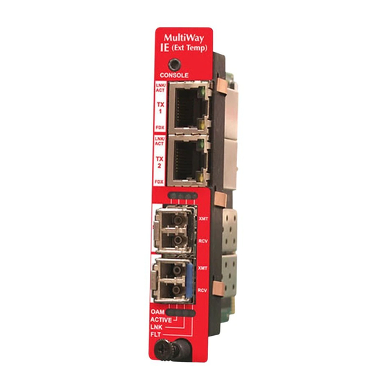
Page 5: About The Ie-Imcv-Multiway
10,240 bytes as well as AutoCross on the copper ports. As an Industrial Ethernet device, it supports an extended temperature range of -40°C to +85°C. A console port and a DIP Switch bay provide configuration options. The IE-iMcV-MultiWay module is a single-wide module. It can be installed in the following chassis: •... - Page 6 • Bandwidth Limiting The IE-iMcV-MultiWay can be installed as a standalone CPE device, back to back, or as a Remote when connected to an iMcV-Giga-FiberLinX-II configured as a Host. As a CPE device, the IE-iMcV-MultiWay can behave as a remote to an iMcV-Giga-...
-
Page 7: Operations, Administration And Maintenance (Oam)
Operations, Administration and Maintenance (OAM) OAM is a general term used in network management and is typically applied to a series of standard protocols for installing, monitoring, and troubleshooting Metropolitan Area Networks. When applied to Ethernet – OAM is typically assumed to refer to the layer 2 (MAC layer), management protocols, specifically 802.3ah and 802.1ag. -
Page 8: Iview² Management Software
Please see the SNMP Management Module manual for software configuration options. iView (iConfig view) iView (iConfig view) is an in-band utility created by IMC Networks, used for SNMP configuration for IMC Networks’ SNMP-manageable devices. The iView (iConfig view) feature allows the following to be performed: •... -
Page 9: Installing An Ie-Imcv-Multiway
Installing an IE-iMcV-MultiWay IE-iMcV-MultiWay can be installed in IMC networks’ unmanaged MediaChassis, IE- MediaChassis series, or the iMediaChassis series. To install an IE-iMcV-MultiWay Remove the blank bracket covering the slot where the module is to be installed by removing the screws on the outside edges of the bracket. -
Page 10: Dip Switch Selectable Mode Configuration
DIP Switch Selectable Mode Configuration The IE-iMcV-MultiWay can be configured in one of the following ways via DIP Switch settings (see page Error! Bookmark not defined.): Configuration Description Method 4-Port Switch In this mode, the unit acts as a standard 4-port MAC-layer switch. -
Page 11: Mini-Serial Port
Name Description Default Switch Setting Dual Enable dual channel Provides 1+1 protection with non-revertive switching 1+1 Revert Provides 1+1 protection with revertive switching LoSpd B Force SFP "B" for low-speed operation LoSpd A Force SFP "A" for low-speed operation Reserved Mini-Serial Port A console port, located at the top of the faceplate, allows the customer to use a local RS-232 serial interface for management. -
Page 12: Led Operation
Glows amber when a fault is detected. Autocross Feature for Twisted Pair Connections All fixed twisted pair ports on the IE-iMcV-MultiWay include AutoCross, a feature that automatically selects between a crossover workstation and a straight-through connection depending on the connected device. -
Page 13: Configuration Options
Configuration Options The following options are configurable through both the iView (iConfig view) and Serial/Telnet. Feature iView² Serial/Telnet Loopback Auto Negotiation Force Mode FlowControl VLANs IP Address Subnet Mask Default Gateway MIB Community Traps Assignment Users Passwords Access Level Reboot Frame size selection Bandwidth Limiting The following table presents management options configurable via iView... -
Page 14: Basic Device Configuration Using The Cli
Basic Device Configuration Using the CLI After running through an initial self test, the screen will display the following message: Press Enter for Device Configuration. Press Enter to open the main configuration screen. This screen allows the user to set the IP address and the destination IP address for traps with the community string, read/write access and password as usual. -
Page 15: Saved And Current Values
This screen contains the following information and options: Saved and Current Values Saved values display the changes made during the current session and current values display the values currently in use: • IP Address (IP address of SNMP agent) • Subnet Mask (mask to define IP subnet to which agent is connected) •... -
Page 16: Assigning Snmp Trap Destinations
The password consists of a combination of any ASCII characters except spaces • Passwords are case sensitive Passwords are a way to make the management of the IMC Networks devices secure, but these password lists must be stored and maintained. Assigning SNMP Trap Destinations Traps are sent by the manageable device to a management PC when a certain event takes place. -
Page 17: Deleting Community Strings
Press E to end a serial port or Telnet/HyperTerminal session before disconnecting the serial cable. This will stop the continuous stream of data to the serial port. Rebooting the Unit To reboot the IE-iMcV-MultiWay, type reboot from the main screen or the command menu. Enabling/Disabling DHCP To toggle DHCP on the IE-iMcV-MultiWay between enable and disable, press D and then Y. -
Page 18: Commands List (Space Bar)
Commands List (Space Bar) The IE-iMcV-MultiWay also includes several device-specific options. To access these options, press the Space Bar from the Main Configuration screen, type the name of the action to be performed (as shown below) and press Enter. Command... -
Page 19: Cleandb
IP and other configurations performed through iView². Downloading Files Firmware and/or saved configuration data for the IE-iMcV-MultiWay can be downloaded via a TFTP connection from a central server via TFTP protocol. Initiate this download via serial configuration or Telnet session. To download a configuration file, type download and press Enter to be taken to the Download a file screen. -
Page 20: Accounts
Once loaded into the device's SNMP memory area, the system prompts the user to reboot the device to make the new configuration active. Accounts The following are the three levels for CLI or Telnet account access: User: View status, change own password, and reboot. Operator: All User privileges mentioned above, plus ability to change settings. - Page 21 When configuring a trunk port, an Ethertype can be user-defined (a trunk port is also defined as a provider port based on 802.1ad). If an Ethertype value comes in a trunk port and is different than the user-defined Ethertype, it will be treated as an unrecognized VLAN tagged frame.
- Page 22 Operation Mode 1 – Mixed Tagged and Untagged Frames In this mode, all tagged and untagged frames pass on any given port. Management to the device can be tagged or untagged. Press the down arrow on the computer keyboard to access additional configuration selections.
-
Page 23: Bandwidth (Bw)
Press the down arrow on the computer keyboard to access the additional configuration commands. Bandwidth (bw) Displays settings for Bandwidth configuration. SFP A/B Ports Ingress Bandwidth Limit Monitors the traffic entering the unit (ingress), discarding (CIR) traffic that exceeds a fixed Committed Information Rate (CIR) plus Burst Allocation (BA). - Page 24 Ingress Burst Allocation Bandwidth Limiting can be set at Ingress of each port individually by setting the MAX Bandwidth Limit in bits/Sec. and the BA in bits. Traffic in excess of the Bandwidth limit plus BA for any time interval will be dropped.
-
Page 25: Version
OSI Level Used in Choose Layer 1, 2 or 3 for the counter, this will Calculations determine how my bytes from the Ethernet frame are to be included in the calculations. (Open Systems Interconnect, referring to Layer 1: Preamble + DA to CRC + IFG the seven layers for Layer 2: Frames DA to CRC... -
Page 26: Viewing Port Statistics (Ifstats)
Viewing Port Statistics (ifstats) To view port statistics on the IE-iMcV-MultiWay, enter ifstats. This will open a screen displaying information on packets received and transmitted as defined by MIB-II standard RFC 1213. Pressing the Space Bar will refresh the data on the screen. -
Page 27: System Description (Sysdescr)
System Description (sysDescr) The sysDescr allows the end user to enter a description for the IMC Networks device. Within the iView² GUI, a name or some kind of identifier can be entered into the text box labeled Description. Once that description is saved, the identifier will be maintained, even if power is interrupted to the unit. -
Page 28: Viewing Sfp Statistics (Sfpstats)
Viewing SFP Statistics (sfpstats) To view SFP statistics on the IE-iMcV-MultiWay, enter sfpstats. This will open a screen displaying SFP information, including vendor, serial number, bit rate and other options. Pressing the Space Bar will refresh the data on the screen. -
Page 29: Port Configuration (Port)
Unit FlowControl displays the following screen: Unit FlowControl globally enables “Pause” frames to be sent. Port Configuration (port) Serial/Telnet sessions display port status as well as allowing configuration of some port features. Type port and press Enter to be taken to the Port screen. From this screen, view the port speed, duplex and link status. - Page 30 The Port screen contains the following commands: Port Enable Enable/Disable the port. (Select Enable to enable the port.) Admin Status Set Administration level. (Select UP to enable management through the port.) Both settings must be enabled to enable the port. Port Speed Ctrl Set the port manually or for Auto Negotiation.
-
Page 31: Using Iview
Windows SNMP services must be installed to receive traps. The autoscan feature of iView² will detect IMC Network devices on an active subnet and list them in the network outline. Click the connection for the IE-iMcV-MultiWay to open its iView² screen. To perform additional configuration, select the iView iConfig view icon on the toolbar in iView². -
Page 32: Unit Configuration
The following functions can be performed via iView Function Description Unit Configuration Display/modify unit information Port Configuration Display/modify port data Bandwidth Displays settings for Bandwidth configuration Tables Display statistics tables, including Unit and Port tables, RMON statistics, MIB-II ifTable and SFP Info. VLAN Provides configuration for VLAN IDs per port Advanced... -
Page 33: Port Configuration
Port Configuration Select Port Configuration to display/modify port information including description and flow control: Bandwidth Select Bandwidth to display configure bandwidth settings for each port. -
Page 34: Tables
Tables Select tables to display a screen from which to select the specific statistics to be viewed Select Unit and Port Tables to display the following information:... -
Page 35: Vlan
VLAN Enter a VLAN ID between 1 and 4,094; possible priority settings are 0 (lowest priority) through 7 (highest priority). *WARNING* If a VLAN # is added to the port and is the same VLAN # assigned for management saving these changes will disrupt management indefinitely. -
Page 36: Advanced
Advanced Select Advanced to reboot the module... -
Page 37: Oam Ah
OAM AH Select OAM AH to display the following screen and monitor the status, configuration, loopback, event log and statistics From the above screen, select Configuration to display state and event configuration information as well as OAM supported functions:... -
Page 38: Loopback Testing
Loopback Testing The IE-MultiWay includes Loopback testing functionality. This feature is selectable via iView2 within the OAM AH configuration. The menu of choices for all ports includes: • Terminate/initiate • Process/ignore OAM Loopback is controlled by using the “Loopback” and “Ignore Rx” control parameters. - Page 39 Select Event Log to display the OAM event log showing fault changes that have occurred via OAM configuration: The OAM Event Log table displays a history of the threshold crossing events and non- threshold crossing events that have occurred at the Ethernet OAM AH Level. There is a maximum of 8 events that can be displayed.
-
Page 40: Oam Cfm
OAM CFM Select OAM CFM to display the following screen and perform administrative control for Maintenance Domains (MDs), Maintenance Assocations (MAs) and Maintenance Association End Points (MEPs). The page contains a list of the local MEPs and provides menu controls to access the administrative functions associated with Create, Delete, and List MD, MA, and MEP information. - Page 41 For the first-time configuration, the user must first create an MD, then an MA, then local and peer MEPs can be added. To create an MD, select the "Configure MD' button to display the OAM CFM Maintenance Domain Configuration page as shown below: NOTE iView...
- Page 42 For the first configuration, create an MA after the MD. Select "Configure MA" to display the OAM CFM Maintenance Association Configuration screen as shown below: NOTE iView will automatically display this page if there is no MA yet defined when the user attempts to access any other menu control.
- Page 43 Select the MD, MA, enter the MEP ID, select the appropriate type, port and direction, and select the Primary VID, if applicable. To cancel the MEP without saving, select Delete. To store the MEP, select Save and the screen is refreshed. Once the user has configured the MD, MA and at least one MEP, a particular instance of an MEP can be accessed for more detailed configuration.
- Page 44 The MEP Instance Configuration page offers more details about an individual MEP as shown below: From this screen, the user can perform the following functions: Function Description Continuity Enable/disable CCMs and verify the number of CCMs that have been sent. Check Instance Verify the current administrative state of the MEP, view the last defect...
-
Page 45: Agent Info
Agent Info Select Agent Info to display SNMP agent data... -
Page 46: Connecting The Ie-Imcv-Multiway To An Imcv-Giga-Fiberlinx-Ii
Connecting the IE-iMcV-MultiWay to an iMcV-Giga-FiberLinX-II If the IE-iMcV-MultiWay is being set up as a Remote (CPE) to a Host connection with an iMcV-Giga-FiberLinX-II, iView provides support for SNMP management of the pair. Several pairs can be managed via UMA through the SNMP management module on the same IP address. -
Page 47: Saving A Configuration File To Disk
The configuration file’s contents is device-type specific and can be identified by iView (iConfig view) as a configuration file as well as to what type of device it is applicable to. Saving a Configuration File to Disk: From the Administration Tab in iView (iConfig view) click the Save Configuration button: The user is prompted for a filename:... - Page 48 The user is prompted to enter any notes to the header of the saved file for future reference when uploading the file through iView (iConfig view): After the file transfer from the device to disk, the user is notified of the status:...
-
Page 49: Uploading A Saved Configuration File Through Iview (Iconfig View)
Uploading a Saved Configuration File through iView (iConfig view) From the Administration Tab in iView (iConfig view) click the Upload Configuration button: The user will be prompted to select a configuration file. Once selected, the user can also view any notes that were added when the file was saved: After selecting the configuration file, the file upload process begins;... -
Page 50: Sfp Ports
SFP Ports The IE-iMcV-MultiWay SFP ports support gigabit fiber SFPs and 100Mbps fiber SFPs, with or without Digital Diagnostics Monitoring Information (DDMI) as well as copper SFPs available in 10/100/1000Mbps and 1000Mbps. DDMI statistics provide real- time access to transceiver operating parameters such as voltage, temperature, laser bias current, and both transmitter and receive optical power. -
Page 51: Rj-45 Data Port Pinout
RS-232 Serial Console Port The IE-iMcV-MultiWay includes an RS-232 Mini Jack for the Console port to allow the end user to launch a serial session and access a list of commands. The serial port on the computer/terminal should be set for: 38.4K baud, 8 data bits, 1 stop bit, no parity, no flow control. -
Page 52: Product Applications
Product Applications For a detailed description of the product applications, please refer to the IE-iMcV- MultiWay data sheet at http://www.imcnetworks.com/Assets/DocSupport/DS-IE- iMcV-MultiWay-1102.pdf. -
Page 53: Glossary
Glossary The following are terms and phrases used within this manual, or which are found in documents associated with this equipment. Term/Acronym Definition The Term “1+1” refers to line protection where identical information is transmitted on two redundant lines. The Receiver chooses the “best”... - Page 54 Term/Acronym Definition MDI/MDIX Media-Dependent Interface/ Media-Dependent Interface Crossover. The ability of an Ethernet port to automatically detect and configure its cabling connections to accommodate crossover or non-crossover wiring, depending on its link partner and cabling. Maintenance Association End Points Management Information Base: A database of objects that can be monitored by a network management system.
-
Page 55: Troubleshooting
MultiWay and its link partner to Auto Negotiation or, if using Force mode, be sure speed and duplex match. IE-iMcV-MultiWay allows the end user to assign a VLAN tag to all management traffic (SNMP and telnet). It is important to understand that IF using telnet or... -
Page 56: Specifications
• • IEEE 802.3i 10Base-T twisted pair IEEE 802.3u 100Base-FX or SX fiber 1-year warranty for SFP IMC Networks Technical Support Tel: (949) 465-3000 or (800) 624-1070 (in the U.S. and Canada); +32-16-550880 (Europe) Fax: (949) 465-3020 E-Mail: techsupport@imcnetworks.com Web:... -
Page 57: Fiber Optic Cleaning Guidelines
Dust caps are installed at IMC Networks to ensure factory-clean optical devices. These protective caps should not be removed until the moment of connecting the fiber cable to the device. Should it be necessary to disconnect the fiber device, reinstall the protective dust caps. -
Page 58: Electrostatic Discharge Precautions
Electrostatic Discharge Precautions Electrostatic discharge (ESD) can cause damage to any product, add-in modules or stand alone units, containing electronic components. Always observe the following precautions when installing or handling these kinds of products Do not remove unit from its protective packaging until ready to install. Wear an ESD wrist grounding strap before handling any module or component. -
Page 59: Safety Certifications
Directive on Electrical Equipment Designed for use within Certain Voltage Limits (2006/95/EC). Certified to Safety of Information Technology Equipment, Including Electrical Business Equipment. For further details, contact IMC Networks. Class 1 Laser product, Luokan 1 Laserlaite, Laser Klasse 1, Appareil A’Laser de Classe 1... - Page 60 The information in this document is subject to change without notice. IMC Networks assumes no responsibility for any errors that may appear in this document. IE-iMcV-MultiWay is a trademark of IMC Networks. Other brands or product names may be trademarks and are the property of their respective companies.
Need help?
Do you have a question about the IE-iMcV-MultiWay and is the answer not in the manual?
Questions and answers