Icom IC-A210 Instruction Manual
Vhf air band transceiver
Hide thumbs
Also See for IC-A210:
- Service manual (233 pages) ,
- Instruction manual (40 pages) ,
- Installation manual (2 pages)

Subscribe to Our Youtube Channel
Related Manuals for Icom IC-A210


Summary of Contents for Icom IC-A210
- Page 1 INSTRUCTION MANUAL VHF AIR BAND TRANSCEIVER iA210 This device complies with Part 15 of the FCC Rules. Operation is subject to the condition that this device does not cause harmful interference.
-
Page 2: Explicit Definitions
❍ Large, bright OLED display carefully and completely before using the transceiver. A fixed mount VHF airband first, the IC-A210 has an organic light emitting diode (OLED) display. The all man-made lighting emits its own light and the display offers many advantages in brightness, SAVE THIS INSTRUCTION MANUAL —... -
Page 3: Precautions
This connection will not only blow fuses but also may damage the transceiver. FCC caution: Changes or modifications to this transceiver, not expressly approved by Icom Inc., could void your authority to operate this transceiver under FCC regulations. -
Page 4: Table Of Contents
■ Memory mode menu ( Regular and group memory channels only) ···································12 Icom, Icom Inc. and the Icom logo are registered trademarks of Icom Incor- ■ Regular memory channel ································································13 porated (Japan) in Japan, the United States, the United Kingdom, Germany, ■... -
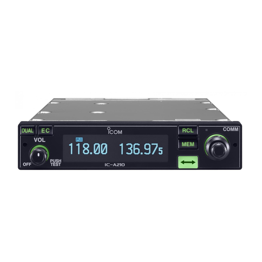
Page 5: Panel Description
PANEL DESCRIPTION ■ Front panel COMM DUAL MEMORY 118.00 121.52 CH09 SAMPLE PUSH TEST iA210 q DUAL SWITCH [DUAL] e VOLUME/POWER SWITCH [VOL] ➥ Push to turn DualWatch operation ON or OFF (p. 8). ➥ Turn [VOL] to switch the power ON or OFF (p. 5). ➥... - Page 6 PANEL DESCRIPTION ■ Front panel (Continued) COMM DUAL MEMORY 118.00 121.52 CH09 SAMPLE PUSH TEST iA210 i INNER (Small) TUNING DIAL [DIAL] t MEMORY SWITCH [MEM] ➥ Rotate to set the standby frequencies (kHz digit) Hold down for 2 seconds to program a displayed fre- (p.
-
Page 7: Rear Panel
28 for details. q Metal catch (For Icom products) e DC, MICROPHONE, SPEAKER, HEADPHONE AND Use to attach to an installation rack for Icom products. DATA JACK Refer to the “INSTALLATION GUIDE” for details. Connect a 13.8 V or 27.5 V DC power supply, speaker,... -
Page 8: Function Display
PANEL DESCRIPTION ■ Function display t DUALWATCH INDICATOR Appears when the DualWatch function is active (p. 8). y MEMORY CONDITION INDICATOR DUAL MEMORY ➥ Indicates “MEMORY” when the regular memory chan- nel is selected (p. 13). 118.00 121.52 ➥ Indicates “GRP01–GRP20” when the group memory channel is selected (p. -
Page 9: Basic Operation
BASIC OPERATION ■ Frequency selection ■ Standby frequency selection (Step 1-2) IC-A210 has two ways to select a desired frequency. CAUTION: DO NOT turn the power ON until the air- ï General frequency selection craft engines have been started. It is very important for Select a desired frequency which is used for the next operat- protection of the power supply circuit. -
Page 10: Frequency Exchanging (Step 2-2)
BASIC OPERATION ■ Frequency exchanging ■ Receiving (Step 2-2) q Select an operating frequency. • Refer to pages 5, 6 for details. q After selecting the standby frequency, push [↔] to ex- • “RX” appears when receiving a signal or opening squelch. change it with the active frequency. -
Page 11: Frequency Setting Example
BASIC OPERATION ■ Frequency setting example The following example shows to how to set 126.40 MHz as the standby frequency and then exchange it with the active fre- quency indicator. STEP DISPLAY NOTE Previously used frequencies appear. 134.80 121.80 q Rotate [O-DIAL] clockwise to Rotate the large tuning dial to change 134.80 126.80... -
Page 12: Direct Frequency Setting Mode Operation
BASIC OPERATION ■ Direct frequency setting ■ DualWatch operation mode operation The DualWatch operation monitors the active frequency at certain intervals even when receiving a signal on the The direct frequency setting mode operation is useful when standby frequency. When a signal is received on the active setting a desired frequency directly as the active frequency. -
Page 13: Memory Operation
They are used for monitoring NOAA (National Oceanic ï Memory protect function and Atmospheric Administration) broadcasts (reception of IC-A210 has a memory protect function. The function pre- weather memory channels possible in U.S.A. version only). vents accidental changes or deletion. -
Page 14: Channel Selection
MEMORY OPERATION ■ Channel selection ■ Programming a memory channel The transceiver has 10 channels in regular memory and 200 channels in the group memory. There are 10 channels in To program the memory channels, follow the steps below. each of 20 groups (GRP01–GRP20). q Push [RCL] to enter the memory mode. -
Page 15: Programming Example
MEMORY OPERATION ■ Programming example The following is an example showing how to program 126.000 MHz into regular memory channel 4. “126.00” appears in the standby Set a “126.000 MHz” in the 134.80 126.00 display. standby display. MEMORY “MEMORY” and the channel number [RCL], Push then... -
Page 16: Transferring Memory Contents
MEMORY OPERATION ■ Transferring memory ■ Memory mode menu contents ( Regular and group memory channels only) This function transfers a memory channel’s contents into the active frequency display and places the previous active ï REPLACE frequency into the standby display. Replacing the standby frequency with the memory channel frequency. -
Page 17: Regular Memory Channel
MEMORY OPERATION ■ Regular memory channel ■ Group memory channel The transceiver has 10 regular memory channels. The transceiver has 200 group memory channels comprised of 10 channels in each of 20 groups. Five programming options are selectable. The following functions are available. The following functions are available. -
Page 18: History Memory Channel
MEMORY OPERATION ■ History memory channel ■ Clearing the memory contents ( Regular and group memory The transceiver has 10 history memory channels. channels only) The standby frequency is stored into a history memory chan- nel when pushing [↔]. Unwanted memory channels can be cleared. The frequency is stored into the history memory channel in q Push [RCL] to select memory mode. -
Page 19: Programming Channel Names (Regular Memory Channel Only)
MEMORY OPERATION ■ Programming channel names ■ Programming group names (Regular memory channel only) (Group memory channel only) The regular memory channel can display a six character The memory groups can display a six character name in ad- name in addition to the memory number. dition to the group number (“GRP01”–“GRP20”). -
Page 20: Programming Channel Tag (Group Memory Channel Only)
MEMORY OPERATION ■ Programming channel tag ■ Channel tag list (Group memory channel only) DISPLAY MEANS NAME Group* GPS* The tag name can be set a three character name in addition _ _ _ – Non-tag to the group number. It is convenient for separating memory Tower type. -
Page 21: Weather Memory Channel (U.s.a. Version Only)
MEMORY OPERATION ■ Weather memory channel ■ GPS memory (U.S.A. version only) When connected to an external GPS receiver* equipped with an airport frequency database, frequency data such as The U.S.A. version has VHF marine WX (weather) channel nearby airports can be transferred and made available in the receiving capability for flight planning. -
Page 22: Gps Memory Edit
MEMORY OPERATION ■ GPS memory edit ■ Memory protection The received GPS memory data is stored in the desired The transceiver has memory protection which inhibits to group memory channel. the editing (storing, deleting, replacing, etc.) of the memory group memory channels. NOTE: The GPS memory data is overwritten if the se- Refer to “Memory Protection”... -
Page 23: Other Functions
The lock function prevents accidental frequency changes and accidental function activation. The IC-A210 can be set to the 121.5 MHz emergency fre- q Hold down [DIAL] for 2 seconds to turn the lock function quency quickly. This function can be activated even when the key lock function is in use. -
Page 24: Intercom Function
OTHER FUNCTIONS ■ Intercom function ■ Squelch test function When two headphone and microphone jacks are connected This function opens the squelch manually for testing. to the transceiver, these headsets can be used as a voice- q Push [VOL] to turn the squelch test function ON. activated intercom. -
Page 25: Weather Memory Channel Scan (U.s.a. Version Only)
OTHER FUNCTIONS ■ Weather memory channel scan (U.S.A. version only) Scanning searches for weather channel signals automati- cally and makes it easier to listen purposes. Repeatedly scans all weather memory channels. This function is available for the U.S.A. version only. q Set to the weather memory channel mode. -
Page 26: Menu Mode
MENU MODE ■ MENU mode programming • MENU mode items TX MIC SEL SQL LEVEL MENU mode is available at power ON and allows you to set DISP MODE FM SQL LV* seldom-changed settings. In this way you can customize p. -
Page 27: Menu Mode Items
MENU MODE ■ MENU mode items D Intercom2 Microphone Audio Input Level D AM Squelch Level “SQL LEVEL” “INCOM LV2” Set the squelch level for AM mode operation. Set the intercom2 microphone input level. In order to receive signals properly, as well as for the scan to function effectively, the squelch must be adjusted to the •... -
Page 28: Group Memory Channel Display
MENU MODE ■ MENU mode items (Continued) D Automatic Noise Limiter “ANL” D Priority Watch Interval “PRI. WATCH” Set the active frequency receive interval time while receiving The ANL (Automatic Noise Limiter) function reduces noise the standby frequency. components such as that caused by engine ignition systems while receiving. -
Page 29: Transmitting Microphone Selection
MENU MODE D Microphone2 Gain “MIC2 GAIN” D Dimmer Mode “DISP MODE” Set the microphone2’s gain. The light sensor which is built into the display is used for this • –010 to 010 : Setting the microphone2’s gain from –10 to +10. function. - Page 30 MENU MODE ■ MENU mode items (Continued) D Dimmer Brightness (Manually) “DISP MAN.” D USER-2 Setting “U-2 ID SET” Set the USER-2, channel tag, to a desired ID. Set the brightness manually to suit your own preferences. q Push [MEM] to enter the U-2 ID edit mode. •...
- Page 31 MENU MODE D Beep Tone Level “BEEP” D Interlock “INTERLOCK” Confirmation beep tones normally sound when storing mem- When two transceivers are connected together, the interlock ory, operating time-out-timer function, etc. These can be set function can prevent them from transmitting at the same a desired beep level as you prefer.
-
Page 32: Cloning
CLONING D Data cloning • When clone writing error occurs. Cloning allows you to quickly and easily transfer the programmed contents or data from a PC to a transceiver CLONE using the optional CS-A210 CLONING SOFTWARE WRITE ERR Data can be cloned to and from a PC (IBM compatible) using the optional CS-A210 and the op- CLONING SOFTWARE... -
Page 33: Options
Approved Icom optional equipment is designed for optimal performance when used with an Icom transceiver. Icom is not responsible for the destruction or damage to an Icom transceiver in the event the Icom transceiver is used with equipment that is not manufactured or approved by... -
Page 34: Specifications
SPECIFICATIONS D General D Transmitter • Frequency range : 118.000 to 136.975 MHz • Mode : AM 161.650 to 163.275 MHz* • Output power : 8 W (Carrier power) • Channel spacing : 25 kHz or 8.33 kHz* • Spurious emissions : –60 dBc •... - Page 35 SPECIFICATIONS (VFO CHANNEL ID LIST) • Channel spacing: 25 kHz (Actual frequency is displayed.) Operating Frequency Channel spacing Channel ID* (MHz) (kHz) (Displayed Frequency) 118.0000 118.000 118.0250 118.025 118.0500 118.050 118.0750 118.075 118.1000 118.100 • Channel spacing: 8.33 kHz Operating Frequency Channel spacing Channel ID* (MHz)
-
Page 36: Safety Training Information
Electromagnetic Interference/Compatibility antenna as worst case, the antenna shall be located on During transmissions, your Icom radio generates RF energy the roof top at any place on the centre line along the that can possibly cause interference with other devices or vehicle in order to achieve 36 centimeters separation systems. - Page 37 2. Il faut que l'antenne émettrice de cet appareil soit placée à l'extérieur d'un véhicule et tenue éloignée d'au moins En mode de transmission, votre radio Icom produit de l'éner- 36 centimètres de toute personne pendant le fonction- gie de RF qui peut provoquer des interférences avec d'autres nement.
-
Page 38: For Class B Unintentional Radiators
FOR CLASS B UNINTENTIONAL RADIATORS This equipment has been tested and found to comply with the limits for a Class B digital device, pursuant to part 15 of the FCC Rules. These limits are designed to provide reason- able protection against harmful interference in a residential installation. -
Page 39: Index
INDEX Frequency setting example ·······························7 Microphone2 gain ··········································25 Accessing 121.5 MHz emergency frequency ·19 Frequency step setting ···································20 AM squelch level ·············································23 Front panel························································1 Operating menu mode ····································22 Automatic noise limiter ···································24 Function display ················································4 Other functions ···············································19 Basic operation ·················································5 General frequency selection ·····························5 Panel descriptions ············································1 Beep tone level ···············································27... - Page 40 A-6602H-1EX-y Printed in Japan 2007–2011 Icom Inc. © 1-1-32 Kamiminami, Hirano-ku, Osaka 547-0003, Japan Printed on recycled paper with soy ink.
Need help?
Do you have a question about the IC-A210 and is the answer not in the manual?
Questions and answers