Icom iC-A210E Instruction Manual
Vhf air band transceiver
Hide thumbs
Also See for iC-A210E:
- Installation manual (2 pages) ,
- Service manual (233 pages) ,
- Instruction manual (40 pages)
Table of Contents
Advertisement
Quick Links
Download this manual
See also:
Installation Manual
Advertisement
Table of Contents

Subscribe to Our Youtube Channel
Related Manuals for Icom iC-A210E


Summary of Contents for Icom iC-A210E
- Page 1 INSTRUCTION MANUAL VHF AIR BAND TRANSCEIVER iA210E...
-
Page 2: Explicit Definitions
The IC-A210E has a built-in voice activated intercom function allow- IBM is a registered trademark of International Business Machines. ing the pilot to talk with a co-pilot via headset. The IC-A210E has ad- Microsoft and Windows are registered trademarks of Microsoft Corporation in the U.S.A. -
Page 3: Precautions
PRECAUTIONS R WARNING! NEVER DO NOT place unit in a non-secure place to avoid inad- operate the transceiver with a vertent use by children. headset or other audio accessories at high volume levels. Hearing experts advise against continuous high volume op- DO NOT push the PTT when not actually desiring to trans- eration. -
Page 4: Table Of Contents
TABLE OF CONTENTS IMPORTANT .....................i Programming channel names (Regular memory channel only) ...15 EXPLICIT DEFINITIONS................i Programming group names (Group memory channel only) ..15 FEATURES ....................i Programming channel tag PRECAUTIONS..................ii (Group memory channel only) ............16 TABLE OF CONTENTS................iii Channel tag list................16 1 PANEL DESCRIPTION..............1–4 GPS memory................17 Front panel ..................1... -
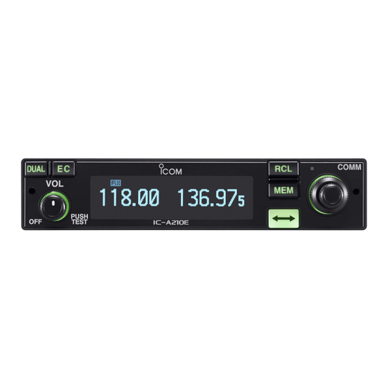
Page 5: Panel Description
PANEL DESCRIPTION I Front panel COMM DUAL EC MEMORY 118.00 121.52 CH09 SAMPLE PUSH TEST iA210E q DUAL SWITCH [DUAL] e VOLUME/POWER SWITCH [VOL] ➥ Push to turn dualwatch operation ON or OFF (p. 8). ➥ Turn [VOL] to switch the power ON and OFF (p. 5). ➥... - Page 6 PANEL DESCRIPTION I Front panel (Continued) COMM DUAL EC MEMORY 118.00 121.52 CH09 SAMPLE PUSH TEST iA210E t MEMORY SWITCH [MEM] i INNER (Small) TUNING DIAL [DIAL] ➥ Push and hold for 2 sec. to be programmed a displayed ➥ Rotate to set the standby frequencies (kHz digit) (p. 5), frequency to any blank regular memory channel or memory channels (p.
-
Page 7: I Rear Panel
DATA JACK Connects an optional cloning cable (OPC-1529R). Refer q Metal catch (For Icom products) to p.27 for details. Use to attach to an installation rack for Icom products e DC, MICROPHONE, SPEAKER, HEADPHONE AND (p. 26). DATA JACK w Metal catch (For 3rd party products*) Connects a 13.8 V or 27.5 V DC power supply, speaker,... -
Page 8: I Function Display
PANEL DESCRIPTION I Function display t DUALWATCH INDICATOR Appears when the dualwatch function is active (p. 8). y MEMORY CONDITION INDICATOR DUAL MEMORY ➥ Indicates “MEMORY” when the regular memory channel 118.00 121.52 is selected (p. 13). ➥ Indicates “GRP01–GRP20” when the group memory channel is selected (p. -
Page 9: Basic Operation
BASIC OPERATION I Frequency selection I Standby frequency selection (Step 1-2) IC-A210E has 2 ways to select the desired frequency. CAUTION: ï General frequency selection DO NOT turn the power ON until the aircraft engines have Select the desired frequency which is used for the next oper- been started. -
Page 10: I Frequency Exchanging/Not Exchanging (Step 2-2)
BASIC OPERATION I Frequency exchanging/ I Receiving not exchanging (Step 2-2) q Select an operating frequency. • Refer to pgs. 5–6 in details. q After selecting the standby frequency, push [↔] to ex- • “RX” appears when receiving a signal or opening squelch. change the standby frequency with the active frequency. -
Page 11: I Frequency Set Example
BASIC OPERATION I Frequency set example The following example shows to how to select 126.40 MHz in the standby frequency indicator and then exchange it to the active frequency indicator. 134.80 121.80 Previously used frequencies appear. Rotate the large tuning dial to change 134.80 126.80 the standby frequency in MHz steps. -
Page 12: I Direct Frequency Setting Mode Operation
BASIC OPERATION I Direct frequency setting I Dualwatch operation mode operation The dualwatch operation monitors the active frequency in in- tervals even when receiving a signal on the standby fre- The direct frequency setting mode operation is useful when quency. When a signal is received on the active frequency, setting the desired frequency directly to the active frequency the radio switches to the active frequency and stays on the indicator. -
Page 13: Memory Operation
There are up to 200 group channels (10 CH × 20 Groups). ï Memory protect function The following functions are available: IC-A210E has a memory protect function. The function pre- REPLACE, DELETE, REVIVE, GROUP NAME EDIT and vents accidental changes or deletion. -
Page 14: I Channel Selection
MEMORY OPERATION I Channel selection I Programming a memory channel The transceiver has 10 regular memory and 200 group channels (10 channels × 1 REGULAR MEMORY and 10 This transceiver is equipped with 10 regular memory and 200 channels × 20 GROUPS) for storage of often-used group channels. -
Page 15: I Programming Example
MEMORY OPERATION I Programming example The following is an example showing how to program 126.000 MHz into regular memory channel 4. “126.00” appears in the standby Set a “126.000 MHz” in the 134.80 126.00 indicator. standby indicator. MEMORY “MEMORY” and regular memory Push [RCL], then rotate [O- 134.80 channel number appear. -
Page 16: I Transferring Memory Contents
MEMORY OPERATION I Transferring memory I Memory mode menu contents (Regular and group memory channels only) This function transfers a memory channel’s contents into the active frequency indicator. ï REPLACE Replacing the selected memory channel to the standby fre- q Push [RCL] to enter the memory mode. quency. -
Page 17: Memory Channel
MEMORY OPERATION I Regular memory channel I Group memory channel The transceiver has 200 memory channels 200 group The transceiver has 10 regular memory channels. 5 actions channels (10 channels × 20 groups). 6 actions are selectable. are selectable. q Push [RCL] to enter the memory mode. q Push [RCL] to enter the memory mode. -
Page 18: I History Memory Channel
MEMORY OPERATION I History memory channel I Clearing the memory contents (Regular and group memory The transceiver has 10 history memory channels. channels only) The standby frequency is stored into a history memory chan- nel when pushing [↔]. Unwanted memory channels can be cleared. The frequency is stored into the history memory channel in q Push [RCL] to select memory mode. -
Page 19: I Programming Channel Names (Regular Memory Channel Only)
MEMORY OPERATION I Programming channel names I Programming group names (Regular memory channel only) (Group memory channel only) The regular memory channel can display a 6-character name The group memory channel can display a 6-character name in addition to the memory number. in addition to the group number (“GRP01”–“GRP20”). -
Page 20: I Programming Channel Tag (Group Memory Channel Only)
MEMORY OPERATION I Programming channel tag I Channel tag list (Group memory channel only) DISPLAY MEANS NAME Group* GPS* The tag name can be set a 3-character name in addition to _ _ _ – Non-tag the group number. It is convenient for separating memory type. -
Page 21: Igps Memory
MEMORY OPERATION I GPS memory I GPS memory edit When connected to an external GPS receiver* equipped with The received GPS memory data is stored to desired group an airport frequency database, frequency data such as memory channel. nearby airports can be transferred and made available in the NOTE: The GPS memory data is overwritten if the setting GPS memory (maximum 10-memory channels). -
Page 22: Other Functions
The lock function prevents accidental frequency changes and accidental function activation. The IC-A210E can be set to the 121.5 MHz emergency fre- q Push and hold [DIAL] for 2 sec. to turn the lock function quency quickly. This function can be activated even when the key lock function is in use. -
Page 23: I Intercom Function
OTHER FUNCTIONS I Intercom function I Squelch test function When 2-headphone and microphone jacks are connected to This function opens the squelch manually for testing. q Push [VOL] to turn the squelch test function ON. the transceiver, these headsets can be used as a voice-acti- vated intercom. -
Page 24: Menu Mode
MENU MODE I MENU mode programming • MENU mode items MENU mode is available at power ON and allows you to set DISP MODE HP LEVEL seldom-changed settings. In this way you can customize INCOM LV1 DISP LOW p. 23 transceiver operations to suit your preferences and operating style. -
Page 25: Imenu Mode Items
MENU MODE I MENU mode items D Headphone Level “HP LEVEL” D Intercom1 Squelch Level “MIC1 SQL” Set the headphone output level while receiving. Set the intercom1 squelch level. • AF gain : The output level is same as [VOL]. The setting level is required to open the squelch when speak- •... -
Page 26: Group Memory Channel Display
MENU MODE I MENU mode items (Continued) D AM Squelch Level “SQL LEVEL” D Memory Protection “MEM PROTECT” Set the squelch level for AM mode operation. Set the memory protection to regular memory channels and In order to receive signals properly, the squelch must be ad- group memory channels. -
Page 27: Transmitting Microphone Selection
MENU MODE I MENU mode items (Continued) D Sidetone Level “SIDETONE LV” D Dimmer Mode “DISP MODE” When using an optional headset (supplied from 3rd party*) Set the OLED dimmer mode. • OFF : The dimmer function is OFF. via the adapter, the transceiver outputs your transmitted voice •... - Page 28 MENU MODE I MENU mode items (Continued) D Dimmer Brightness (Manually) “DISP MAN.” D USER-1 Setting “U-1 ID SET” Set the brightness manually to suit your own preferences. Set the USER-1, channel tag, to the desired ID. q Push [MEM] to enter the U-1 ID edit mode. •...
- Page 29 MENU MODE I MENU mode items (Continued) D External Input Level “AUX LEVEL” D Time-Out-Timer “TIME OUT” Set the external input level. To prevent accidental prolonged transmission, etc., the trans- • OFF (0) : The external input does not operate. ceiver has a time-out-timer function.
-
Page 30: Installation And Removal
I Transceiver removal CAUTION: Treat the flat cable with care when disconnecting it. The IC-A210E may easily be removed from the installation rack, if desired. r Visually confirm that the metal catches on the top and bot- q Perform the same steps as q–e of “Transceiver installa- tom of the transceiver are as shown below. -
Page 31: Cloning
CLONING D Data cloning • When clone writing error occurs. Cloning allows you to quickly and easily transfer the programmed contents or data from a PC to a transceiver CLONE WRITE ERR using the optional CS-A210 CLONING SOFTWARE Data can be cloned to and from a PC (IBM compatible) using the optional CS-A210 and the optional OPC- CLONING SOFTWARE... -
Page 32: Specifications
SPECIFICATIONS D General D Receiver • Frequency range : 118.000 to 136.975 MHz • Receive system : Double conversion • Channel spacing : 25 kHz or 8.33 kHz superheterodyne • Frequency stability : ±1 ppm (0˚C to +40˚C) • Intermediate frequencies : 1st 38.85 MHz •... -
Page 33: Options
MOUNTING BRACKET For mounting the transceiver. The external speaker and mi- crophone are included. NOTE: Icom optional equipment is designed for optimal per- formance when used with this transceiver. We are not re- sponsible for the transceiver being damaged or any... -
Page 34: About Doc
ABOUT DOC DECLARATION OF CONFORMITY We Icom Inc. Japan 0168 1-1-32, Kamiminami, Hirano-ku Osaka 547-0003, Japan Declare on our sole responsibility that this equipment complies with the essential requirements of the Radio and Telecommunications Terminal Equipment Directive, 1999/5/EC, and that any applicable Essential Test Düsseldorf 26th Sep. - Page 35 ABOUT DOC CE Versions of the IC-A210E which display • List of Country codes (ISO 3166-1) the “CE” symbol on the serial number seal, Country Codes Country Codes comply with the essential requirements of the European Radio and Telecommunication Ter-...
-
Page 36: Index
INDEX About DOC.....................30 FM squelch level ..................22 Accessing 121.5 MHz emergency frequency.........18 Frequency display ..................24 AM squelch level ..................22 Frequency exchanging/not exchanging ...........6 Automatic noise limiter ................21 Frequency selection .................5 Frequency set example................7 Frequency step ..................25 Basic operation ..................5 Frequency step setting................19 Beep tone level ..................25 Front panel ....................1 Blank channel...................9... - Page 37 INDEX Transceiver installation ................26 Memory channel type................9 Transceiver removal................26 Memory clear ..................25 Transferring memory contents ...............12 Memory mode menu ................12 Transmitting .....................6 Memory operation ..................9 Transmitting microphone selection ............23 Memory protect function................9 Memory protection ................17, 22 Menu mode items...................21 USER-1 setting ..................24 Menu mode programming ..............20 USER-2 setting ..................24 Microphone1 gain ..................22...
- Page 38 M E M O...
- Page 39 M E M O...
- Page 40 A-6606H-1EU-e Printed in Japan 2008 Icom Inc. © 1-1-32 Kamiminami, Hirano-ku, Osaka 547-0003, Japan Printed on recycled paper with soy ink.
Need help?
Do you have a question about the iC-A210E and is the answer not in the manual?
Questions and answers