Table of Contents
Advertisement
Quick Links
AUDIO/VIDEO
CONTROL
RECEIVER
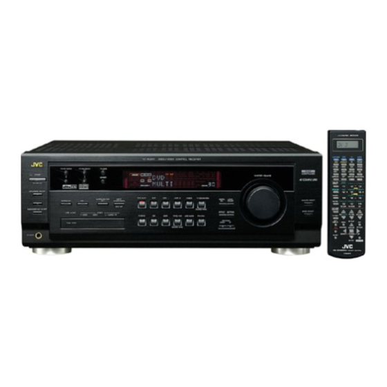
RX-8020VBK
J
f
E .........
,4VC_"_VI.,_ LINK
......................
_ __ii
¸
I
............
INSTRUCTIONS
DO_
DIGITAL.
EX
For Customer Use:
Enter below the Model No. and Serial
No. which are located either on the rear,
bottom or side of the cabinet. Retain this
information for future reference.
Model No.
Serial No.
LVT0870-001A
[4
Advertisement
Table of Contents

Related Manuals for JVC RX-8020VBK


Summary of Contents for JVC RX-8020VBK
- Page 1 AUDIO/VIDEO CONTROL RECEIVER RX-8020VBK ,4VC_"_VI.,_ LINK ........_ __ii ¸ E ..DIGITAL. INSTRUCTIONS For Customer Use: Enter below the Model No. and Serial No. which are located either on the rear, bottom or side of the cabinet. Retain this information for future reference.
- Page 2 RX-8020VBK enclosure that sufficient Trade Name: magnitude to constitute a risk of electric Responsible Party: JVC Americas Corp. shock to persons. Address: 1700 Valley Road, Wayne New Jersey 07470 The exclamation point within an equilateral Telephone Number: 973-315-5000 triangle is intended to alert the user to the...
- Page 3 For Canada/pour Le Canada THIS DIGITAL APPARATUS DOES NOT EXCEED THE CLASS B LIMITS FOR RADIO NOISE EMISSIONS PROM DIGITAL APPARATUS AS SET OUT IN THE INTERFERENCE-CAUSING EQUIPMENT STANDARD ENTITLED "DIGITAL APPARATUS," ICES-003 OF THE DEPARTMENT OF COMMUNICATIONS. CET APPAREIL NUMERIQUE RESPECTE LES LIMITES DE BRUITS RADIOELECTRIQUES...
-
Page 4: Table Of Contents
Reproduce Multi-channel Digital Software ........AV COMPU LINK Remote Control System ..49 Setting the Speaker Distance ..........Operating JVC's Audio/Video Component• ... 51 Setting the Bass Sounds ............. iSI Setting the Dynamic Range ..........Operating Audio Conlponents .......... - Page 5 LINK remote control systems These COMPU LINK remote control systems allow you to operate other JVC's audio/video components from this receiver. Manufactured under license from Dolby Laboratories. "Dolby," "Pro Logic," and the double-D symbol are trademarks of Dolby Laboratories. "DTS," "DTS-ES Extended Surround" and "Neo:6" are trademarks...
- Page 6 Parts Identification Become familiar with the buttons and consols on the receiver before use. Refer to the pages in parentheses for details. Front Panel Display Window _____ _____ When using the VIDEO input terminals 11111 iiiiiiiiiiiiiiiiiiii .ii and/or USB AUDIO terminal on the front panel, detach the terminal cover.
- Page 7 Remote Control Remote Control Display window ©/I buttons(t6,53 C,_W/DBS O/I ,VCRt O/I/iN O/I, AUDIO O/I AN CONTROL RECEIVER Source selecting buttons (I 6, 17, 19, 27, 28, 37) DVD, DVD MULTI, CD, FM/AM, TV/DBS, VIDEO, CDR. PHONO, VCRI, VCR2, 'IAPE/MD, USB SURROUND button (36) DSP button (36) ANALOG DIRECT button (30)
- Page 8 Getting Started This section explains how to connect audio/video components and speakers to the i_ceivec and hew to connect power supply General Precautions FM Antenna Connections • Be sure your hands al_ dry. • Turn the power off to all components. •...
- Page 9 AM Antenna Connections ANTENNA-- Turn the loop until yon have You can connect the following speakers: F_ 75,2 the best reception. • Two pairs of front speakers to produce normal s/ereo sound. • One pair of surround speakers to mtjoy the surround effect. •...
- Page 10 Basic connecting procedure 1 Cut, twist and remove the insulation at the end of each speaker signal cable (not supplied). Turn the knob counterclockwise. Insert the speaker signal cable. Turn the knob clockwise. For each speaker (except for a subwoofer), connect the (+) and (-) lerminals...
- Page 11 Enhancing your audio system You can use this receiver as the pre-amplifier (control amplifier) when you connect power amplifiers to the PRE OUT jacks on the You can connect the folk)wing audio/video components to this mar panel using cables with RCA pin plugs (not supplied). receiver.
- Page 12 I CDplayer ] _D recorder] CD recorder To audio output To audio input To audio output Cassettedeck or MD recorder Cassette deck To audio input To audio output If your audio components have a COMPU LINK or TEXT COMPU LINK jack PiONO •...
- Page 13 IMPORTANT: Video component connections This receiver is equipped with the following video jacks--composite Use the cables with RCA pin plugs (not supplied). video, S-video and component video jacks. You can use any of the Connect the white plug to the audio left jack, the red plug to the three to connect a video component.
- Page 14 TV and/or DBStuner When connecting the TV to the AUDIO jacks (TV SOUND/DBS), DO NOT connect the TV's video output to these v deo nput acks. LEFT I®® Connect the TV to the appropriate MONITOR OUT jacks to view a play-backing picture from other connected...
- Page 15 DVD player • When you connect a DVD player with stereo output,jacks: LEF_ ® ® I®® DVD player [®® k.....L.." MONITOR i', ..............• iAJ To front left/right audio output To S-video output To component video output To composite video output •...
- Page 16 Notes: • Digital Connections • When shipped from the factory, the DIGITAL IN terminals have This _ceiver is equipped with _ur DIGITAL IN _rminals_ne been set for use with the following components: digital coaxial terminal and three digital optical terminals_nd - DIGITAL 1 (coaxial): For DVD player DIGITAL OUT terminal.
- Page 17 • Check if the drivers are correctly installed. Connection I. Open the Control Panel on your PC: Select IStart] "* This receiver is equipped with a USB terminal on the front panel. [Sellings] --+ [Control Panel]. You can connect your PC to this terminal and enjoy sound 2.
- Page 18 Before plugging the receiver into an AC outlet, make sure that all Before using the x-emole control, put two supplied batteries first. connections have been made. When using the remole control, aim the remote control directly the remote sensor on the receiver. Plug the power cord into an AC outlet.
- Page 19 Basic Operations The following operations are commonly used when you play any sound sources. using Before remote control Note: • How to confirm the remote control operation mode A small amount of power is consumed in standby mode, To turn the The display window oil the remole...
- Page 20 From the remote control: Changing the source name When you have conneOed all MD recorder to the TAPE/MD jacks £Z£:, i£22;, 0 or a DBS tuner to the TV SOUND/DBS ,jacks on the rear panel, I, _ _i_ _!i _l!it_i! PHONO change the source name which will be shown on the display.
-
Page 21: Speakers On/Off 1
To use neither sets of the speakers, press SPEAKERS ON/OFF and SPEAKERS ON/OFF 2 so that the SPEAKERS 1 and SPEAKERS 2 indicators disappear from the display. On the front panel: The HEADPHONE indicator lights up and "HEADPHONE" To increase the wflume, turn MASTER appears on the display. -
Page 22: In) Terminals
DGTL AUTO: Select this for the digital input mode. The receiver automatically detects the incoming signals. The DGTL AUTO indicator lights up on the When you have connected digital source components using the display, and the digital signal formal indicators digital ierminals (see page 13), you need to change the input mode... -
Page 23: Sleep
When the shut-off time comes: The receiver turns off automa/ically. From the remote control ONLY: To check or change the time remaining until the shut-off time: Press MUTING to mute the sound through MUTING Press SLEEP once. all speakers and headphones connected. - Page 24 Basic Settings Some of the following settings are required after connecting and positioning your speakers while others will make operations easien • When performing the basic settings, it is recommended to use the remote control so that you can show the on-screen display on the T_ •...
- Page 25 Surround back speakers quantity--S BACK (SBACK] Setting the Speakers To obtain the best possible surround sound from the Surround and tOn-screen display] [Front panel] DSP modes, you have to register the setting about the speaker arrangement after all connections are completed..........
- Page 26 Selecting Channel Numbers to Reproduce Setting the Speaker Distance Multi_hannel Digital Software_X/ES The distance fiom your listening point to the speakers is another [On-screen display] [Front panel] important element to obtain the best possible sound of the Surround and DSP modes. You need to set the distance from your listening point to the speakers.
-
Page 27: Midnight Mode
4[_ Setting the Bass Sound• Sett ng the Dynamic Range--MID NIGHT You can adjust subwoofer and bass sounds precisely according [On-screen display] [Front panel] your preference, PREVIOUS PAGE DIST UNIT metgt Crossover frequency--CROSSOVER OF:F: IGHT: FRONT DI6T= 3.0m CENTER DIST: 3,0m [On-screen display[ [Front panel[... -
Page 28: Video Input
Setting the Digital Input (DIGITAL IN) When "DIGITAL 1 (DGTL COAX 1)" is set to "CD" Terminals 2: DVD 3: TV (or DBS*) 4: CDR 2: DVD 3: TV (or DBS*) 4: MD** [Front panel] [On-screen display] 2: DVD 3: MD** 4: CDR 2: MD** 3: TV (or DBS*) -
Page 29: On The Display
Memorizing the Volume Level for Each Source Showing the Text Information on the Display --ONE TOUCH OPR (ONE TOUCH) --FL DISPLAY (DISP) [On-screen display] [Front panel] [On-screen display] [Front panel] [I:I;:,,,:,, TExT Pt I:: PREVIOUS PAGE c!..DIGITAL !OUCH: DIQITAL DIGITAL DISITAL VIDEO... -
Page 30: Memory
Receiving Radio Broadcasts You can browse through all the stations or use the preset function to go immediately to a particular station, On the front paneh Once a station is assigned to a channel number, the station can be quickly tuned in. -
Page 31: Auto Muting
To tune in a preset station On the front panel: 1. Press FM/AM to select the band When an FM stereo broadcast is hard to receive or noisy, you can change the FM reception mode while receiving an FM broadcast. (FM or AM). - Page 32 • Storing the preset stations 1. Press MENU. '[he MENU screen appears on the TV. You can also operate the tuner using the on-screen display. Press • or • to move c_ to "TUNER • 'lhe on-screen display will disappear if no operation is done for CONTROL,"...
-
Page 33: Input Att
Setting Sound You can select the following sound settings to your preference according to your listening conditions or source& • Items shown in this section are the initial values when shipped from the factory • The on-screen display will disappear if no operation is done for about 1 minute. - Page 34 Notes: • This function does not affect the sounds outputting from the surrourld speakers. You can boost the bass level. • When Analog Direct is in use (see page 30), the Bass Boost • Once you have made ac[justment, it is memorized for each source. function is canceled temporarily.
- Page 35 Using Surround Modes and DSP Modes This unit activates a variety of Surround modes and DSP (Digital Signal Processo_ modes. To use Surround and DSP modes properly, speakers required for creating each Surround and DSP modes should be activated. • Surround Modes Dolby In a movie theater,...
- Page 36 DTS-ES Extended Surround [DTS-ES)** • If only the front speakers are connected, JVC's original This is another new digital SmTOund encoding fol-mal, developed PHONIC processing (which has been developed...
- Page 37 Sound reproduced from All Channel Stereo mode JVC Theater Surround In oMer to reproduce a more realistic sound fieM in your listening room, you can use JVC 'I heater Surround. THEATER Reproduces the sound field of a large thealer HEADPHONE Mode...
- Page 38 Available Surround and DSP modes will vary depending on how many speakers are used with this receiver. Make sure that yeu have set the speaker setting correctly (see page 22). • To turn on and select Surround and DSP modes, see page 36.
-
Page 39: Surround/Dsp Off
• If Surround mode is canceled while playing back multi-channel digital soflware, all channel signals are mixed and output through the front speakers (and subwoofer if you have connected Available Surround modes will vary depending on how many subwoofer and set its setting correctly--'YES'). speakers are used with this receiver. -
Page 40: Mode
Using the DVD MULTI Playback Mode This receiver provides the DVD MULTI playback mode for reproducing the analog discrete output mode of the DVD playelz Before playing back a DVD, refer also to the manual supplied with the DVD player. When using DVD MULTI playback mode, connect... - Page 41 Adjusting Sound You can adjust sound parameters to your preference after completing basic setting. • When performing the sound adjustments, it is recommended to use the TV screen so that you can show the on-screen display on the T_ • When using the buttons on the front panel or remote control...
-
Page 42: Digital Eq (Equalization)
CONTROL Press CONTROL UP • or DOWN frequency level. • DOWN • repeatedly" to adjust the <_ 'ihe DIGITAL EQ indicator lights up on the You can adjust the equalization patterns to your preference. display. • Once you have made ac[iustment, it is memorized for each source. - Page 43 Using the on_scroen display (through the remote controll: Ac/justment is also possible without outputting the test tone. In this case, you can skip steps 2, 3 and 7 below. You can at/just the speaker output levels. The lest tone can be also 1.
-
Page 44: Level Adjust
From remote control: 5. Press SOUND again then repeat steps 3 and 4 to adjust the other speakers Before you start, remember... There is a time limit in doing the following steps. If the setting output levels. canceled before you finish, start fxom step 2 again, 6. - Page 45 You call adjust the folk)wing parameters: OPERATE For Surround, DAP, JVC Theater Surround and All Channel Parameters that are not adjustable for the currently selected Surround and DSP modes are skipped. Stereo modes (when the center speaker is connected) 2.
- Page 46 Automatic Source Selection 'Ik_ use this remole control system, you need to connect JVC's audio components through the COMPU LINK (SYNCHRO)-4,jacks (see When you press the play (1_) burton on a connected component below) in addition...
- Page 47 TEXT COMPU LINK Remote Control System The TEXT COMPU LINK remote control system has been developed to deal with the disc information recorded in the CD Text* and MDs. Using these information in the discs, you can operate a CD player or MD recorder equipped with the TEXT COMPU LINK remote control...
- Page 48 Source name: CD or MD Operations: Select or [1, then press SET to change the disc. use this remote control system, you need to connect the TV to the Track numbers and track titles. MONH'OR OUT,jack on the re_ panel (see page 11), and set the •...
-
Page 49: Display
Search for a disc b V its disc title: • Searching for a Disc (Only for the CD player) 1. Press TEXT DISPLAY while "CD" is selected Search for a disc by its performer: the source. 1. Press TEXT DISPLAY while "CD"... - Page 50 Search for a disc by its genre: • Entering Disc Information 1. Press TEXT DISPLAY while "CD" is selected as For the CD Player with the disc memory function: the source. You can use the disc memory function through this receiver. 'Ihe Disc Information screen appears on the TV.
- Page 51 For the recorder: GOURC_ 4. Repeat step 3 until you finish putting You can write the disc ilfforma_ion (disc title and song titles) onto the disc. You can only write the song title for the song currently performer name (up to selected.
- Page 52 AV COMPU LINK Remote Control System The AV COMPU LINK remote control system allows you to operate JVC's video components (T_, VCR, and DVD player) through the receiven This receiver is equipped with the AV COMPU LINK-Ill, which adds a function...
- Page 53 One-Touch Play 1. If you have already plugged your VCR 1 (VCR connected to the VCR I jacks), DVD player, TV Simply by starting playback on the DVD player, you Call enjoy DVD playback without setting other switches manually. and this receiver into the AC outlets, unplug their •...
-
Page 54: Link Remote Control System
Operating JVC's Audio/Video Components You can operate JVC's audio and video components with this receiver's remote control, since control signals for JVC's components are preset in the remote control. Tuner You can always perform the folk)wing operations: IMPORTANT: FM/AM :Alternate between FM and AM. - Page 55 CD changer 1 - 10, +10 :Select a track number directly. For track number 5, press 5. After selecting "CDDSC" by pressing CONTROL _peatedly, you For track number 15, press +I0, then 5. can perform the follewing epera/ions on a CD changer: For track number 20, press +I 0, then 10.
- Page 56 VCR 1 using cables with RCA pin plugs (see pages 10 to 12). (VCR connected to the VCR 1 ,jacks): • Some JVC's VCRs can accept two types of the control signal_ :Select the TV channels on a VCR.
- Page 57 Operating Other Manufacturers' Video Equipment To change the transmittable signals for This remote control supplied with the receiver can transmit control operating another manufacturer's signals for other manufacturers' TVs, CATV conver/ers, tuners, VCRs and DVD players. By changing the transmittable signals from preset ones to the other manufacturers', you can...
- Page 58 For CATV converter To change the transmittable signals for operating a CATV converter or DRS tuner Manufacturer Codes GENERAL INSTRUMENT 06, 07, 08, 09, 10, 11, 1. Press and hold CATV/DBS O/I. 12, 13, 14, 29 HAMLIN/REGAL 01, 02, 03, 04, 05 2.
- Page 59 Manufacturer Codes Afler pressing DVD or DVD MULTI, these buttons can be used for the 00",26,27,28,29,58 AIWA 01, 02 DVD menu opera/ions. i<_!_ <_,_? c_i_ BELL & HOWELL BLAUPUNKT Note: 04,05 06,07 For detailed menu operations, refer to EMERSON 08,10,11,12,64,65 the instructions supplied with the FISHER...
- Page 60 Troubleshooting Use this chart to help you solve daily operational problems. If there is any problem you cannot solve, contact your JVC's service cantal_ PROBLEM POSSIBLE CAUSE SOLUTION The display does not light up. The power cord is not plugged Plug the power cord into an AC outlet.
- Page 61 PROBLEM POSSIBLE CAUSE SOLUTION "OVERLOAD" starts flashing on the I.Press STANDBY/ON ol/the Ihont panel m Speakers are overloaded because of turn off the receiver. display. high volume. 2.Stop the playback source. 3.Turn on the receiver again, and adjust the volume. Speakers are overloaded because of Press STANDBY/ON O/I on the front panel to turn...
- Page 62 Specifications Amplifier Output Power: At Siereo operation: 120 W per channel, min. RMS, driven into 8 f2, Front channels: 20 Hz to 20 kHz, with no more than 0.08% total harmonic distortion. At Surround opera/ion: Front channels: 100 W per channel, rain.
- Page 63 FM tuner (IHFI 87.5 MHz to I08.0 MHz Tuning Range: Monaural: Usable Sensitivity: 12.8 dBf (I .2 ,uV/75 f2) Monaural: 50 dB Quieting Sensitivity: 21.3 dBf (3.2 ,uV/75 f2) Stereo: 41.3 dBf (31.5 _1V/75 f2) Monaural: 78 dB at 85 dBf Signal-to-Noise Ratio (IHF-A weighted):...
- Page 64 Authorized Service Centers JVl¢ QUALITY SERVICE HOW TO LOCATE YOUR JVC SERVICE CENTER TOLL FREE: 1 (800) 537-5722 http://www.jvc.com Dear Customer, In order to receive the most satisfaction from your purchase,please read the instruction booklet before operating the unitJn the event that repairs are necessary, please call 1 (800)537-5722...
- Page 65 Period. All * thereof may be brought to a JVC authorized service center on a carry-in basis except for Television sets having a screen * size 25 inches and above which are covered on an in-home basis. * WHAT YOU MUST DO FOR WARRANTY SERVICE: .
- Page 66 VICTOR COMPANY OF JAPAN, LIMITED 0302NHMMDWJEIN...
Need help?
Do you have a question about the RX-8020VBK and is the answer not in the manual?
Questions and answers