Table of Contents
Advertisement
Quick Links
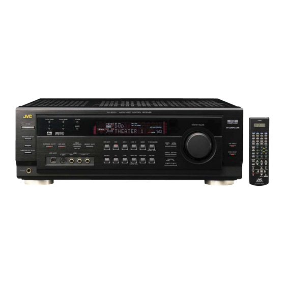
AUDIO/VIDEO CONTROL RECEIVER
RX-8010PBK / RX-8010VBK
RX-8012PSL
CATV/DBS
VCR 1
TV
AUDIO
DVD
DVD MUILTI
CD
FM/AM
TV/DBS
VIDEO
CDR
PHONO
VCR 1
VCR 2
TAPE/MD
USB
SURROUND
DSP
ANALOG/DIGITAL SLEEP
ON/OFF
MODE
INPUT
BASS
ROOM
LINE DIF .ECT
BOOST
EFFECT
SIZE
1
2
3
MIDNIGHT
MENU
TEST
CTR TONE
LIVENESS
MODE
4
5
6
ENTER
∗
∗
∗
STANDBY
SUBWFR
L/R BAL
CENTER
SOUND
7/P
8
9
∗
∗
∗
DIGITAL EQ
REAR L
REAR R
STANDBY/ON
MUTING
0
10
+10
RETURN
FM MODE
100 +
SPEAKERS ON/OFF
CATV/DBS
∗
CONTROL
CONTROL
BAL L
1
+
+
+
∗
CH/
LEVEL TV VOL
VOLUME
TV/VIDEO
−
−
−
2
∗
BAL R
PLAY
SUBWOOFER OUT ON/OFF
MENU
EXIT
TEXT
/REW
PAUSE
FF/
DISPLAY
SET
REC
DOWN – TUNING – UP
PAUSE
STOP
CONTROL
PHONES
A/V CONTROL RECEIVER
AUDIO/VIDEO CONTROL RECEIVER
FM/AM TUNING
FM/AM PRESET
FM MODE
MEMORY
D I G I T A L
D I G I T A L
S U R R O U N D
DVD MULTI
DVD
VCR 1
INPUT
SURROUND ON/OFF
DSP MODE
ANALOG/DIGITAL
MIDNIGHT MODE
INPUT ATT
USB AUDIO
VIDEO
S-VIDEO
VIDEO
L—AUDIO—R
PHONO
CD
CDR
PUSH OPEN
INSTRUCTIONS
MASTER VOLUME
VCR 2
VIDEO
TV SOUND/DBS
DIGITAL
LEVEL
EQ
ADJUST
SOUCE NAME
EFFECT SETTING
TAPE / MD
USB AUDIO
FM / AM
CONTROL
DOWN
UP
SOUCE NAME
LINE DIRECT
BASS BOOST
D I G I T A L
For Customer Use:
Enter below the Model No. and Serial
No. which are located either on the rear,
bottom or side of the cabinet. Retain this
information for future reference.
Model No.
Serial No.
LVT0618-003A
[US, UN, UJ]
Advertisement
Table of Contents

Related Manuals for JVC RX-8010PBK


Summary of Contents for JVC RX-8010PBK
- Page 1 AUDIO/VIDEO CONTROL RECEIVER RX-8010PBK / RX-8010VBK RX-8012PSL CATV/DBS VCR 1 AUDIO DVD MUILTI FM/AM TV/DBS VIDEO PHONO VCR 1 VCR 2 TAPE/MD SURROUND ANALOG/DIGITAL SLEEP ON/OFF MODE INPUT AUDIO/VIDEO CONTROL RECEIVER BASS ROOM LINE DIF .ECT BOOST EFFECT SIZE MIDNIGHT...
- Page 2 Warnings, Cautions and Others / Caution –– switch! Disconnect the mains plug to shut the power off completely. The switch in any position does not disconnect the mains line. The power can be remote controlled. CAUTION To reduce the risk of electrical shocks, fire, etc.: 1.
- Page 3 No obstructions in 15 cm from the back Bottom: No obstructions, place on the level surface. In addition, maintain the best possible air circulation as illustrated. Spacing 15 cm or more RX-8010PBK/RX-8010VBK RX-8012PSL Wall or obstructions Front Stand height 15 cm or more...
-
Page 4: Table Of Contents
AV COM PU LIN K Remot e Cont r ol Syst em ..4 7 Showing the Text Information on the Display ......21 Oper at ing JVC’s Audio/ Video Component s ... 4 9 Basic Setting and Adjustment — Auto Memory ...... 21 Operating Audio Components .......... -
Page 5: Par T S Ident Ificat Ion
Par t s Ident ificat ion Become familiar with the buttons and contr ols on the r eceiver befor e use. Refer to the pages in par entheses for details. pq w e r t 3 4 5 AUDIO/VIDEO CONTROL RECEIVER FM/AM TUNING FM/AM PRESET FM MODE... -
Page 6: Get T Ing St Ar T Ed
Get t ing St ar t ed This section explains how to connect audio/ video components and speaker s to the receiver, and how to connect the power supply. Befor e Inst allat ion Connect ing t he FM and AM Ant ennas Gener al FM Ant enna Connect ions •... -
Page 7: Connecting The Speakers
AM Ant enna Connect ions Basic connect ing pr ocedur e Snap the tabs on the loop into the ANTENNA slots of the base to assemble the FM 75 AM loop. COAXIAL AM Loop Antenna 1 Cut, twist and remove the insulation at the end of LOOP each speaker signal cable (not supplied). -
Page 8: Connecting Audio/Video Components
About t he speaker impedance Connect ing Audio/ Video Component s The required speaker impedance of the front speakers does differ depending on whether both the FRONT SPEAKERS 1 and FRONT You can connect the following audio/video components to this SPEAKERS 2 terminals are used or only one of them is used. - Page 9 Video component connect ions CD player AUDIO RIGHT LEFT Use the cables with RCA pin plugs (not supplied). Connect the white plug to the audio left jack, the red plug to the REAR audio right jack, and the yellow plug to the video jack. •...
- Page 10 TV SOUND Note: • When you connect the DVD player with its analog discrete output For RX-8010PBK and RX-8012PSL — Use a TV of a PAL or multi- color system. (5.1 CH reproduction) jacks: For RX-8010VBK — Use a TV of an NTSC or multi-color system.
-
Page 11: Digital Connections
Notes: Digit al Connect ions • When shipped from the factory, the DIGITAL IN terminals have This receiver is equipped with four DIGITAL IN terminals — one been set for use with the following components. digital coaxial terminal and three digital optical terminals, and one –... -
Page 12: Usb Connection
5. Check if the drivers are correctly installed. USB Connect ion 1. Open the Control Panel on your PC: Select [Start] = This receiver is equipped with a USB terminal on the front panel. [Settings] = [Control Panel] You can connect your PC to this terminal and enjoy sound 2. -
Page 13: Connecting The Power Cord
Put t ing Bat t er ies in t he Remot e Cont r ol Connect ing t he Power Cor d Before using the remote control, put two supplied batteries first. Before plugging the receiver into an AC outlet, make sure that all connections have been made. -
Page 14: Basic Oper At Ions
Basic Oper at ions The following oper ations ar e commonly used when you play any sound sour ce. Befor e using t he r emot e cont r ol Fr om t he r emot e cont r ol: To turn on the power, press AUDIO How to confirm the remote control operation mode AUDIO... -
Page 15: Adjusting The Volume
Notes: On t he fr ont panel: • When connecting an MD recorder (to the TAPE/MD jacks), and a DVD MULTI VCR 1 VCR 2 VIDEO TV SOUND/DBS DBS tuner (to the TV SOUND/DBS jacks), change the source names shown on the display. For details, see page 16. SOURCE NAME •... -
Page 16: Selecting The Front Speakers
Select ing t he Fr ont Speaker s M ut ing t he Sound On t he fr ont panel ON LY: Fr om t he r emot e cont r ol ON LY: When you have connected two pairs of the front speakers, you can Press MUTING to mute the sound through all MUTING select which to use. -
Page 17: Activating The Subwoofer Sound
At t enuat ing t he Input Signal Act ivat ing t he Subwoofer Sound When the input level of the playing source is too high, the sounds You can cancel the subwoofer sound even though you have connected a subwoofer and have set “SUBWOOFER” to “YES” will be distorted. -
Page 18: Adjusting The Equalization Patterns
Adjust ing t he Equalizat ion Pat t er ns Using t he Sleep Timer You can adjust equalization to your preference. Using the Sleep Timer, you can fall asleep to music and know the • You can do this setting for each source. receiver will turn off by itself rather than play all night. -
Page 19: Basic Set T Ings
Basic Set t ings Some of the following settings ar e r equir ed after connecting and positioning your speaker s in your listening r oom, while other s will make oper ations easier. When changing the source name from “TV” to Adjust ing t he Fr ont Speaker Out put “DBS”: Balance... -
Page 20: Setting The Subwoofer Information
Set t ing t he Subwoofer Infor mat ion Set t ing t he Speaker s for a Sur r ound Field Register whether you have connected a subwoofer or not. To obtain the best possible surround sound of the Surround and DSP Before you start, remember.. - Page 21 Cent er Delay Time Set t ing Center speaker Right front Register the delay time of the sound from the center speaker, Left front speaker speaker comparing to that of the sound from the front speakers. If the distance from your listening point to the center speaker is equal to that to the front speakers, select 0 ms.
-
Page 22: Digital Input (Digital In) Terminal Setting
Low Fr equency Effect At t enuat or Set t ing To set t he DIGITAL 2 / 3 / 4 t er minals: If the bass sound is distorted while playing back a source using 1. Press SETTING again until T SETTING Dolby Digital or DTS Digital Surround, follow the procedure below. -
Page 23: Selecting The Analog Or Digital Input Mode
When playing a software encoded with the Dolby Digital or Select ing t he Analog or Digit al Input DTS Digital Surround, “DGTL AUTO” may not work properly M ode and the following symptoms may occur: • Sound does not come out at the beginning of playback. When you have connected digital source components using the •... -
Page 24: Showing The Text Information On The Display
Showing t he Text Infor mat ion on t he Basic Set t ing and Adjust ment — Aut o M emor y Display Without any setting required, this receiver stores different sound When you have connected an MD recorder or CD player equipped settings for each different playing source automatically whenever with TEXT COMPU LINK remote control system (see page 42), you do the following:... -
Page 25: Receiving Radio Br Oadcast
Receiving Radio Br oadcast s You can browse thr ough all the stations or use the pr eset function to go immediately to a par ticular station. Notes: Set t ing t he AM Tuner Int er val Spacing • When a station of sufficient signal strength is tuned in, the TUNED indicator lights up on the display. -
Page 26: Selecting The Fm Reception Mode
To t une in a pr eset st at ion Select ing t he FM Recept ion M ode On t he fr ont panel: W hen an FM st er eo br oadcast is har d t o 1. Press FM/AM to select the band FM/AM r eceive or noisy (FM or AM). -
Page 27: Cr Eat Ing A Sur R Ound Field In Your Room
Cr eat ing a Sur r ound Field in Your Room The built-in Sur r ound Pr ocessor pr ovides Sur r ound mode and four types of the DSP (Digital Signal Pr ocessor ) mode — DAP (Digital Acoustic Pr ocessor ) mode, 5 CH/ 4 CH Ster eo mode, 3 D-PHONIC mode, and HEADPHONE DSP mode. W ith this r eceiver, you can use a Sur r ound mode and a DSP mode at the same time. -
Page 28: Reproducing The Sound Field
The 3D-PHONIC mode is the result Direct sounds reach the listener directly without any reflection. On of research on sound localization technology carried out at JVC for the other hand, indirect sounds are delayed by the distances of the many years. -
Page 29: Available Dsp Modes According To The Speaker Arrangement
Available DSP M odes Accor ding t o t he Speaker Ar r angement Available DSP modes will vary depending on how many speakers are used with this receiver. Make sure that you have set the speaker information correctly (see page 17). Speaker arrangements Available DSP modes Each time you press DSP MODE, the DSP modes change as follows:... -
Page 30: Adjusting The Surround Modes
5. Select the speaker you want to adjust. Adjust ing t he Sur r ound M odes • To select the center speaker level, press CENTER. “CTR” appears on the remote control display window. You can also use a Surround mode with a DAP mode (see page 30). •... -
Page 31: Adjusting The Dap Modes
SURROUND ON/OFF On t he fr ont panel: 2. Press SURROUND ON/OFF to activate an appropriate Surround DSP MODE 1. Press DSP MODE repeatedly until mode — PRO LOGIC, DOLBY the DAP mode you want to adjust DIGITAL or DTS SURROUND. —... - Page 32 4. Adjust the overall levels of the effect. 3. Select the speaker you want to adjust. EFFECT SETT 1) Press EFFECT repeatedly until • To select the center speaker level, press CENTER. “EFFECT” appears on the display. “CTR” appears on the remote control display window. The display shows the current setting.
-
Page 33: Adjusting The Surround Modes With The Dap Modes
TEST 9. Press LIVENESS to adjust the liveness. LIVENESS 5. Press TEST to check the speaker • Each time you press the button, the output balance. MENU liveness changes as follows: “TEST TONE L” starts flashing on the display, and a test tone comes out of the LIVENESS 1 LIVENESS 2 LIVENESS 3... - Page 34 11.Press EFFECT to adjust the 3. Press DSP MODE repeatedly until DSP MODE EFFECT overall level of the effect. the DAP mode you want to adjust MENU • Each time you press the button, the effect — THEATER 1, THEATER 2, level changes as follows: HALL 1, HALL 2, LIVE CLUB, EFFECT 1...
-
Page 35: Adjusting The 5 Ch/4 Ch Stereo Mode
7. Adjust the room size (sense of spaciousness). 2. Adjust the speaker output levels. 1) Press EFFECT repeatedly until 1) Press LEVEL ADJUST repeatedly EFFECT SETTIN LEVEL ADJUST “ROOMSIZE” appears on the display. until one of the following indications The display shows the current setting. appears on the display. -
Page 36: Adjusting The 3D-Phonic Modes
∗ BAL L 4. Press LEVEL +/– to adjust the 3. Adjust the center tone. EFFECT SETT speaker output levels (–10 dB to 1) Press EFFECT repeatedly until “CTR ∗ LEVEL TONE” appears on the display. − +10 dB). The display shows the current setting. ∗... - Page 37 6. Press CTR TONE to select the CTR TONE ––––––––––––––– MEMO ––––––––––––––– center tone level you want. ENTER • Each time you press the button, the display Use this column to write down your DSP mode adjustments for changes to show the following: your future reference.
-
Page 38: Using T He Dvd M Ulti Playback M Ode
Using t he DVD M ULTI Playback M ode This r eceiver pr ovides the DVD M ULTI playback mode for repr oducing the analog discr ete output mode of the DVD player. Befor e playing back a DVD, r efer also to the manual supplied with the DVD player. Fr om t he r emot e cont r ol: Act ivat ing t he DVD M ULTI Playback M ode 1. -
Page 39: Using T He On-Scr Een M Enus
MENU. • The on-screen display is shown in black and white. 2. Press 5 / ∞ to move • For RX-8010PBK and RX-8012PSL — Use a TV of a PAL or to “INPUT.” multi-color system. For RX-8010VBK — Use a TV of an NTSC or multi-color 3. -
Page 40: Adjusting The Equalization Pattern
For Surround mode, Surround mode with DAP Adjust ing t he Equalizat ion Pat t er n mode: (Also see page 15) “TEST TONE”: Output a test tone. 1. Press MENU. “L/R BALANCE”: Adjust the right and left balance The MENU appears on the TV. of the front speakers. -
Page 41: Adjusting The Dvd Multi Playback Mode
7. Press 5 / ∞ to move 5. Press 5 / ∞ to move to the item you want to to “EFFECT ADJUST,” set or adjust, then press 2 / 3. then press 2 / 3. On this adjustment menu, you can do the following: “L/R BALANCE”: Adjust the right and left balance The EFFECT ADJUST menu... -
Page 42: Selecting The Line Direct Function
Oper at ing t he Tuner (Also see pages 22 and 23) Select ing t he Line Dir ect Funct ion (Also see page 14) 1. Select FM or AM as the playing source. 1. Press MENU. Press FM/AM. The MENU appears on the TV. 2. -
Page 43: Setting The Basic Setting Items
SETTING 2 menu Set t ing t he Basic Set t ing It ems “DIGITAL 1/2/3/4”: Set the digital input terminal 1/2/3/4 (Also see pages 16 – 21) (see page 19). 1. Press MENU. “VIDEO DVD”: Set the video input terminal for the The MENU appears on the TV. -
Page 44: Com Pu Lin K Remot E Cont R Ol Syst
COM PU LIN K Remot e Cont r ol Syst em The COM PU LINK r emote contr ol system allows you to oper ate JVC audio components thr ough the r emote sensor on the r eceiver. To use this remote control system, you need to connect JVC audio... -
Page 45: Text Com Pu Lin K Remot E Cont R Ol Syst
TEXT COM PU LIN K Remot e Cont r ol Syst em The TEXT COM PU LINK r emote contr ol system has been developed to deal with the disc infor mation r ecor ded in the CD Text* and M Ds. Using these infor mation in the discs, you can oper ate the CD player or M D r ecor der equipped with the TEXT COM PU LINK remote contr ol system through the r eceiver. -
Page 46: Showing The Disc Information On The Tv Screen
1 Source name: CD or MD OPERATION S: 2 Select , then press SET to change the disc. 3 Track numbers and track titles. To use this remote control system, you need to connect the TV to the • When you move to a track number, you can MONITOR OUT jack on the rear panel (see page 7), and set the change the track information by pressing 2 / 3. -
Page 47: Searching For A Disc (Only For The Cd Player)
Sear ch for a disc by it s disc t it le: Sear ching for a Disc (Only for t he CD player ) 1. Press TEXT DISPLAY while “CD” is selected as Sear ch for a disc by it s per for mer : the source. -
Page 48: Entering The Disc Information
Sear ch for a disc by it s genr e: Ent er ing t he Disc Infor mat ion 1. Press TEXT DISPLAY while “CD” is selected as For t he CD Player wit h t he disc memor y funct ion: the source. - Page 49 For t he M D r ecor der : 4. Repeat step 3 until you finish putting a You can write the disc information (disc title and song titles) into the disc. You can only write the song title for the song currently performer name (up to selected.
-
Page 50: Av Com Pu Lin K Remot E Cont R Ol Syst
AV COM PU LIN K Remot e Cont r ol Syst em The AV COM PU LINK remote contr ol system allows you to oper ate JVC video components (TV, VCR, and DVD player ) thr ough the r eceiver. - Page 51 One-Touch DVD Play 1. If you have already plugged your VCR 1 (VCR connected to the VCR 1 jacks), DVD player, TV Simply by starting playback on the DVD player, you can enjoy the DVD playback without setting other switches manually. and this receiver into the AC outlets, unplug their •...
-
Page 52: Oper At Ing Jvc's Audio/ Video Component
Oper at ing JVC’s Audio/ Video Component s You can oper ate JVC’s audio and video components with this r eceiver ’s r emote control, since contr ol signals for JVC components ar e pr eset in the r emote contr ol. - Page 53 CD changer CD r ecor der After selecting “CDDSC” by pressing CONTROL repeatedly, you After pressing CDR (or selecting “CDR” by pressing CONTROL can perform the following operations on a CD changer: repeatedly), you can perform the following operations on a CD recorder: 3 PLAY: Starts playing.
-
Page 54: Operating Video Components
VCR 1: using cables with RCA pin plugs (see pages 6 and 7). 1 – 9, 0: • Some JVC VCRs can accept two types of the control signals — Selects the TV channels on the VCR. 3 PLAY: remote code “A”... -
Page 55: Operating Other M Anufacturers' Video Equipment
Operating Other M anufacturers’ Video Equipment This remote control supplied with the receiver can transmit control To change t he t r ansmit t able signals for signals for other manufacturers’ VCRs, TVs, CATV converters, oper at ing anot her manufact ur er ’s TV DBS tuners and DVD players. - Page 56 To change t he t r ansmit t able signals for For CATV converter oper at ing a CATV conver t er or DBS t uner Manufacturer Codes GENERAL INSTRUMENT 06, 07, 08, 09, 10, 11, 12, 13, 14, 29 1.
- Page 57 Manufacturer Codes After pressing DVD, these buttons ROOM 00, 26, 27, 28, 29, 58 EFFECT SIZE can be used for the DVD menu AIWA 01, 02 operations. MENU BELL & HOWELL TEST CTR TONE LIVENESS BLAUPUNKT 04, 05 Note: 06, 07 ENTER For detailed menu operations, refer to ∗L/R BAL...
-
Page 58: Tr Oubleshoot Ing
Tr oubleshoot ing Use this char t to help you solve daily oper ational problems. If ther e is any pr oblem you cannot solve, contact your JVC ser vice center. PROBLEM POSSIBLE CAUSE SOLUTION The display does not light up. - Page 59 PROBLEM POSSIBLE CAUSE SOLUTION “OVERLOAD” starts flashing on the Speakers are overloaded because of high 1. Press STANDBY/ON on the front display. volume. panel to turn off the receiver. 2. Stop the playback source. 3. Turn on the receiver again, and adjust the volume.
-
Page 60: Specificat Ions
1 V(p-p)/75 Ω S-video: VCR 1, VCR 2, MONITOR OUT: (Y: luminance): 0.286 V(p-p)/75 Ω (C: chrominance, burst): 1 V(p-p)/75 Ω Component video: MONITOR OUT: (Y: luminance): 0.7 V(p-p)/75 Ω Synchronization: Negative Signal-to-Noise Ratio: 45 dB On-Screen Color System: RX-8010PBK/RX-8012PSL RX-8010VBK NTSC... - Page 61 FM t uner (IHF) Tuning Range: 87.50 MHz to 108.00 MHz 12.8 dBf (1.2 µV/75 Ω) Usable Sensitivity: Monaural: 21.3 dBf (3.2 µV/75 Ω) 50 dB Quieting Sensitivity: Monaural: 41.3 dBf (31.5 µV/75 Ω) Stereo: Signal-to-Noise Ratio (IHF-A weighted): Monaural: 78 dB at 85 dBf Stereo: 73 dB at 85 dBf...
- Page 62 Mains (AC) Line Instruction (not applicable for Europe, U. S. A. , Canada, Australia and U. K. ) 110V 220V 127V 230 - 240V VOLTAGE SELECTOR 110V 220V 127V 230 - 240V VOLTAGE SELECTOR CAUTION for mains (AC) line BEFORE PLUGGING IN, do check that your mains (AC) line voltage corresponds with the position of the voltage selector switch provided on the outside of this equipment and, if different, reset the voltage selector switch, to prevent...
- Page 63 This file has been downloaded from: www.UsersManualGuide.com User Manual and User Guide for many equipments like mobile phones, photo cameras, monther board, monitors, software, tv, dvd, and othes.. Manual users, user manuals, user guide manual, owners manual, instruction manual, manual owner, manual owner's, manual guide, manual operation, operating manual, user's manual, operating instructions, manual operators, manual operator, manual product, documentation manual, user maintenance, brochure, user reference, pdf manual Downloaded from:...
Need help?
Do you have a question about the RX-8010PBK and is the answer not in the manual?
Questions and answers