JVC RX-8030VBK Instructions Manual
Audio/video control receiver
Hide thumbs
Also See for RX-8030VBK:
- Instructions for use manual (109 pages) ,
- Service manual (16 pages) ,
- Instructions manual (114 pages)
Table of Contents
Advertisement
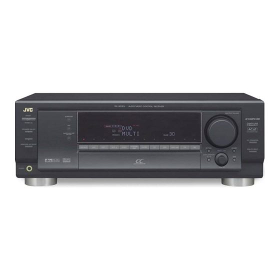
AUDIO/VIDEO CONTROL RECEIVER
RX-8030VBK
RX-8030V
SURROUND
STANDBY
STANDBY/ON
DSP
SPEAKERS ON/OFF
SURROUND/ DSP
1
OFF
2
DVD MULTI
DVD
VCR 1
VCR 2
SUBWOOFER OUT ON/OFF
PHONES
AUDIO/VIDEO CONTROL RECEIVER
MASTER VOLUME
TV SOUND
VIDEO
PHONO
CD
CDR
TAPE/MD
FM
AM
/DBS
SETTING
ADJUST
QUICK SPEAKER
SETUP
EXIT
PUSH OPEN
INSTRUCTIONS
A/V CONTROL RECEIVER
1
2
3
4
5
6
7/P
8
9
10/0
0
+10
CC CONVERTER
+
+
+
ANALOG DIRECT
−
−
−
For Customer Use:
Enter below the Model No. and Serial
No. which are located either on the rear,
bottom or side of the cabinet. Retain this
information for future reference.
Model No.
Serial No.
LVT1007-003A[UJ]
Advertisement
Table of Contents

Related Manuals for JVC RX-8030VBK


Summary of Contents for JVC RX-8030VBK
- Page 1 AUDIO/VIDEO CONTROL RECEIVER RX-8030VBK A/V CONTROL RECEIVER RX-8030V AUDIO/VIDEO CONTROL RECEIVER MASTER VOLUME SURROUND STANDBY STANDBY/ON SPEAKERS ON/OFF SURROUND/ DSP 10/0 CC CONVERTER TV SOUND DVD MULTI VCR 1 VCR 2 VIDEO PHONO TAPE/MD /DBS SUBWOOFER OUT ON/OFF ANALOG DIRECT...
- Page 2 • Do not expose this apparatus to rain, moisture, dripping or splashing and that no objects filled with liquids, such as vases, shall be placed on the apparatus. Spacing 15 cm or more RX-8030VBK Wall or obstructions Front Stand height...
-
Page 3: Table Of Contents
Using the Sleep Timer .............. 20 AV COMPU LINK Remote Control System ..40 Receiving Radio Broadcasts ......21 Operating JVC’s Audio/Video Components ... 42 Setting the AM Tuner Interval Spacing ........21 Operating Audio Components ..........42 Tuning in to Stations Manually ..........21 Operating Video Components .......... -
Page 4: Introduction
Introduction We would like to thank you for purchasing one of our JVC products. Before operating this unit, read this manual carefully and thoroughly to obtain the best possible performance from your unit, and retain this manual for future reference. -
Page 5: Parts Identification
Parts Identification 1 Display window • When the remote operation mode changes, it is shown on Remote Control this display. • Signal transmission indicator (A) lights up when transmitting signals. buttons (15, 44 – 46) A/V CONTROL RECEIVER CATV/DBS , VCR 1 , TV , AUDIO 3 Source selection buttons (15, 16, 17, 21, 22, 35, 38) -
Page 6: Front Panel
Front Panel TV SOUND VCR 1 VCR 2 VIDEO DVD MULTI PHONO TAPE/MD /DBS RX-8030V AUDIO/VIDEO CONTROL RECEIVER MASTER VOLUME SURROUND STANDBY STANDBY/ON SPEAKERS ON/OFF SURROUND/ DSP CC CONVERTER TV SOUND DVD MULTI VCR 1 VCR 2 VIDEO PHONO TAPE/MD /DBS SUBWOOFER OUT ON/OFF ANALOG DIRECT... - Page 7 Front Panel w • INPUT ANALOG button (18) STANDBY/ON button and STANDBY lamp (15) 2 • SPEAKERS ON/OFF 1 button (17) • INPUT ATT button (18) e MIDNIGHT MODE button (18) • SPEAKERS ON/OFF 2 button (17) 3 • SURROUND button (35) r INPUT DIGITAL button (18) t TUNER CONTROL buttons •...
-
Page 8: Rear Panel
Rear Panel VIDEO AUDIO DIGITAL IN PREOUT COMPU LINK-4 VIDEO S-VIDEO COMPONENT VIDEO SUBWOOFER CENTER RIGHT LEFT SURR BACK SURR CENTER FRONT (SYNCHRO) COMPULINK- ANTENNA FRONT 110V 220V TV SOUND SURR DIGITAL 1 (DVD) 127V (REAR) SUBWOOFER LOOP 230-240V MONITOR (REC) (REC) DIGITAL 2 (CD) -
Page 9: Getting Started
Getting Started This section explains how to connect audio/video components and speakers to the receiver, and how to connect the power supply. Before Installation Putting Batteries in the Remote Control General Precautions Before using the remote control, insert the two supplied batteries first. -
Page 10: Connecting The Speakers
Connecting the Speakers You can connect the following speakers: • Two pairs of front speakers to produce normal stereo sound. • One pair of surround speakers to enjoy the surround effect. • One surround back speaker or one pair of surround back speakers to enjoy to produce more effective surround effect. -
Page 11: Placing Speakers
Front speakers 1 Front speakers 2 Right Left Right Left Center speaker Surround back speakers* Right / Left CAUTION : SPEAKER IMPEDANCE CAUTION : SPEAKER IMPEDANCE SINGLE USE See Instruction Manual For Connection – – LEFT LEFT LEFT LEFT RIGHT RIGHT RIGHT RIGHT... -
Page 12: Connecting Audio/Video Components
Enhancing your audio system Connecting Audio/Video Components You can use this receiver as the pre-amplifier (control amplifier) When connecting individual components, refer also to the manuals when you connect power amplifiers to the PREOUT jacks on the supplied with them. rear using cables with RCA pin plugs (not supplied). - Page 13 Video component connections Cassette deck To listen to the sound after connection, press TAPE/MD. Use the cables with RCA pin plugs (not supplied). Connect the white plug to the audio left jack, the red plug to the You can connect either a cassette deck or an MD recorder to the audio right jack, and the yellow plug to the video jack.
- Page 14 VCR(s) TV and/or DBS tuner To listen to the sound after connection, press VCR 1 or VCR 2. To listen to the sound after connection, press TV SOUND/DBS (or TV/DBS on the remote control). You can connect two VCRs—one to the VCR 1 jacks and the other to the VCR 2 jacks.
- Page 15 DVD player • When you connect a DVD player with its analog discrete • When you connect a DVD player with stereo output jacks: output (5.1-channel reproduction) jacks: To listen to the sound after connection, press DVD. To listen to the sound after connection, press DVD MULTI. COMPONENT VIDEO COMPONENT VIDEO VIDEO...
-
Page 16: Digital Connections
Digital Connections Digital output terminal This receiver is equipped with four DIGITAL IN terminals—one You can connect any digital components which have an optical digital coaxial terminal and three digital optical terminals—and one digital input terminal. DIGITAL OUT (optical) terminal on the rear. Another digital optical input terminal is also located inside the front Digital optical cable (not supplied) door for conveniently connecting equipment such as a digital video... -
Page 17: Basic Operations
Basic Operations The following operations are commonly used when you play any sound sources. Operations hereafter will be explained using the buttons on the front panel. You can also use the buttons on the remote control for the same functions if they have the same and similar names/marks. Selecting the Source to Play Daily Operational Procedure RX-8030V... -
Page 18: Adjusting The Volume
Speaker and signal indicators on the display Selecting different sources for picture and sound By checking the following indicators, you can easily confirm which speakers you are activating and which signals are coming into this While watching pictures from a video source, you can listen to receiver. -
Page 19: Selecting The Front Speakers
Selecting the Front Speakers Remote Activating and Adjusting the Remote Subwoofer Sound When you have connected two pairs of the front speakers, you can select which to use. You can cancel the subwoofer sound even though you have connected a subwoofer and have set “SUB WOOFER” to “YES” RX-8030V AUDIO/VIDEO CONTROL RECEIVER (see page 25). -
Page 20: Setting The Dynamic Range
2. Press INPUT DIGITAL (or ANALOG/DIGITAL Setting the Dynamic Range INPUT on the remote control) to select “DGTL AUTO.” You can enjoy a powerful sound at night using the Midnight Mode. The DIGITAL AUTO indicator lights up on the display. RX-8030V AUDIO/VIDEO CONTROL RECEIVER DIGITAL AUTO... -
Page 21: Turning Analog Direct On And Off
1. Press TAPE/MD. Making Sounds Natural • Make sure “TAPE” appears on the display. JVC’s CC (Compensative Compression) Converter eliminates jitter 2. Press and hold TAPE/MD until “ASSGN MD” appears on and ripples, achieving a drastic reduction in digital distortion by the display. -
Page 22: Reinforcing The Bass
Using the Sleep Timer The following basic operations are possible only using the remote control. Using the Sleep Timer, you can fall asleep while listening to music. When the shut-off time comes, the receiver turns off automatically. BASS BOOST Reinforcing the Press SLEEP repeatedly. -
Page 23: Receiving Radio Broadcasts
Receiving Radio Broadcasts You can browse through all the stations or use the preset function to go immediately to a particular station. Setting the AM Tuner Interval Spacing From the remote control: Remote 1. Press FM/AM. • Each time you press the button, the band alternates between RX-8030V AUDIO/VIDEO CONTROL RECEIVER FM and AM. -
Page 24: Selecting The Fm Reception Mode
To tune in a preset station Selecting the FM Reception Mode On the front panel: RX-8030V AUDIO/VIDEO CONTROL RECEIVER RX-8030V AUDIO/VIDEO CONTROL RECEIVER When an FM stereo broadcast is hard to receive or noisy, you can change the FM reception mode while receiving an FM broadcast. 1. -
Page 25: Basic Settings
Basic Settings Some of the following settings are required after connecting and positioning your speakers while others will make operations easier. You can use QUICK SPEAKER SETUP to easily set up your speaker configuration. 3. Press in MULTI JOG (PUSH SET). Setting the Speakers Configuration Remote “ROOM SIZE?”... -
Page 26: Basic Setting Items
Speakers (channels) number and size Basic Setting Items You can find how each of the speaker size is defined according to the number of connected speakers (speaker channel (CH) number) On the following pages, you can adjust the following items: you select. -
Page 27: Basic Procedure
Basic Procedure : shows the initial setting in the following tables. RX-8030V AUDIO/VIDEO CONTROL RECEIVER Setting the Speakers To obtain the best possible surround effect from the Surround and DSP modes, register the setting about the speaker arrangement after all connections are completed. •... -
Page 28: Setting The Speaker Distance
Setting the Speaker Distance Setting the Bass Sounds The distance from your listening point to the speakers is another You can adjust subwoofer and bass sounds precisely according to important element to obtain the best possible sound of the Surround your preference. -
Page 29: Selecting Main Or Sub Channel-Dual Mono
7 Low frequency effect attenuator—LFE ATTENUATE Setting the Digital Input Terminals If the bass sound is distorted while playing back software When you use the digital input terminals, register which components encoded with Dolby Digital or DTS, set the LFE level to you have connected to the digital input terminals. -
Page 30: Setting The Component Video Input
Setting the Component Video Input Memorizing the Volume Level for Each Source When you use the component video inputs for connecting the DVD This unit memorizes some settings separately for each source. player and/or DBS tuner, register the type of input jacks. In addition, you can store the volume level for each source with the If you have not selected appropriate video input jacks, the AV other memorized settings—One Touch Operation. -
Page 31: Adjusting Sound
Adjusting Sound You can make sound adjustment to your preference after completing basic setting. Basic Setting Items Basic Procedure On the following pages, you can adjust the items listed below: RX-8030V AUDIO/VIDEO CONTROL RECEIVER • You can adjust only the items applicable to the current sound mode. -
Page 32: Adjusting The Equalization Patterns
Adjusting the Equalization Patterns Adjusting the Speaker Output Levels You can adjust the equalization patterns to your preference. You can adjust the speaker output levels. The test tone comes out of • Once you have made adjustment, it is memorized for each source. each speaker except subwoofer to check the output level balance when using the Surround mode. -
Page 33: Adjusting The Sound Parameters For The Surround And Dsp Modes
Adjusting the Sound Parameters for the You can also use the remote control for adjusting the speaker Surround and DSP Modes output level. You can adjust the Surround and DSP sound parameters to your When using the remote control, you can make an adjustment preference. -
Page 34: Using The Surround Modes
Using the Surround Modes This unit activates a variety of Surround modes automatically. The basic settings and adjustments stored (see pages 23 to 31) are applied. Reproducing Theater Ambience Introducing the Surround Modes In a movie theater, many speakers are located on the walls to Dolby Digital* reproduce impressive multi-surround sounds, reaching you from all Dolby Digital is a digital signal compression method, developed... - Page 35 DTS-ES Discrete 6.1ch has been designed to encode (and decode) • If the surround speakers and center speaker are set to a 6.1-channel signal discretely to avoid interference with each “NONE” in the speaker setting, JVC’s original 3D-PHONIC channel. processing (which has been developed to create the surround DTS-ES Matrix 6.1ch has been designed to add an extra surround...
-
Page 36: Surround Modes Applicable To The Various Software
Surround Modes Applicable to the Various Software Available Surround modes vary depending on the speaker settings and the incoming signals. The table below shows the relation of the Surround modes and the incoming signals (with the surround back speakers and EX/ES setting). •... -
Page 37: Activating The Surround Modes
Activating the Surround Modes Activating the Surround Modes RX-8030V AUDIO/VIDEO CONTROL RECEIVER Available Surround modes vary depending on the speaker settings and the incoming signals. (See page 34.) Activating one of the Surround modes for a source automatically recalls the memorized settings and adjustments (see pages 23 to 31.) You can also use the buttons on the remote control for the same 1. -
Page 38: Using The Dsp Modes
• If surround speakers are set to “NONE” in the speaker setting, “3D H PHONE” appears on the display and the DSP and JVC’s original 3D-PHONIC processing (which has been HEADPHONE indicators also light up. developed to create the surround effect through the front speakers only) is used. -
Page 39: Activating The Dsp Modes
All Channel Stereo mode Activating the DSP Modes This mode can reproduce a larger stereo sound field using all the connected (and activated) speakers. This mode cannot be used Activating one of the DSP modes for a source automatically without activating the surround speakers. recalls the memorized settings and adjustments (see pages 23 to •... -
Page 40: Using The Dvd Multi Playback Mode
Using the DVD MULTI Playback Mode This receiver provides the DVD MULTI playback mode for reproducing the analog discrete output mode of the DVD player. Activating the DVD MULTI Playback Mode Connection diagram RX-8030V AUDIO/VIDEO CONTROL RECEIVER COMPONENT VIDEO 1. Press DVD MULTI so that “DVD MULTI” appears on the display. -
Page 41: Compu Link Remote Control System
COMPU LINK Remote Control System The COMPU LINK remote control system allows you to operate JVC’s audio components through the remote sensor on the receiver. Automatic Source Selection To use this remote control system, you need to connect JVC’s audio... -
Page 42: Av Compu Link Remote Control System
This receiver is equipped with the AV COMPU LINK-III, which adds a function to the previous version in order to operate JVC’s video components through the video components terminals. To use this remote control system, connect the video components you want to operate, following the diagrams below and the procedure on the next page. - Page 43 1. If you have already plugged your VCR , DVD One-Touch DVD Play player, TV and this receiver into the AC outlets, Simply by starting playback on the DVD player, you can enjoy the unplug their AC power cords first. DVD playback without setting other switches manually.
-
Page 44: Operating Jvc's Audio/Video Components
Operating JVC’s Audio/Video Components You can operate JVC’s audio and video components with this receiver’s remote control, since control signals for JVC’s components are preset in the remote control. Tuner Operating Audio Components You can always perform the following operations:... - Page 45 CD changer CD recorder After selecting “CDDSC” by pressing CONTROL repeatedly, you After pressing CDR (or selecting “CDR” by pressing CONTROL can perform the following operations on a CD changer: repeatedly), you can perform the following operations on a CD recorder: Start playing.
-
Page 46: Operating Video Components
Stop playing or recording. Pause playing. To resume, press 3. • When another JVC’s VCR is connected to the VCR 2 or VIDEO terminals, set its remote control code to code “B.” (This remote REC PAUSE: Enter recording pause by pressing this button. -
Page 47: Operating Other Manufacturers' Video Equipment
Operating Other Manufacturers’ Video Equipment This remote control supplied with the receiver can transmit control signals for other manufacturers’ TVs, CATV converters, DBS tuners, VCRs and DVD players. To change the transmittable signals for When operating the other manufacturers’ components, refer also to the manuals supplied with them. - Page 48 To change the transmittable signals for To change the transmittable signals for operating another manufacturer’s VCR operating another manufacturer’s DVD player 1. Press and hold VCR 1 1. Press and hold AUDIO 2. Press VCR 1. 2 Press DVD. “CALL” appears on the display window of the remote control. “CALL”...
- Page 49 For TV For VCR Manufacturer Codes Manufacturer Codes Manufacturer Codes , 02, 13, Quelle 52, 53, 54, 55, , 26, 27, 28, 29, 58 14, 47, 74 56, 57, 58, 59, Aiwa 01, 02 Akai 01, 02 60, 61, 62, 63, Bell &...
-
Page 50: Troubleshooting
Troubleshooting Use this chart to help you solve daily operational problems. If there is any problem you cannot solve, contact your JVC’s service center. PROBLEM POSSIBLE CAUSE SOLUTION The display does not light up. The power cord is not plugged in. -
Page 51: Specifications
Specifications Amplifier Video Video Input Sensitivity/Impedance Output Power Composite video: At Stereo operation DVD IN, VCR 1 IN, VCR 2 IN, TV SOUND/DBS IN, VIDEO: 100 W per channel, min. RMS, driven into 8 Ω at Front ch: 1 V(p-p)/75 Ω 1 kHz, with no more than 0.8% total harmonic S-video: distortion. - Page 52 Mains (AC) Line Instruction (not applicable for Europe, U.S.A., Canada, Australia and U.K.) 110V 220V 127V 230 - 240V VOLTAGE SELECTOR 110V 220V 127V 230 - 240V VOLTAGE SELECTOR CAUTION for mains (AC) line BEFORE PLUGGING IN, do check that your mains (AC) line voltage corresponds with the position of the voltage selector switch provided on the outside of this equipment and, if different, reset the voltage selector switch, to...
Need help?
Do you have a question about the RX-8030VBK and is the answer not in the manual?
Questions and answers