Table of Contents
Advertisement
Owner's Manual
I:RI:IFT. MRN ®
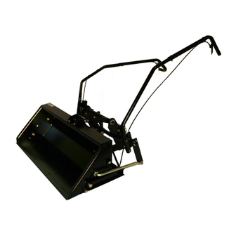
Model No. 486.24847
FRONT SCOOP TRACTOR ATTACHMENT
CAUTION:
Before
using
this product,
read this
manual
and follow
all Safety
Rules
and Operating
Instructions.
IMPORTANT
- READ THIS FIRST???
For Missing
Parts or Assembly
Questions
Please
Call 866-576-8388
Mon.-Fri.
7 a.m.-5
p.m. CST.
FAX 217-728-2032
or e-mail info@aqri-fab.com
Missing
parts will be sent UPS in 24 hours directly
to your home.
• Safety
• Assembly
• Operation
• Maintenance
• Parts
Sears, Roebuck
and Co., Hoffman
Estates,
IL 60179 U.S.A.
www.sears.com/craftsma
n
PRINTED IN U.S.A.
FORM
NO. 49326
(1/05)
Advertisement
Table of Contents

Related Manuals for Craftsman 486.24847


Summary of Contents for Craftsman 486.24847
- Page 1 Owner's Manual I:RI:IFT. MRN ® Model No. 486.24847 FRONT SCOOP TRACTOR ATTACHMENT CAUTION: Before using this product, read this manual and follow all Safety Rules and Operating Instructions. • Safety IMPORTANT - READ THIS FIRST??? • Assembly For Missing Parts or Assembly Questions Please Call 866-576-8388...
- Page 2 OPERATION ............PARTS ORDERING/SERVICE ....Back Page LIMITED ONE YEAR WARRANTY ON CRAFTSMAN FRONT SCOOP TRACTOR ATTACHMENT For one year from the date of purchase, when this scoop is maintained and lubricated according to the operating and maintenance instructions in this owner's manual, Sears will repair any defect in material or workmanship free of charge.
- Page 3 Anypower e quipment cancause injury ifoperated improperly oriftheuser d oesnotunderstand how tooperate theequipment. Exercise caution atalltimes, w henusing power equipment. • Read this owner'smanual before attemptingto • Neverramthe scoopintomaterial a t highspeed. assemble or operate the scoopattachment. • Vehiclebraking andstability maybeaffected withthe •...
- Page 5 PARTS NOT SHOWN FULL SIZE PARTS BAG CONTENTS Not all parts will be needed for fit-up to any one tractor. Discard uneeded parts after assembly is finished. DESCRIPTION REF. REF. QTY. QTY. DESCRIPTION Bolt, 5/8" x 1-1/2" Lock Washer, 3/8" Bolt, 1/2"...
-
Page 6: Table Of Contents
CARTON CONTENTS 15. Lift Handle Tube 1. Bucket Assembly 8. Right (GT) Side Plate 2. Pin Stop Bracket 9. Left (GT) Side Plate 16. Dump Handle Tube Extension 3. Lift Frame Assembly 10. Dump Control Rod 17. Dump Pivot Bracket 18. -
Page 7: Bucket Assembly
TOOLS REQUIRED FOR ASSEMBLY ______------ 5/16" x 1" HEX BOLT #2 Phillips Screwdriver Standard Screwdriver 15/16" Wrenches (one should be box-end) 5/16" WASHERS PIN STOP 3/4" Wrenches 9/16" Wrenches 7/16" Wrenches ./BRACKET 1/2" Wrenches BUCKET 3/8" Wrench ASSEMBLY ADDITIONAL ITEMS NEEDED Ruler or Tape Measure Grease 5/16"... -
Page 8: Lift Frame Assembly
STEP 5-INSTALL LIFT BRACKET ASSEMBLY STEP 7 - INSTALL LIFT STRAP ASSEMBLIES • Loosen the bolts and nuts on the lift strap • Assemble the lift bracket assembly to the lift frame assemblies 1/4 turn or until the straps will slide back assembly using two 5/8"... -
Page 9: Tilt Bracket Assembly
STEP 8 - INSTALL TILT BRACKET ASSEMBLY STEP 9 - INSTALL DUMP PIVOT BRACKET Install a 1/8" x 1-1/2" cotter pin to the inside hole in NOTE: If you mounted the lift strap assemblies in Step 7 the shaft shown in figure 9, and then install a 1" to the rear holes in the lift frame for increased washer onto the shaft. - Page 10 STEP 11 - INSTALL TILT STOP BRACKETS STEP 13 - INSTALL LIFT HANDLE TUBE EXTENSION Install a tilt stop bracket to each side of the bucket using a 1/4" x 3/4" carriage bolt, 1/4" washer and 1/4" • Install the lift handle tube extension on the lift handle nylock nut.
-
Page 11: Dump Handle Tube Extension
STEP 16 - INSTALL DUMP HANDLE TUBE LmFT TRIGGER EXTENSION • Install the dump handle tube extension on the dump LIFT CABLE handle tube using a 1/4" x 1-3/4" hex bolt and 1/4" nylock nut. See figure 14. DUMP HANDLE o OSTMENT- TUBE EXTENSION CABLE... -
Page 12: Dump Control Pin
STEP 18 - INSTALL DUMP CONTROL STEP 19 - INSTALL HOSE CLIP AND SPACER Install a small 1/2" washer and then the compression Secure the dump cable to the back of the bucket using spring onto the dump control pin. Install the dump a hose clip, #10 x 5/8"... - Page 13 Remove any bolts present in the mounting holes on the left side of the tractor frame. Do not remove bolts from right side of frame until left side plate has been installed. See figure 19. Install the left (LT) side plate on the tractor with the LEFT (GT) SIDE PLATE spacer to the outside.
- Page 14 STEP 23- ADJUST TILT BRACKETASSEMBLY STEP 24 - ADJUST LIFT STRAPS Lower the scoop assembly onto a smooth level Make sure the nuts and bolts in the lift straps are surface. For normal use, let the bottom of the bucket loose enough to turn by hand.
- Page 15 KNOW YOURFRONTENDSCOOP Always test to make sure your vehicle has adequate power and braking capabilities whenever Read this owner's manual and safety rules before hauling a substantial amount of weight in your front operating your front end scoop. end scoop. Use extra caution when operating Compare the illustration below with your front end scoop slopes.
- Page 16 CUSTOMER RESPONSIBILITIES • Read and follow the maintenance schedule and the maintenance procedures listed in this section. .._ _e/_e_/'_o_/'_, __o_" MAINTENANCE SCHEDULE Fill in dates as you ___J Service Dates complete regular service. ,_e__e_ Check for loose fasteners Cleaning Lubricate CHECK FORLOOSEFASTENERS LUBRICATION...
- Page 17 NOTES...
- Page 18 REPAIR PARTS FOR MODEL 486.24847 31 3! 28 [ !_ _ > rs / 631i...
- Page 19 REPAIR PARTS FOR MODEL 486.24847 PART REF. PART DESCRIPTION QTY. DESCRIPTION 1509-69 43093 Cotter Pin, 1/8" x 1-1/2" Hex Bolt, 1/4-20 x 1-3/4" (Grade 5) Cable Tie 726-0178 710-0865 Hex Bolt, 1/2-13 x 1" (Grade 5) Lift Tube Handle Extension 49265 R19212016 Flat Washer, 5/8"...
- Page 20 NOTES...
- Page 21 NOTES...
- Page 22 NOTES...
- Page 23 SIGHT AND HOLD THIS LEVEL WITH A VERTICAL TREE e- o _b..,2" €- ° c oo ¢o €_ ,_ 0 €- ;.E ° "_ o CAUTION: DO NOT OPERATE YOUR TRACTOR AND SCOOP ON A SLOPE & IN EXCESS OF 10 DEGREES. BE SURE OF YOUR TRACTOR'S TOWING AND BRAKING CAPABILITIES BEFORE OPERATING ON ASLOPE.
- Page 24 For repair of major brand appliances in your own home... no matter who made it, no matter who sold it! for repair, call for the location of your nearest Sears Parts & Repair Center. t -800-488-1222 Anytime, day or night www.sears.com For the replacement parts, accessories...
Need help?
Do you have a question about the 486.24847 and is the answer not in the manual?
Questions and answers